Advertisement
Quick Links
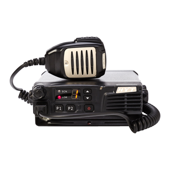
I. Key Functions
1-1 Front Panel
① Volume Knob
② Low Power Indicator
③ Scan Indicator
④ Channel Display Numeric LED
⑤ Channel Up Key
⑥ Channel Down Key
⑦ Rx/Tx Indicator
⑧ On/Off Key
⑨ P2 Key
⑩ P1 Key
⑪ Mic Jack
1-2 Panel Test Mode
■ When the function is off
Controls
Functions
Up
Channel Up
Down
Channel Down
PF1
Squelch On/Off
PF2
Channel scan
Selector Knob
Volume tuning
Adjustment Description
Description
Advertisement

Related Manuals for HYT TM-600


Summary of Contents for HYT TM-600
- Page 1 Adjustment Description I. Key Functions 1-1 Front Panel ① Volume Knob ② Low Power Indicator ③ Scan Indicator ④ Channel Display Numeric LED ⑤ Channel Up Key ⑥ Channel Down Key ⑦ Rx/Tx Indicator ⑧ On/Off Key ⑨ P2 Key ⑩...
- Page 2 1-3 Panel Tuning Mode Controls Function Description Tuning value up Down Tuning value down Test/Tuning mode toggle Save tuning value, then move to the next item. Selector Knob No function. II. Panel Test Mode Measure the transceiver’s Tx output, Rx sensitivity and other items. CTCSS, CDCSS, 2-Tone, MSK and DTMF signalling are decoded in this mode.
- Page 3 CTCSS frequency deviation (151.4Hz) CTCSS frequency deviation (254.1Hz) CDCSS frequency deviation DTMF frequency deviation MSK frequency deviation Single tone frequency deviation Rx sensitivity Squelch on level (Level 9) Squelch on level (Level 3) Squelch off level (Level 9) Squelch off level (Level 3) 3-2.
- Page 4 High CTCSS: 151.4Hz Medium Band Center CTCSS: 151.4Hz Narrow Band Center CTCSS: 151.4Hz Center CTCSS: 254.1Hz Wide Band CTCSS: 254.1Hz High CTCSS: 254.1Hz Medium Band Center CTCSS: 151.4Hz Narrow Band Center CTCSS: 254.1Hz Center CTCSS: 023N CDCSS Wide Band CTCSS: 023N Frequency High CTCSS: 023N...
-
Page 5: Flow Chart
High No signalling Level 3 Center Medium Band No signalling Level 3 Center Narrow Band No signalling Center No signalling Level 9 No signalling Wide Band High No signalling Level 9 Center Medium Band No signalling Level 9 Center Narrow Band No signalling Center No signalling... - Page 6 [PF6] [P1]+Power ON CDCSS deviation(Center) CDCSS deviation [P2] [PF6] Panel test mode CDCSS deviation(Low) [P2] [PF6] [P2] CDCSS deviation(High) 0. (Center) 0(High power) [PF6] [P2] CDCSS deviation(narrow 1. (Low) Center) [P2] [P2] [PF6] 2. (High) [UP] Rotate select knob [PF6] DTMF deviation DTMF deviation [PF6]...
- Page 7 IV. Test Instrument for Alignment Instrument Method Major Specifications Standard Signal Frequency 136 to 174 MHz Generator (SSG) Modulation Frequency modulation and external modulation Output power 0.1uV to 1mV above Power Meter Input Impedance 50Ω Operation Frequency 136 to 174 MHz or above Measurement Capability About 50W Digital Voltmeter (DVM)
- Page 8 V. Cautions When Removing or Attaching the Shield Cover 1. When handling with the shield cover, do not damage the components on the TX-RX unit. 2. When installing the shield cover, insert the cover from the rear side. 3. When removing the shield cover, squeeze the hole marked with an arrow as shown in the diagram and pull it straight up.
- Page 9 is no needed information in EEPROM when the radio is manufactured. ● Turn on the power while holding down [P2], and re-press it after the displays “0”. ● The LED on the control panel finishes flashing, indicating that the initialization is over. 3.
- Page 10 Measurement Adjustment Specification/R Item Condition emarks Test Instrument Terminal Part Method 1. Power supply Note: 1. This radio can only be installed in negative grounding 1. Power Supply voltage DC 13.6V electrical system. Reverse polarity will cause the cable fuse to blow. Check the vehicle ground polarity before the installation to avoid wasted time and effort.
- Page 11 Check deviation: Radio 7. Modulation 2.6KHz-3.4KHz (W) Communication Sensitivity 2.2KHz-2.7KHz (M) 1. Each CH Test Set 1.3KHz-1.7KHz (N) corresponds to a Filter: Check MIC Jack specific TX freq. 0.05-15KHz AF: 1KHz 8. Modulation 7.5mV ≤5% Distortion Radio Use “UP”, “DN” Each CH corresponds Communication Check...
- Page 12 Receiver Measurement Adjustment Specification Item Condition /Remarks Test Instrument Terminal Part Method Set the gain value to the First max; the manually Enter item “B”; Each CH corresponding 15. RF adjust corresponds to a specific Scanner ANT . TP1 freq is on the bandpass filter TC101, then TX freq.
- Page 13 level SSG Output: -112dBm (Level 9) Radio Communication Continuously No need to adjust Test Set Enter in turn the item “C” press[P2] software setting SSG Output: (Level 9 off), “D” (Level 3 key twice for 20. SQ Close at SQ Level 3/9; -123dBm (Level 3) off);...
Need help?
Do you have a question about the TM-600 and is the answer not in the manual?
Questions and answers