Table of Contents
Advertisement
Advertisement
Table of Contents

Related Manuals for Power Electronics SD300312


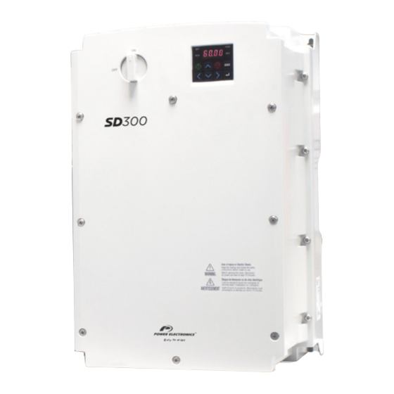
Summary of Contents for Power Electronics SD300312
- Page 1 VARIABLE SPEED DRIVE Variable Speed Drive Hardware and Installation Manual...
- Page 3 Variable Speed Drive Hardware and Installation Manual Edition: February 2017 SD30MTHW01CI Rev. C...
- Page 4 POWER ELECTRONICS SD300 SERIES SAFETY SYMBOLS...
-
Page 5: About This Manual
SD300 Programming and Software Manual. SD300 Hardware and Installation Manual. POWER ELECTRONICS CONTACT INFORMATION Power Electronics, S.A. C/ Leonardo da Vinci, 24 – 26 46980 – PATERNA SPAIN Tel. 902 40 20 70 (Spain) • Tel. (+34) 96 136 65 57 • Fax (+34) 96 131 82 01 Email: sales@power-electronics.com... - Page 6 POWER ELECTRONICS SD300 SERIES SAFETY SYMBOLS Always follow safety instructions to prevent accidents and potential hazards from occurring. In this manual, safety messages are classified as follows: Identifies potentially hazardous situations where dangerous voltage may be present, which if not avoided, could result in minor personal injury, serious...
- Page 7 Standard ratings, Power connection, Power terminals The equipment and technical documentation are periodically updated. Power Electronics reserves the right to modify all or part of the contents of this manual without previous notice. To consult the most updated information of this product, you may access through our website www.power-electronics.us...
-
Page 8: Table Of Contents
SD300 SERIES POWER ELECTRONICS TABLE OF CONTENTS About this manual ............................3 INTRODUCTION ..........................12 CONFIGURATION TABLE & STANDARD RATINGS..............13 TECHNICAL CHARACTERISTICS ....................16 DIMENSIONS ............................ 18 RECEPTION, HANDLING AND TRANSPORTATION..............26 MECHANICAL INSTALLATION ....................... 27 POWER CONNECTION ........................31... - Page 9 POWER ELECTRONICS SD300 SERIES CONTROL CONNECTION ........................ 41 COMMUNICATION ........................... 47 COMMISSIONING ..........................50 USE OF THE DISPLAY ........................52 MAINTENANCE ..........................56 ACCESSORIES ..........................58 DECLARATION OF CONFORMITY CE ..................... 61 TABLE OF CONTENTS...
- Page 10 In order to appropriately use the drive, please, follow all instructions described in the installation manual which refer to transportation, installation, electrical connection and commissioning of the equipment. Power Electronics accepts no responsibility or liability for partial or total damages resulting from incorrect use of equipment.
- Page 11 POWER ELECTRONICS SD300 SERIES CAUTION Install the drive on a non-flammable surface. Do not place flammable material nearby. Otherwise, a fire could occur. Disconnect the input power if the drive is damaged. Otherwise, it could result in a secondary accident or fire.
- Page 12 SAFETY Before operating the drive, read this manual thoroughly to gain an understanding of the unit. If any doubt exists, please contact POWER ELECTRONICS, (902 40 20 70 / +34 96 136 65 57) or your nearest agent. Wear safety glasses when operating the drive with power applied or for when the front cover is removed.
-
Page 13: For Instruccions On How To Use The Display, Refer To Chapter
POWER ELECTRONICS SD300 SERIES HOW TO USE THIS MANUAL Quick Guide Make sure model and serial number of the drive are the same on the delivery note and unit. Read carefully the safety instructions before installation, commissioning, operation and maintenance of the drive. See Safety Instructions section. -
Page 14: Introduction
SD300 SERIES POWER ELECTRONICS 1. INTRODUCTION The SD300 is a high performance general purpose AC drive suitable for demanding heavy duty applications that require high starting torque and precise control. The dual duty rating of the SD300 (IP20) also ensures compatibility with less demanding normal duty loads. -
Page 15: Configuration Table & Standard Ratings
POWER ELECTRONICS SD300 SERIES 2. CONFIGURATION TABLE & STANDARD RATINGS Configuration Table EXAMPLE CODE: SD305846F Drive current Degree of SERIE Drive Voltage EMC Filter (Normal Duty) protection SD3 SD300 230VAC single-phase IP20 Extended … 230VAC three-phase IP66 Standard 400VAC three-phase [1] Heavy duty for IP66 models. - Page 16 SD300 SERIES POWER ELECTRONICS Standard Ratings – 230VAC single-phase EMC STANDARD EMC EXTENDED Power ND Power HD Current ND Current HD (kW) (kW) Model Frame Model Frame 0.75 SD300312 SD300312F 0.75 SD300612 SD300612F SD300912 SD300912F 12.0 11.0 SD301212 SD301212F [1] EMC class 2.
- Page 17 POWER ELECTRONICS SD300 SERIES Standard ratings – 400VAC IP20 EMC STANDARD EMC EXTENDED Power ND (kW) Power HD (kW) Current ND (A) Current HD (A) Model Frame Model Frame 0.75 SD300242 SD300242F 0.75 SD300342 SD300342F SD300542 SD300542F SD300742 SD300742F SD301042...
-
Page 18: Technical Characteristics
No corrosive gas, flammable gas, oil mist and dust etc. indoors (Pollution Degree 3 Env.) Pressure 70~106 kPa Global certification CE, UL, cUL, RoHS REGULATIONS 3C2 Conformal coating [1] Please consult Power Electronics before the installation with this kind of motors. [2] Only available with IP20 protection degree. TECHNICAL CHARACTERISTICS... - Page 19 POWER ELECTRONICS SD300 SERIES Enhanced Sensorless Control Sensorless Control Starting torque of 200% / 0.5Hz is produced and provides robust power in the low speed region. The motor auto-tuning function is optimized to maximize motor performance. Figure 3.1 Sensorless control Flying Start Function The SD300 is capable of performing quick and reliable smooth restarts.
-
Page 20: Dimensions
SD300 SERIES POWER ELECTRONICS 4. DIMENSIONS IP20 Drives Dimensions Frame 1N Dimensions INPUT VOLTAGE PHASES EQUIPMENT 200~240[V] SD300322 380~480[V] SD300242 DIMENSIONS [mm/inch] WEIGHT (kg/lb) Ø 68 (2.7”) 61.1 (2.4”) 128 (5”) 119 (4.7”) 123 (4.8”) 4 (0.2”) 5 (0.2”) 3.5 (1.4”) 4.2 (1.65’’) - Page 21 POWER ELECTRONICS SD300 SERIES Frame 3N Dimensions INPUT VOLTAGE PHASES EQUIPMENT 200~240[V] SD300612 200~240[V] SD300922 380~480[V] SD300542 DIMENSIONS [mm/inch] WEIGHT (kg/lb) Ø 100 (3.9”) 91 (9.6”) 128 (5”) 120 (4.7”) 4.5 (0.2”) 4.5 (0.2”) 4.5 (0.2”) 4.5 (0.2”) 130 (5.1’’) 1.5 (3.3lb)
- Page 22 SD300 SERIES POWER ELECTRONICS Frame 5N Dimensions INPUT VOLTAGE PHASES EQUIPMENT 200~240[V] SD301212 200~240[V] SD301822 380~480[V] SD301042 DIMENSIONS [mm/inch] WEIGHT (kg/lb) Ø 140 (5.5”) 132.2 (5.2”) 128 (5”) 120.7 (4.8”) 3.7 (0.1”) 145 (5.7”) 3.9 (0.2”) 4.4 (0.2”) 4.5 (0.2”) 2.7 (6lb)
- Page 23 POWER ELECTRONICS SD300 SERIES Frame 2F Dimensions INPUT VOLTAGE PHASES EQUIPMENT 200~240[V] SD300612F, SD300912F 380~480[V] SD300542F, SD300742F DIMENSIONS [mm/inch] WEIGHT (kg/lb) Ø 100 (3.9”) 91 (3.6”) 180 (7.1”) 170 (6.7”) 5 (0.2”) 140 (5.5”) 4.5 (0.2”) 4.5 (0.2”) 4.2 (0.2”) 1.8 (4lb)
- Page 24 SD300 SERIES POWER ELECTRONICS Frame 4 Dimensions INPUT VOLTAGE PHASES EQUIPMENT 200~240[V] SD303022, SD304022 380~480[V] SD301642F, SD302342F DIMENSIONS [mm/inch] WEIGHT (kg/lb) Ø 160 (6.3”) 137 (5.4”) 232 (9.1”) 10.5 (0.4”) 140 (5.5”) 5 (0.2”) 5 (0.2”) 216.5 (8.5’’) 3.3 (7.3lb) Figure 4.9 Frame 4 dimensions...
- Page 25 POWER ELECTRONICS SD300 SERIES Frame 6 Dimensions INPUT VOLTAGE PHASES EQUIPMENT 200~240[V] SD306922 380~480[V] SD304442F, SD305842F DIMENSIONS [mm/inch] WEIGHT (kg/lb) Ø 220 (8.7”) 193.8 (7.6”) 331 (13”) 13 (0.5”) 187 (7.4”) 6 (0.2”) 6 (0.2”) 350 (13.8’’) 7.5 (15.4lb) Figure 4.11 Frame 6 dimensions...
- Page 26 SD300 SERIES POWER ELECTRONICS Frame 2I Dimensions INPUT VOLTAGE PHASES EQUIPMENT 200~240[V] SD300826, SD301126, SD301726 380~480[V] SD300446F, SD300646F, SD300946F DIMENSIONS [mm/inch] WEIGHT (kg/lb) Ø 220 (8.7”) 204 (8”) 259 (10”) 241 (9.5”) 12 (0.5”) 201 (7.9”) 215 (8.5”) 5.5 (0.2”) 5.5 (0.2”) 22.3 (0.9”) 28.6 (1.1”) 5.3 (12lb)
- Page 27 POWER ELECTRONICS SD300 SERIES Frame 4I Dimensions INPUT VOLTAGE PHASES EQUIPMENT 200~240[V] SD304626 380~480[V] SD302446F, SD303046F DIMENSIONS [mm/inch] WEIGHT (kg/lb) Ø 260 (10”) 229 (9”) 400 (16”) 377 (15”) 15 (0.6”) 246 (9.7”) 260 (10”) 6 (0.2”) 22.3 (0.9”) 34.9 (1.4”) 9.6 (21lb)
-
Page 28: Reception, Handling And Transportation
The SD300 is carefully tested and perfectly packed before delivery. In the event of transport damage, please ensure that you notify the transport agency and Power Electronics: 902 40 20 70 (International +34 96 136 65 57) or your nearest agent, within 24hrs from receipt of the goods. -
Page 29: Mechanical Installation
Humidity: Relative humidity below 90% RH (no dew formation) Altitude / Vibration: Below 1,000m, below 9.8m/s² (1G) Pressure: 70~106 kPa [1] Power Electronics recommends to use load below 80% when using at 50°C under light load. MECHANICAL INSTALLATION... - Page 30 Note: The quantity and dimensions of the mounting brackets vary based on frame size. Please refer to section 4 to find the information that corresponds to your model. There is an optional flange for special installations. Please consult Power Electronics and the corresponding manual for further information.
- Page 31 POWER ELECTRONICS SD300 SERIES Clearances The SD300 VFD must be installed in vertical position, and firmly fastened through the dedicated anchorages placed in the rear part of the drive that avoid any movement. If the equipment is installed inside a cabinet, ensure that the hot air expelled from the VFD flows outside.
- Page 32 SD300 SERIES POWER ELECTRONICS Cooling The heat sources inside the equipment correspond to the inverter bridge (IGBTs), rectifier bridge and the input filter The drive has at least one cooling fan (this varies depending on the drive size) at the bottom, the hot air is then dissipated through the gratings on the top side.
-
Page 33: Power Connection
POWER ELECTRONICS SD300 SERIES 7. POWER CONNECTION CAUTION Read carefully the following instructions to ensure correct electrical installation. Otherwise, it could cause damage to the equipment and lead to personal injuries. Basic Configuration Appropriate safety equipment must be used and the unit properly connected in order to guarantee correct operation. - Page 34 SD300 SERIES POWER ELECTRONICS Topology SD300 drive operates according to the principle of pulse-width modulation (PWM). By varying the power supply voltage and the grid frequency, it is possible to control the speed and torque of the connected induction three-phase motors by means of its main components: rectifier bridge, the DC bus, inverter bridge, and power and control board.
- Page 35 POWER ELECTRONICS SD300 SERIES To access the power terminals, users have to unscrew the bottom cover as follows: Figure 7.2 Bottom cover removal Then remove the power terminals plastic protection pushing the sides clips as follows: Figure 7.3 Plastic protection removal...
- Page 36 SD300 SERIES POWER ELECTRONICS Power Terminals in Single-Phase Drives Figure 7.4 Power terminals in single-phase drives Power Terminals in Frames 1N, 2N & 1F (3-Phase) Figure 7.5 Power terminals in frames 1N, 2N & 1F Power Terminals in Frames 3N, 4N & 2F (3-Phase) Figure 7.6 Power terminals in frames 3N, 4N &...
- Page 37 The following installation recommendations are suitable for TN and TT grids. For IT grids, consult Power Electronics. Otherwise, the equipment could be damaged and the risk of injury heightened. Any wiring or periodic inspections should be performed at least 10 minutes after disconnecting the input power.
- Page 38 SD300 SERIES POWER ELECTRONICS The user input and output busbars are labelled according to the following diagram. Figure 7.9 Power wiring connection Note: In single-phase drives, the S terminal is not available. As standard, the input and output terminals are made of tin plated copper. If they are oxidized prior to its installation, the terminals will be poorly connected and this is a cause of overheating.
- Page 39 POWER ELECTRONICS SD300 SERIES Recommended Cable Section Wire Torque Model Screw mm² [Kgf * cm / Nm] R, S, T U, V, W R, S, T U, V, W 0.4 kW M3.5 0.75 kW 230V 1-phase (1/8“) 1.5 kW M4 (1/8“) 2.2 kW...
- Page 40 SD300 SERIES POWER ELECTRONICS Motor’s chassis grounding must be connected to the drive. In other words, connect the motor’s ground conductor to the PE output terminal of the drive and not to the installation’s ground. We recommend that the cross section of the motor’s ground conductor (PE) should have at least the cross section of the active conductor (U, V, W).
- Page 41 POWER ELECTRONICS SD300 SERIES Short Circuit The following table shows the voltage and current ratings for fuses and circuit breakers. AC Input Fuse AC Reactor DC Reactor Model Current Voltage Inductance Current Inductance Current [mH] [mH] 0.4 kW 8.67 0.75 kW...
- Page 42 Notes: The values of the braking resistors that appear in the table are the minimum recommended values. For a customized calculation, and adjusted to your application, please contact Power Electronics. The braking resistor should be non-inductive. To connect the sensor to the drive, it is recommended to use shielded cable.
-
Page 43: Control Connection
POWER ELECTRONICS SD300 SERIES 8. CONTROL CONNECTION Wiring Recommendations Before planning the installation, follow these recommendations. The parallel cable routing should be minimized and the distance between the control wiring and the power wiring should be maximized. It is recommended to route control cables with different voltages in separate cable racks, trays or ducts. - Page 44 SD300 SERIES POWER ELECTRONICS Control Cables Access The control cables must be connected to the control terminals located below the seven-segment display. Remove the terminals cover pushing on the right-side clip as follows: Figure 8.2 Terminals cover removal Control Board Terminals Description The control board of the drive integrates some switches and connection terminals.
- Page 45 POWER ELECTRONICS SD300 SERIES Figure 8.4 IP66 drives standard control terminals connection Digital inputs can be configured individually or collectively. Analogue inputs can be configured as comparators. For further information, please refer to the Programming and Software Manual. Note: The frontal cover of the control terminals can be removed to facilitate the connection.
- Page 46 SD300 SERIES POWER ELECTRONICS The following figure shows the control terminals for IP66 drives: Figure 8.6 Standard control terminals for IP66 drives The following table contains the control terminals description: SIGNAL DESCRIPTION Configurable multi- function Input. Default value: FX. Configurable multi- function Input. Default value: RX.
- Page 47 POWER ELECTRONICS SD300 SERIES Pulse Output Signals Connection in IP66 Drives In IP66 drives, the pulse output signal is shared with the Q1 terminal. This terminal must be set as TO in the parameter G6.33 and the next connections must be performed to use it as a train pulse output: ...
- Page 48 SD300 SERIES POWER ELECTRONICS STO - Safe Torque Off The STO function is defined as follows: Power, that can cause rotation, is not applied to the motor. The frequency converter will not provide energy to the motor, which can generate torque.
-
Page 49: Communication
POWER ELECTRONICS SD300 SERIES 9. COMMUNICATION RJ45 Communication The drive can be connected to the display using any RJ45 cable. To connect to any other equipment, such as a computer or laptop, the user will need to purchase RJ45 to RS232 and RS232 to USB adapters. - Page 50 SD300 SERIES POWER ELECTRONICS The purpose of the Serial Communication Network of the SD300 is to integrate the drive into a network compatible with the Modbus communications protocol. This is possible using the RS485 physical communications port or USB port.
- Page 51 POWER ELECTRONICS SD300 SERIES RS485 Connections The following diagram shows a common wiring for a RS485 connection: Figure 9.3 RS485 connection MODBUS COMMUNICATION...
-
Page 52: Commissioning
SD300 SERIES POWER ELECTRONICS 10. COMMISSIONING CAUTION Only qualified personnel are allowed to commission the drive. Read and follow the safety instructions on the first pages of this manual. Neglecting the safety instructions can cause injury or death. Ensure that there is no voltage present in the input power terminals and no voltage can be connected to the drive inadvertently. - Page 53 POWER ELECTRONICS SD300 SERIES Connect input power supply. Verify that the display is turned on and set the drive control parameters. Follow the instructions as stated in the Software and Programming manual Check the line voltages are displayed. Start the drive without motor using the display’s keyboard pushbutton “START”.
-
Page 54: Use Of The Display
SD300 SERIES POWER ELECTRONICS 11. USE OF THE DISPLAY The built-in display provides intuitive data presentation, ease of navigation through the control parameters and allows for storage thousands of user customized configurations. Figure 11.1 Built-in display unit It has four indicator leds that supply information about the drive operational status, plus eight control keys. - Page 55 POWER ELECTRONICS SD300 SERIES Some SD300 models also include a second display as a removable unit for remote installation, as shown in the illustration. The display integrates three LEDs indicating the drive’s operating status, an LCD display screen with 4 lines of 16 characters and control keypad for parameter setting and commissioning.
- Page 56 SD300 SERIES POWER ELECTRONICS Alphanumeric LCD Display Screen. The removable display integrates a four-line LCD screen with sixteen characters per line (16x4). Each line has different functions. Status Line: Upper line. Always present and shows the drive status (RUN, STP, etc…).
- Page 57 POWER ELECTRONICS SD300 SERIES Pressing this key stops the drive if it is running. In case the equipment is at fault, pressing this button will reset the drive whenever the fault conditions have disappeared. This button will only work when the equipment is configured in local control.
-
Page 58: Maintenance
SD300 SERIES POWER ELECTRONICS 12. MAINTENANCE SD300 drives consist of advanced semiconductor devices. Temperature, humidity, vibration and deteriorated components can reduce their efficiency. To avoid any possible irregularities, we recommend making periodic inspections. Cooling It is possible to replace the cooling fan without dismounting the whole equipment. To do this, unscrew the screws and disconnect the connector. - Page 59 POWER ELECTRONICS SD300 SERIES Routine Inspection Make sure to check the following points before handling the drive: Installation site conditions. Drive cooling system conditions. Excessive vibrations or noise in the motor. Excessive overheating. Normal output current value on the monitor.
-
Page 60: Accessories
SD3CF1 Display extender Display extender kit 5 meters. () Consult availability with Power Electronics. Communications SD300 family is compatible with the most commonly used communication protocols (Profibus-DP, Modbus TCP, Ethernet IP, CANOpen…), thanks to its optional boards. Please refer to the table below when purchasing additional communication boards:... - Page 61 POWER ELECTRONICS SD300 SERIES Conduit Kit UL open type is offered by default. To meet UL enclosed type1, this kit must be installed. Figure 13.1 Optional conduit kit Ask for the conduit module that corresponds to your drive frame for NEMA1 compliance:...
- Page 62 SD300 SERIES POWER ELECTRONICS...
-
Page 63: Declaration Of Conformity Ce
DECLARATION OF CONFORMITY CE The Company: Name: POWER ELECTRONICS ESPAÑA, S.L. Address: C/ Leonardo Da Vinci, 24-26, 46980 Paterna (Valencia) Telephone: +34 96 136 65 57 Fax: +34 96 131 82 01 Declares under its own responsibility, that the product: Variable Speed Drive for A.C. - Page 64 48 48 (124) • Fax.0 212 221 17 00 • Email: turkiyesatis@power-electronics.com UNITED Power Electronics Corp UK Ltd • Well House • 80 Upper Street • Islington • LONDON N1 ONU • UNITED KINGDOM • Tel. (+44) 149 437 0029 • Email: KINGDOM uksales@power-electronics.com...
- Page 65 www.power-electronics.com...
Need help?
Do you have a question about the SD300312 and is the answer not in the manual?
Questions and answers