Table of Contents
Advertisement
Quick Links
Advertisement
Table of Contents

Related Manuals for Draytek VigorSwitch P1100


Summary of Contents for Draytek VigorSwitch P1100
- Page 2 VigorSwitch P1100 PoE 8 + 2 Gigabit Port Web Smart Switch User’s Guide Version: 1.4 Firmware Version: V2.1.0_RC1 Date: January 5, 2018 (For future update, please visit DrayTek web site for further information) VigorSwitch P1100 User’s Guide...
- Page 3 Web registration is preferred. You can register your Vigor device via Owner http://www.draytek.com. Firmware & Tools Due to the continuous evolution of DrayTek technology, all devices will be regularly Updates upgraded. Please consult the DrayTek web site for more information on newest firmware, tools and documents.
- Page 4 All trade names and trademarks are the properties of their respective companies. GPL Notice This DrayTek product uses software partially or completely licensed under the terms of the GNU GENERAL PUBLIC LICENSE. The author of the software does not provide any warranty. A Limited Warranty is offered on DrayTek products.
-
Page 5: Table Of Contents
3.4.8 Spanning Tree ........................ 71 3.5 MAC Address Table....................... 76 3.5.1 Dynamic Address......................76 3.5.2 Static Address......................... 77 3.6 Security ..........................79 3.6.1 Access Control........................ 79 3.6.2 Protected Port......................... 80 3.6.3 Storm Control........................81 3.6.4 DoS ..........................83 VigorSwitch P1100 User’s Guide... - Page 6 3.10.1 User Account ......................116 3.10.2 Firmware Upgrade/Backup..................117 3.10.3 Configuration ......................119 3.10.4 Factory Default / System Reboot................121 Chapter 4: Trouble Shooting..................123 4.1 Resolving No Link Condition....................123 4.2 Q & A ........................... 123 VigorSwitch P1100 User’s Guide...
-
Page 7: Chapter 1: Introduction
It could efficient to save the switch power and reduce the power consumption. The VigorSwitch P1100, a standalone off-the-shelf switch, provides the comprehensive features listed below for users to perform system network administration and efficiently and securely serve your network. -
Page 8: Packing List
Before you start installing the switch, verify that the package contains the following: VigorSwitch P1100 AC Power Cord Quick Start Guide Rubber feet Rack mount kit Please notify your sales representative immediately if any of the aforementioned items is missing or damaged. VigorSwitch P1100 User’s Guide... -
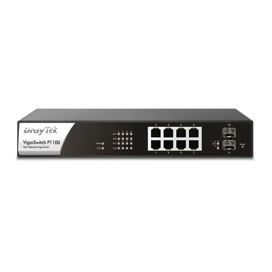
Page 9: Led Indicators And Connectors
No Power Device is connected. Interface Description Power inlet for AC input (100~240V/AC, 50/60Hz). 1/0 (ON/OFF) - Power switch. Power Output IEEE 802.3af Max. 15.4W Output Supported; IEEE 802.3at Max. 30W Output Supported PoE Power Budget 130 Watts (Max) VigorSwitch P1100 User’s Guide... -
Page 10: Hardware Installation
Here VLAN area is defined by what VLAN you are using. The switch supports both port-based VLAN and tag-based VLAN. They are different in practical deployment, especially in physical location. The following diagram shows how it works and what the difference they are. VigorSwitch P1100 User’s Guide... - Page 11 VLAN2 members could not access VLAN1 and VLAN3 members, but they could access VLAN4 members. VLAN3 members could not access VLAN1, VLAN2 and VLAN4. VLAN4 members could not access VLAN1 and VLAN3 members, but they could access VLAN2 members. VigorSwitch P1100 User’s Guide...
- Page 12 Insert the screws and fully tighten with a suitable screwdriver. Repeat the two previous steps for the other side of the unit. Insert the unit into the rack and secure with suitable screws. Reconnect all the cables. VigorSwitch P1100 User’s Guide...
- Page 13 To choose a suitable cable, please refer to the following table. Media Speed Wiring 10 Mbps Category 3,4,5 UTP/STP 10/100/1000 100Mbps Category 5 UTP/STP Mbps copper 1000 Mbps Category 5e, 6 UTP/STP VigorSwitch P1100 User’s Guide...
-
Page 14: Configuring The Management Agent Of Switch
Users can monitor and configure the switch through the following procedures. Configuring the Management Agent of VigorSwitch P1100 through the Ethernet Port. There are two ways to configure and monitor the switch through the switch’s Ethernet port. They are Web browser and SNMP manager. We just introduce the first type of management interface. -
Page 15: Ip Address Assignment
192.168.1.0/24. Each class has its address range described below. Class A: Address is less than 126.255.255.255. There are a total of 126 networks can be defined because the address 0.0.0.0 is reserved for default route and 127.0.0.0/8 is reserved for loopback function. Class B: VigorSwitch P1100 User’s Guide... - Page 16 They are the addresses with all zero’s and all one’s host number. For example, an IP address 128.1.2.128, what IP address reserved will be looked like? All 0s mean the network itself, and all 1s mean IP broadcast. VigorSwitch P1100 User’s Guide...
- Page 17 In this case, subnet mask must be applied. For different network applications, the subnet mask may look like 255.255.255.240. This means it is a small network accommodating a maximum of 15 nodes in the network. VigorSwitch P1100 User’s Guide...
- Page 18 192.168.1.x must be set on your PC. Second, Subnet Mask: as shown above, enter “255.255.255.0”. Any subnet mask such as 255.255.255.x is allowable in this case. Note: The DHCP Setting is enabled in default. VigorSwitch P1100 User’s Guide...
-
Page 19: Typical Applications
The VigorSwitch implements 8 Gigabit Ethernet TP ports with auto MDIX and two slots for the removable module supporting comprehensive fiber types of connection including LC and BiDi-LC SFP modules. The switch is suitable for the following applications. Central Site/Remote site application is used in carrier or ISP VigorSwitch P1100 User’s Guide... - Page 20 It is a system wide basic reference connection diagram. This diagram demonstrates how the switch connects with other network devices and hosts. Peer-to-peer application is used in two remote offices Office network VigorSwitch P1100 User’s Guide...
-
Page 21: Chapter 2: Basic Concept And Management
(MAC), and physical layer. The first two comprises Data link layer, which performs splitting data into frame for transmitting, receiving acknowledge frame, error checking and re-transmitting when not received correctly as well as provides an error-free channel upward to network layer. VigorSwitch P1100 User’s Guide... - Page 22 Information. The DSAP address field identifies the one or more service access points, in which the I/G bit indicates it is individual or group address. If all bit of DSAP is 1s, it’s a global address. The SSAP address field identifies the specific services indicated by C/R bit VigorSwitch P1100 User’s Guide...
-
Page 23: Media Access Control (Mac)
In OSI model, each layer provides its own mean to identify the unique address in some form, for example, IP address in network layer. VigorSwitch P1100 User’s Guide... - Page 24 The SFD pattern is 10101011. Destination address (DA) - The DA field is used to identify which network device(s) should receive the packet. It is a unique address. Please see the section of MAC addressing. VigorSwitch P1100 User’s Guide...
- Page 25 After the frame is assembled, when transmitting the frame, the preamble (PRE) bytes are inserted and sent first, then the next, Start of frame Delimiter (SFD), DA, SA and through VigorSwitch P1100 User’s Guide...
- Page 26 Actually, the practice Gigabit Ethernet chips do not feature this so far. They all have their chips supported full-duplex mode only, as well as all network vendors’ devices. So this criterion should not exist at the present time and in the future. The switch’s Gigabit module supports only full-duplex mode. VigorSwitch P1100 User’s Guide...
- Page 27 What will it be if receiving device is busy and a frame is coming at the same time? Can it use “backpressure” to tell the source device? A function flow control is introduced in the full-duplex operation. VigorSwitch P1100 User’s Guide...
-
Page 28: Flow Control
When the times of collision is increased, the backoff time is getting long until the collision times excess 16. If this happens, the frame will be discarded and backoff time will also be reset. VigorSwitch P1100 User’s Guide... - Page 29 VLAN ID, which are explained respectively in the following table. Bits 15-13 User Priority 7-0, 0 is lowest priority Bit 12 CFI (Canonical Format Indicator) 1: RIF field is present in the tag header 0: No RIF field is present VigorSwitch P1100 User’s Guide...
- Page 30 The maximum length of the extension is equal to the quantity (slotTime - minFrameSize). The MAC continues to monitor the medium for collisions while it is transmitting extension bits, and it will treat any collision that occurs after the threshold (slotTime) as a late collision. VigorSwitch P1100 User’s Guide...
-
Page 31: Chapter 3: Operation Of Web-Based Management
<Apply> button. The login process now would be completed. Web Smart Switch supports a simplified user management function which allows only one administrator to configure the switch at one time. To optimize the display effect, we recommend Microsoft IE and 1024x768 display resolution. VigorSwitch P1100 User’s Guide... -
Page 32: Web Management Home Overview
On the left side, the main menu tree for web is listed in the page. The functions of each folder are described in its corresponded section respectively. As to the function names in normal type are the sub-functions. When clicking it, the function is performed. VigorSwitch P1100 User’s Guide... -
Page 33: Status
MAC address, active subnet mask, active gateway, and etc. Parameter description: System Name System name of the switch. This name will also use as CLI prefix of each line. (“Switch>” or “Switch#”) Set the location of the switch where it was located. System Location VigorSwitch P1100 User’s Guide... -
Page 34: Logging Message
Display the switch logs. Parameter description: Viewing Choose RAM or Flash to display related information. Severity Display the severity of log messages. Description Display the related information about the log. Clear Remove current status. Refresh Refresh current status page. VigorSwitch P1100 User’s Guide... -
Page 35: Port
Parameter description: Port Select one port to show counter statistics. Select the MIB counter to show different count type All: All counters. MIB Counter Interface: Interface related MIB counters Etherlike: Ethernet-like related MIB counters VigorSwitch P1100 User’s Guide... - Page 36 Refresh the web page every period of seconds to get new Refresh Rate counter of specified port. Function name: Status>>Port>>Bandwidth Utilization Function description: Display the Bandwidth Utilization information. Parameter description: Refresh Rate Refresh the web page every period of seconds. VigorSwitch P1100 User’s Guide...
-
Page 37: Link Aggregation
LAG are candidate ports. LACP determines which candidate ports are active member ports. Link State LAG port link status. Active Member Active member ports of the LAG. Inactive Member Inactive or candidate member ports of the LAG. VigorSwitch P1100 User’s Guide... -
Page 38: Mac Address Table
PD priority and power limit. Total Power(W) The system total PoE Power budget. Consuming Power(W) Consuming total PoE power. Allocated Power(W) Allocated PoE power budget by system. Remaining Power(W) Remaining PoE power budget. VigorSwitch P1100 User’s Guide... -
Page 39: Lldp Statistics
The number of times the complete set of information advertised by MSAP has been deleted from tables Age Outs associated with the remote systems because the information timeliness interval has expired. Statistics Table Port Interface or port number. VigorSwitch P1100 User’s Guide... -
Page 40: Igmp Statistics
By listening to these conversations the switch maintains a map of which links need which IP multicast streams. Multicasts may be filtered from the links which do not need them and thus controls which ports receive specific multicast traffic. VigorSwitch P1100 User’s Guide... - Page 41 This field displays the total amount of general query General Query This field displays the total amount of Special Group Special Group Query query TX. Special-specific Group This field displays the total amount of Special-specific Group Query TX. Query VigorSwitch P1100 User’s Guide...
-
Page 42: Network
The switch needs an IP address for it to be managed over the network. The factory default IP address is 192.168.1.224. The subnet mask specifies the network number portion of an IP address. The factory default subnet mask is 255.255.255.0. Parameter description: IPv4 Address VigorSwitch P1100 User’s Guide... - Page 43 Display the optional IPv6 address of the switch. IPv6 Gateway Display the optional IPv6 gateway of the switch. Link Local Address Display the optional IPv6 link local address for the switch. Apply Save the settings or changes to the switch. VigorSwitch P1100 User’s Guide...
-
Page 44: System Time
From Computer – Select the radio button to specify the time from PC. Manual Time – Select the radio button to specify static time manually. Time Zone Select a time zone. SNTP Select Hostname or IPv4. Address Type VigorSwitch P1100 User’s Guide... - Page 45 To - Specify the ending time of recurring daylight saving time. This field available when selecting “Non-Recurring” mode. Operation Status Current Time Display current time the router used. Apply Save the settings or changes to the switch. VigorSwitch P1100 User’s Guide...
-
Page 46: Switching
The factory default for all ports is disabled. A port must be enabled for data transmission to occur. Edit Check for one entry and click Edit to modify the setting. The following shows the configuration page of port setting. VigorSwitch P1100 User’s Guide... - Page 47 When the switch’s auto-negotiation is turned off, a port uses the pre-configured speed and duplex mode when making a connection, thus requiring you to make sure that the settings of the peer port are the same in order to connect. VigorSwitch P1100 User’s Guide...
- Page 48 "collision" signal to the sending port (mimicking a state of packet collision) causing the sending port to temporarily stop sending signals and resend later. Select “Auto”/ “Enable” to enable it. Or select “Disable” to disable it. VigorSwitch P1100 User’s Guide...
-
Page 49: Link Aggregation
Save the settings or changes to the switch. Link Aggregation Table Check to choose a entry. Edit Check for one entry and click Edit to modify the setting. The following shows the configuration page of Link Aggregation Group. VigorSwitch P1100 User’s Guide... - Page 50 Available Port - Inactive or candidate member ports of the LAG. Selected Port - Active member ports of the LAG. Apply Save the settings or changes to the switch. Close Close the page and return to previous page. VigorSwitch P1100 User’s Guide...
- Page 51 Current LAG port speed configuration and link speed Speed status. Duplex Current LAG port duplex configuration and link duplex status. Flow Control Current LAG port flow control configuration and link flow control status. The following shows the configuration page of port setting. VigorSwitch P1100 User’s Guide...
- Page 52 A concentration of traffic on a port decreases port Flow Control bandwidth and overflows buffer memory causing packet VigorSwitch P1100 User’s Guide...
- Page 53 Select “Auto”/ “Enable” to enable it. Or select “Disable” to disable it. Apply Save the settings or changes to the switch. Close Close the page and return to previous page. VigorSwitch P1100 User’s Guide...
- Page 54 Edit to modify the setting. The following shows the configuration page of LACP port setting. Port id could be physical port id or logical port id (trunk id). Mirror, ingress and egress bandwidth control VigorSwitch P1100 User’s Guide...
-
Page 55: Eee
Switching>>EEE Function description: This page allows user to enable or disable port EEE (Energy Efficient Ethernet) function. Parameter description: Port Select one or multiple ports to configure Port EEE function. State Enabled: Enable EEE function. VigorSwitch P1100 User’s Guide... - Page 56 Port EEE admin state. Enable: Check the box to enable port EEE. Disable: Uncheck the box to disable port EEE. Apply Save the settings or changes to the switch. Close Close the page and return to previous page. VigorSwitch P1100 User’s Guide...
-
Page 57: Jumbo Frame
This page allows user to configure switch port jumbo frame settings. Parameter description: Jumbo Frame Check Enable to activate such feature. Type Jumbo frame size. The valid range is 1526 bytes – 9216 bytes. Apply Save the settings or changes to the switch. VigorSwitch P1100 User’s Guide... -
Page 58: Poe
Displays current PoE power consumption. Displays PSE maximum power. Max Power(W) Class 0 : 16.2W Class 1 : 4.2W Class 2 : 7.4W Class 3 : 16.2W Class 4 : 31.2W Max Current(mA) Displays current PoE power current. VigorSwitch P1100 User’s Guide... - Page 59 The factory default for all ports is disabled. Edit Check for one entry and click Edit to modify the setting. Port Display Port Name. PD Priority Display PD Priority. The following shows the configuration page of PoE setting. VigorSwitch P1100 User’s Guide...
- Page 60 Selected the power delivery of watts. 15W: PoE port limit set to 15W (802.3af). 30W: PoE port limit set to 30W (802.3at). Apply Save the settings or changes to the switch. Close Close the page and return to previous page. VigorSwitch P1100 User’s Guide...
-
Page 61: Vlan Management
VLAN entry. Edit Check for one entry and click Edit to modify VLAN. Delete Check for one entry and click Delete to remove VLAN. The following shows the modification page of VLAN name. VigorSwitch P1100 User’s Guide... - Page 62 Forbidden: Specify the port is forbidden in the VLAN. Tagged: Specify the port is tagged in the VLAN. Untagged: Specify the port is untagged in the VLAN. PVID It will be enabled/disabled according to the membership VigorSwitch P1100 User’s Guide...
- Page 63 Display the interface VLAN mode of this port. Administrative VLAN Display the administrative VLAN list of this port. Display the operational VLAN list of this port. Operational VLAN Edit Click the Edit button to edit the VLAN membership of this port. VigorSwitch P1100 User’s Guide...
- Page 64 VLAN ID for this port. Function name: Switching>>VLAN>>VLAN>>Port Setting Function description: This page allow user to configure port VLAN settings such as VLAN port mode, PVID etc… The attributes depend on different VLAN port mode. VigorSwitch P1100 User’s Guide...
- Page 65 Trunk mode. Accept Frame Type Specify the acceptable-frame-type of the specified interfaces. It’s only available with Hybrid mode. Ingress Filtering Specify the status of ingress filtering. It’s only available with Hybrid mode. VigorSwitch P1100 User’s Guide...
- Page 66 Select a value that will be advertised by LLDP-MED. Aging Time Select value of aging time (30~65536 min). Default is 1440 minutes. A voice VLAN entry will be age out after this time if without any packet pass through. VigorSwitch P1100 User’s Guide...
- Page 67 OUIs in the source MAC address. All: QoS attributes are applied to packets that are classified to the Voice VLAN. Apply Save the settings or changes to the switch. Close Close the page and return to previous page. VigorSwitch P1100 User’s Guide...
- Page 68 Description: Input description of the specified MAC address to the voice VLAN OUI table. Edit Check for one entry and click Edit to modify OUI setting for voice VLAN. Delete Click it to remove the selected voice VLAN entry. VigorSwitch P1100 User’s Guide...
-
Page 69: Multicast
Save the settings or changes to the switch. Function name: Switching>>Multicast>>General>>Group Address Function description: To display Multicast General Group web page. This page allow user to browse all multicast groups that dynamic learned or statically added. VigorSwitch P1100 User’s Guide... - Page 70 Edit Check of a group address profile and click Edit to modify settings. Delete Click it to remove the selected group address profile. Refresh Click it to renew current page. Function name: Switching>>Multicast>>General>>Router Port Function description: VigorSwitch P1100 User’s Guide...
- Page 71 Parameter description: State Check Enable to set the enabling status of IGMP functionality. Version Set the IGMP snooping version. IGMP IGMPv2: Only support process v2 packet. VigorSwitch P1100 User’s Guide...
- Page 72 Click Edit to edit the IGMP Snooping Table. Edit Check to select VLAN profile for IGMP. Edit Check of a VLAN profile and click Edit to modify settings. The following shows the modification page of IGMP Snooping VLAN port setting. VigorSwitch P1100 User’s Guide...
- Page 73 Last Member Query The admin last member query interval. Interval Operational Status A brief table for the above settings. Apply Save the settings or changes to the switch. Close Close the page and return to previous page. VigorSwitch P1100 User’s Guide...
- Page 74 The following shows the modification page for VLAN IGMP Snooping querier settings. Parameter description: VLAN ID Display the VLAN ID. State Check Enable to set the enabling status of IGMP Querier Election on the chosen VLAN. VigorSwitch P1100 User’s Guide...
- Page 75 Valid - The valid IGMP Snooping process packet. InValid - The invalid IGMP Snooping process packet. Other - The ICMP protocol is not 2, and is not IPv4 multicast data packet. Leave - IGMP leave packet. VigorSwitch P1100 User’s Guide...
- Page 76 General Query - IGMP general query packet includes querier transmit general query packet. Special Group Query - IGMP special group query packet include querier transmit special group query packet. Source - IGMP special source and group general query packet. VigorSwitch P1100 User’s Guide...
-
Page 77: Spanning Tree
RSTP: Enable the Rapid Spanning Tree (RSTP) operation Path Cost Specify the path cost method. Long: Specifies that the default port path costs are within the range: 1~200,000,000. Short: Specifies that the default port path costs are within VigorSwitch P1100 User’s Guide... - Page 78 Operational root port of the switch. Root Path Cost Operational root path cost. Topology Change Count Numbers of the topology changes. Last Topology Change The last time for the topology change. Apply Save the settings or changes to the switch. VigorSwitch P1100 User’s Guide...
- Page 79 Designated Bridge Designated Port ID The designated port ID on the switch. Designated Cost The path cost of the designated port on the switch. The following shows the modification page of port setting for spanning tree. VigorSwitch P1100 User’s Guide...
- Page 80 STP state change. Point-to-Point Specify the Point-to-Point port configuration: Auto: The state is depended on the duplex setting of the port. Enable: Click it to force to true state. Disable: Click it to force to false state. VigorSwitch P1100 User’s Guide...
- Page 81 2 network, only one path can be taken. Parameter description: Refresh Rate The option to refresh the statistics automatically. Check to select VLAN profile for querier. Port It displays the port number. Receive BPDU(Config) The counts of the received CONFIG BPDU. VigorSwitch P1100 User’s Guide...
-
Page 82: Mac Address Table
MAC Address Table>>Dynamic Address Function description: Parameter description: Aging Time <10-630> The Dynamic MAC address aging out value. Apply Save the settings or changes to the switch. Dynamic Address Table Check to select VLAN profile for querier. VigorSwitch P1100 User’s Guide... -
Page 83: Static Address
MAC entries. If not select any port, VLAN and MAC address, the whole static MAC table will be displayed or cleared. This field displays the port number defined for such Port VLAN. Click it to create a new profile. VigorSwitch P1100 User’s Guide... - Page 84 Check to select VLAN profile and click this button to Edit modify the settings. Check to select VLAN profile and click this button to Delete delete the profile. VigorSwitch P1100 User’s Guide...
-
Page 85: Security
Management VLAN has the same VLAN of management VLAN are allow connecting to device. Others will be dropped. Save the settings or changes to the switch. Apply Function name: Security>>Access Control>>Management Service Function description: Parameter description: VigorSwitch P1100 User’s Guide... -
Page 86: Protected Port
Port List Select the port to be protected. State Configure port protect type: Unprotected: Unprotected port can communicate with all ports. Protected: Prevent protected ports from communicate with each other. Check to select port profile. VigorSwitch P1100 User’s Guide... -
Page 87: Storm Control
Exclude: exclude preamble & IFG (20 bytes) when count ingress storm control rate. Include: include preamble & IFG (20 bytes) when count ingress storm control rate. Apply Save the settings or changes to the switch. Port Setting Table VigorSwitch P1100 User’s Guide... - Page 88 This field displays the port number of physical port. Port State Determine the state of setting. Enable: Check the box to enable the storm control function for the selected Port. Uncheck the box to disable the storm control function for the selected Port. VigorSwitch P1100 User’s Guide...
-
Page 89: Dos
The DoS protection feature is a set of predefined rules that protect the network from malicious attacks. The DoS Security Suite Setting enables activating the security suite. Function name: Security>>DoS>>Property Function description: This page allows user to configure DoS setting to enable/disable DoS function for Global Setting. VigorSwitch P1100 User’s Guide... - Page 90 DoS setting. UDP Blat Drops the packets if the UDP source port equals to the UDP destination port. Enable: Check the box to enable the item DoS setting; uncheck the box to disable the item DoS setting. VigorSwitch P1100 User’s Guide...
- Page 91 : Check the box to enable the item DoS setting for IPv4; uncheck the box to disable the item DoS setting. Enable IPv6: Check the box to enable the item DoS setting for IPv6; uncheck the box to disable the item DoS VigorSwitch P1100 User’s Guide...
- Page 92 0 to 323 bytes, and default length is 0 byte. Enable: Check the box to enable the item DoS setting; uncheck the box to disable the item DoS setting. Save the settings or changes to the switch. Apply VigorSwitch P1100 User’s Guide...
- Page 93 To configure and display the state of DoS protection for interfaces. Parameter description: Check to select port profile. Port This field displays the port number. State Display the port setting is enabled or disabled. Edit Check of a port profile and click Edit to modify settings. VigorSwitch P1100 User’s Guide...
-
Page 94: Qos
CoS value if there is no VLAN tag on the incoming packet. DSCP: All IP traffic is mapped to queues based on the DSCP field in the IP header. If traffic is not IP traffic, VigorSwitch P1100 User’s Guide... - Page 95 Port DSCP remarking admin state. Enable: DSCP remarking is enabled. Disable: DSCP remarking is disabled. Remarking (IP Port IP Precedence remarking admin state. Precedence) Enable: IP Precedence remarking is enabled. Disable: IP Precedence remarking is disabled. VigorSwitch P1100 User’s Guide...
- Page 96 Check Enable to enable CoS remark. DSCP Check Enable to enable DSCP remark. IP Precedence Check Enable to enable IP Precedence remark. Apply Save the settings or changes to the switch. Close Close the page and return to previous page. VigorSwitch P1100 User’s Guide...
- Page 97 Click it to set queue to strict priority type. Click it to set queue to Weight round robin type. Weight If the queue type is WRR, set the queue weight for the queue. Apply Save the settings or changes to the switch. VigorSwitch P1100 User’s Guide...
- Page 98 Class of service value. Queue Select queue ID for the CoS value. Queue of CoS Mapping Queue Queue ID. Class of service Select CoS Value for the Queue ID. Apply Save the settings or changes to the switch. VigorSwitch P1100 User’s Guide...
- Page 99 The DSCP range is 0 to 63. Queue Select queue ID for the DSCP value. Queue to DSCP Mapping Queue Queue ID. DSCP Select DSCP Value for the Queue ID. Apply Save the settings or changes to the switch. VigorSwitch P1100 User’s Guide...
- Page 100 Queue Select queue ID for the IP Precedence value. Queue to IP Precedence Mapping Queue Queue ID. IP Precedence Select IP Precedence value for the queue ID. Apply Save the settings or changes to the switch. VigorSwitch P1100 User’s Guide...
-
Page 101: Rate Limit
Rate – Display the value for Ingress port. Egress State – Display current status (enabled/disabled) of Egress port setting. Rate – Display the value for Egress port. Edit Check of a port profile and click Edit to modify settings. VigorSwitch P1100 User’s Guide... - Page 102 Ingress Type the rate value,<0-1000000>,unit:16 Kbps. Egress Enable - Enable egress bandwidth control. Type the rate value,<0-1000000>,unit:16 Kbps. Apply Save the settings or changes to the switch. Close the page and return to previous page. Close VigorSwitch P1100 User’s Guide...
- Page 103 Check to select port profile. State – Display the egress bandwidth control is Queue 1 ~ 8 enabled/disabled. CIR(Kbps) – Display the Rate value. Edit Check of a port profile and click Edit to modify settings. VigorSwitch P1100 User’s Guide...
- Page 104 Queue 1 ~ 8 Enable – Click it to enable egress bandwidth control. Type the Rate value,<0-1000000>,unit:16 Kbps. Apply Save the settings or changes to the switch. Close Close the page and return to previous page. VigorSwitch P1100 User’s Guide...
-
Page 105: Management
Select the delay before a re-initialization (range 1–10 seconds, default = 2). Transmit Delay Select the delay after an LLDP frame is sent (range 1–8192 seconds, default = 3). Apply Save the settings or changes to the switch. VigorSwitch P1100 User’s Guide... - Page 106 Select specified port or all ports to configure LLDP state. Mode Select the transmission state of LLDP port interface. Disable: Disable the transmission of LLDP PDUs. RX Only: Receive LLDP PDUs only. TX Only: Transmit LLDP PDUs only. Normal: Transmit and receive LLDP PDUs both. VigorSwitch P1100 User’s Guide...
- Page 107 Select the LLDP optional TLVs to be carried (multiple selection is allowed). Port Description System Name System Description System Capability 802.3 MAC-PHY 802.3 Link Aggregation 802.3 Maximum Frame Size VigorSwitch P1100 User’s Guide...
- Page 108 802.1 PVID 802.1 VLAN Name Select the VLAN Name ID to be carried (multiple selection is allowed). Save the settings or changes to the switch. Apply Close Close the page and return to previous page. VigorSwitch P1100 User’s Guide...
- Page 109 Available (Bytes) Total number of available bytes left for additional LLDP information in each packet. Operational Status Overloading or not. Detail Click of a port profile and click “Detail” to view selected port detailed information. VigorSwitch P1100 User’s Guide...
- Page 110 Display the type of chassis ID, such as the MAC Chassis ID Subtype address. Chassis ID Display Identifier of chassis. Where the chassis ID subtype is a MAC address, the MAC address of the switch is displayed. System Name Display name of switch. VigorSwitch P1100 User’s Guide...
- Page 111 Function name: Management>>LLDP>>Neighbor Function description: This page is used to view LLDP neighbor’s information. Parameter description: Check to select port profile. Local Port Number of the local port to which the neighbor is VigorSwitch P1100 User’s Guide...
- Page 112 The Link Layer Discovery Protocol (LLDP) Statistics page displays summary and per-port information for LLDP frames transmitted and received on the switch. Parameter description: Insertions The number of times the complete set of information advertised by a particular MAC Service Access Point VigorSwitch P1100 User’s Guide...
-
Page 113: Snmp
SNMP is a component of the Internet Protocol Suite as defined by the Internet Engineering Task Force (IETF). It consists of a set of standards for network management, including an application layer protocol, a database schema, and a set of data objects. An SNMP-managed network consists of three key components: VigorSwitch P1100 User’s Guide... - Page 114 Click Add to add any other community. Apply - Save the settings or changes to the switch. Close - Close the page and return to previous page. Delete Click Delete to remove any selected community strings. VigorSwitch P1100 User’s Guide...
- Page 115 Server Address Display the IP address of SNMP server. Version Display the SNMP version (SNMPv1 or SNMPv2). Type Display the type (Trap or Inform) selected for the server. SNMP community name for notification. Community VigorSwitch P1100 User’s Guide...
- Page 116 Trap: Send SNMP traps to the host. Inform: Send SNMP informs to the host. Community Choose one of the community profiles (created by Management>>SNMP>>Community). Apply Save the settings or changes to the switch. Close Close the page and return to previous page. VigorSwitch P1100 User’s Guide...
-
Page 117: Diagnostics
If the logging service is disabled, no messages will be sent to these destinations. Minimum Severity Select severity of log messages which will be stored. Apply Save the settings or changes to the switch. Function name: VigorSwitch P1100 User’s Guide... - Page 118 Create a new server profile. Edit Check of a server profile and click Edit to modify settings. Delete Click Delete to remove any selected remote server. The following shows the setting page by clicking Add. Parameter description: VigorSwitch P1100 User’s Guide...
-
Page 119: Mirroring
Function description: To display the Port Mirroring web page. Parameter description: Click it to select port profile. Display mirror session ID. Session ID Select mirror session state: port-base mirror or disable. State Enabled: Enable port based mirror. VigorSwitch P1100 User’s Guide... - Page 120 Select mirror session monitor port, and select. Whether Monitor Port normal packet could be sent or received by monitor port. Ingress Port Select mirror session source RX ports. Egress Port Select mirror session source TX ports. VigorSwitch P1100 User’s Guide...
-
Page 121: Ping
Enter a number between 1 and 5 as the count and the default configuration is 4. Ping Perform ping action. Stop Terminate ping action. Ping Result After ping finished, results will be shown in this field. VigorSwitch P1100 User’s Guide... -
Page 122: Copper Test
Function description: This page allows user to add or delete local user on switch database for authentication. The default user is “admin”. Parameter description: Check to select community profile. Username Display the username for new account. VigorSwitch P1100 User’s Guide... -
Page 123: Firmware Upgrade/Backup
Maintenance >>Firmware>>Upgrade/Backup Function description: This page allows user to upgrade / backup the firmware image or configuration file on the switch to remote TFTP server or host file system through HTTP protocol. Upgrade/Backup files with TFTP Page VigorSwitch P1100 User’s Guide... - Page 124 IP address of the TFTP server Server Address must be assigned. Firmware image or configuration file name on remote Filename TFTP server. If the TFTP upgrade method is selected, the file name must be specified. VigorSwitch P1100 User’s Guide...
-
Page 125: Configuration
This page allows user to save either the running configuration or the startup configuration to the existing configuration file as the startup configuration. Upgrade/Backup files through TFTP Page Upgrade/Backup files through HTTP Page Parameter description: Configuration operations Action VigorSwitch P1100 User’s Guide... - Page 126 If the HTTP upgrade method is selected, the field allows you to select any file on host operating system. Save the settings or changes to the switch. Apply Function name: Maintenance >> Configuration >>Save Configuration Function description: Parameter description: Select upgrade method. Source File VigorSwitch P1100 User’s Guide...
-
Page 127: Factory Default / System Reboot
Function name: Maintenance>>Factory Default Maintenance>>System Reboot Function description: Click Restore Factory Default to return to factory default settings for Vigor switch or click Reboot to reboot Vigor router with current settings. VigorSwitch P1100 User’s Guide... - Page 128 This page is left blank. VigorSwitch P1100 User’s Guide...
-
Page 129: Chapter 4: Trouble Shooting
STP --> STP Global Setting --> Global Setting --> BPDU Forward --> flooding to filter. Answer: RSTP equals to Rapid Spanning Tree. Please follow the following direction to choose it: STP --> STP Global Setting --> Global Setting --> Force Version --> RSTP. VigorSwitch P1100 User’s Guide...
Need help?
Do you have a question about the VigorSwitch P1100 and is the answer not in the manual?
Questions and answers