
Related Manuals for Draytek VIGORSWITCH P2260


Summary of Contents for Draytek VIGORSWITCH P2260
- Page 1 VigorSwitch P2260 User’s Guide Version: 1.0 Date: 2008/12/08 Cop27 yright 2008 All rights reserved.
-
Page 2: Copyright Information
Web registration is preferred. You can register your Vigor device via Owner http://www.draytek.com. Firmware & Tools Due to the continuous evolution of DrayTek technology, all devices will be regularly Updates upgraded. Please consult the DrayTek web site for more information on newest firmware, tools and documents. -
Page 3: Regulatory Information
This device complies with Part 15 of the FCC Rules. Operation is subject to the following two conditions: (1) This device may not cause harmful interference, and (2) This device may accept any interference received, including interference that may cause undesired operation. VigorSwitch P2260 User’s Guide... -
Page 4: Table Of Contents
1.5 Hardware Installation ... 7 1.5.1 Connecting the SFP Fiber Transceiver to the Chassis ... 7 1.5.2 Installing Optional SFP Fiber Transceivers to the switch ... 8 1.5.3 Installing Chassis to a 19-Inch Wiring Closet Rail ... 8 1.5.4 Cabling Requirements ... 8 1.5.5 Configuring the Management Agent of Switch ... - Page 5 2.18.2 VIP ... 102 2.18.3 802.1p ... 103 2.18.4 D-Type TOS... 104 2.18.5 T-Type TOS ... 105 2.18.6 R-Type TOS... 106 2.18.7 M-Type TOS ... 107 2.18.8 DSCP... 108 2.19 Diagnostics... 109 2.19.1 Diagnostics ... 109 VigorSwitch P2260 User’s Guide...
- Page 6 2.19.2 Loopback Test ... 110 2.19.3 Ping Test... 110 2.20 TFTP Server... 111 2.21 Log ...112 2.22 Firmware Upgrade ...113 2.23 Reboot...114 2.24 Logout ...114 Trouble Shooting ... 116 3.1 Resolving No Link Condition...116 3.2 Q & A ...116 VigorSwitch P2260 User’s Guide...
-
Page 7: Preface
In this user’s manual, it will not only tell you how to install and connect your network system but configure and monitor the VigorSwitch P2260 through the built-in CLI and web by RS-232 serial interface and Ethernet ports step-by-step. Many explanations in detail of hardware and software functions are shown as well as the examples of the operation for web-based interface and command-line interface (CLI). -
Page 8: Features
IP multicast packets are running over the network. The VigorSwitch P2260 with 2 SFP Dual Media, a standalone off-the-shelf switch, provides the comprehensive features listed below for users to perform system network administration and efficiently and securely serve your network. - Page 9 In 24-Port PoE L2 Managed Fast Ethernet Switch with 2 SFP Dual Media switch, it supports 2 Gigabit dual media ports(TP/SFP) and 2 slots for removable SFP module supporting 1000M SFP fiber module Supports on-line pluggable fiber transceiver modules Supports 256KB packet buffer and 128KB control memory Maximal packet length can be up to 1536 bytes Full-duplex flow control (IEEE802.3x) and half-duplex backpressure...
-
Page 10: Packing List
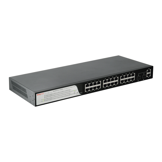
Please notify your sales representative immediately if any of the aforementioned items is missing or damaged. In the switch, Port 25~26 includes two types of media --- TP and SFP Fiber (LC, BiDi LC…); this port supports 10/100/1000Mbps TP or 1000Mbps SFP Fiber with auto-detected function. - Page 11 There are 24 TP Fast Ethernet ports and 2 slots for optional removable modules on the front panel of the switch. LED display area, locating on the front panel, contains a ACT, Power LED and 26 ports working status of the switch.
- Page 12 One RS-232 DB-9 interface is offered for configuration or management. VigorSwitch P2260 User’s Guide...
-
Page 13: Hardware Installation
RJ-45 jack 1, 2, 3, 6 to 3, 6, 1, 2) can be used. It means you do not have to tell from them, just plug it. 1. Use Cat. 5 grade RJ-45 TP cable to connect to a TP port of the switch and the other end is connected to a network-aware device such as a workstation or a server. -
Page 14: Installing Optional Sfp Fiber Transceivers To The Switch
1. Wear a grounding device for electrostatic discharge. 2. Screw the mounting accessory to the front side of the switch (See Fig. 2-2). 3. Place the Chassis into the 19-inch wiring closet rail and locate it at the proper position. - Page 15 WDM Module Takes the Delay Time into Account Theoretically, the switch partitions the collision domain for each port in switch cascading that you may up-link the switches unlimitedly. In practice, the network extension (cascading levels & overall diameter) must follow the constraint of the IEEE 802.3/802.3u/802.3z and other 802.1 series protocol specifications, in which the limitations...
- Page 16 If more than two switches are connected in the same network, select one switch as Level 1 switch and connect all other switches to it at Level 2. Server/Host is recommended to connect to the Level 1 switch. This is general if no VLAN or other special requirements are applied.
- Page 17 The same VLAN members could not be in different switches. Every VLAN members could not access VLAN members each other. The switch manager has to assign different names for each VLAN groups at one switch. Case 3: Port-based VLAN - 2 VLAN1 members could not access VLAN2, VLAN3 and VLAN4 members.
- Page 18 Case 4: The same VLAN members can be at different switches with the same VID VigorSwitch P2260 User’s Guide...
-
Page 19: Configuring The Management Agent Of Switch
We offer you three ways to startup the switch management function. They are RS-232 console, CLI, and Web. Users can use any one of them to monitor and configure the switch. You can touch them through the following procedures. Configuring the Management Agent of VigorSwitch P2260 through the Serial RS-232... - Page 20 VigorSwitch. Set IP Address, Subnet Mask and Default Gateway IP Address You can first either configure your PC IP address or change IP address of the switch, next to change the IP address of default gateway and subnet mask.
- Page 21 Configuring the Management Agent of VigorSwitch P2260 through the Ethernet Port There are three ways to configure and monitor the switch through the switch’s Ethernet port. They are CLI, Web browser and SNMP manager. The user interface for the last one is NMS dependent and does not cover here.
- Page 22 1. Set up a physical path between the configured the switch and a PC by a qualified UTP Cat. 5 cable with RJ-45 connector. Note: If PC directly connects to the switch, you have to setup the same subnet mask between them. But, subnet mask may be different for the PC in the remote site.
-
Page 23: Ip Address Assignment
IP address range between 192.0.0.0 and 223.255.255.255. Each class C network has a 24-bit network prefix followed 8-bit host address. There are 2,097,152 (2^21)/24 networks able to be defined with a maximum of 254 (2^8 –2) hosts per network. VigorSwitch P2260 User’s Guide... - Page 24 They are the addresses with all zero’s and all one’s host number. For example, an IP address 128.1.2.128, what IP address reserved will be looked like? All 0s mean the network itself, and all 1s mean IP broadcast. 10.0.0.0 --- 10.255.255.255 172.16.0.0 --- 172.31.255.255 192.168.0.0 --- 192.168.255.255 VigorSwitch P2260 User’s Guide...
- Page 25 The gateway setting is used for Trap Events Host only in the switch. For assigning an IP address to the switch, you just have to check what the IP address of the network will be connected with the switch. Use the same network address and append your host address to it.
- Page 26 To connect to a server, the client needs to know the IP of the server. However, user generally uses the name to connect to the server. Thus, the switch DNS client program (such as a browser) will ask the DNS to resolve the IP address of the named server.
-
Page 27: Typical Applications
24 Fast Ethernet TP ports with auto MDIX and 2 Gigabit dual media ports with SFP for removable module supported comprehensive fiber types of connection, including LC, BiDi LC for SFP. For more details on the specification of the switch, please refer to Appendix The switch is suitable for the following applications. - Page 28 Daisy-Chain Fiber Network Connection Uninterrupted Power Supply for IP Phone Application VigorSwitch P2260 User’s Guide...
-
Page 29: Operation Of Web-Based Management
TP/SFP Fiber management Ethernet switch. With this facility, you can easily access and monitor through any one port of the switch all the status of the switch, including MIBs status, each port activity, Spanning tree status, port aggregation status, multicast traffic, VLAN and priority status, even illegal access record and so on. -
Page 30: Web Management Home Overview
On the top side, it shows the front panel of the switch. In the front panel, the linked ports will display green; as to the ports, which are link off, they will be dark. For the optional modules, the slot will show only a cover plate if no module exists and will show a module VigorSwitch P2260 User’s Guide... - Page 31 Open the function folder, a sub-menu will be shown. The functions of each folder are described in its corresponded section respectively. When clicking it, the function is performed. The following list is the full function tree for web user interface. VigorSwitch P2260 User’s Guide...
-
Page 32: System Information
Function name: System Information Function description: Show the basic system information. VigorSwitch P2260 User’s Guide... - Page 33 The time accumulated since this switch is powered up. Its format is day, hour, minute, second. Show the system time of the switch. Its format: day of week, month, day, hours: minutes: seconds, year. For instance, Wed, Apr. 23, 12:10:10, 2004.
-
Page 34: Ip Configuration
IP configuration is one of the most important configurations in the switch. Without the proper setting, network manager will not be able to manage or view the device. The switch supports both manual IP address setting and automatic IP address setting via DHCP server. - Page 35 Subnet mask: Default gateway: DNS Server VigorSwitch P2260 User’s Guide <Apply> button to update. When DHCP is disabled, Default: 192.168.1.1 If DHCP is enabled, this field is filled by DHCP server and will not allow user manually set it any more.
-
Page 36: Time Configuration
“Second” within the valid value range indicated in each item. If you input an invalid value, for example, 61 in minute, the switch will clamp the figure to 59. NTP is a well-known protocol used to synchronize the clock of the switch system time over a network. NTP, an internet draft standard formalized in system is version 3 protocol. -
Page 37: Account Configuration
Administrator can modify other guest identities’ password without confirming the VigorSwitch P2260 User’s Guide Time Zone, the switch will sync the time in a short after pressing <Apply> button. Though it synchronizes the time automatically, NTP does not update the time periodically without user’s processing. -
Page 38: Management Policy
Through the management security configuration, the administrator can do the strict setup to control the switch and limit the user to access this switch. The following rules are offered for the administrator to manage the switch: Rule 1) : When no lists exists, then it will accept all connections. - Page 39 VLAN VID is able to be accepted or denied by the switch, the IP range of the user could be accepted or denied by the switch, the port that the user is allowed or not allowed to connect with the switch, or the way of controlling and connecting to the switch via Http, Telnet or SNMP.
- Page 40 A name is composed of any letter (A-Z, a-z) and digit (0-9) with maximal 8 characters. The switch supports two kinds of options for managed valid VLAN VID, including “Any” and “Custom”. Default is “Any”. When you choose “Custom”, you can fill in VID number.
-
Page 41: Virtual Stack
Virtual Stack Management (VSM) is the group management function. Through the proper configuration of this function, switches in the same LAN will be grouped automatically. And among these switch, one switch will be a master machine, and the others in this group will become the slave devices. - Page 42 It is used for the activation or de-activation of VSM. Default is Disable. The role that the switch would like to play in virtual stack. Two types of roles, including master and slave are offered for option. Default is Master.
-
Page 43: Port Configuration
Port Status Function Description: Report the latest updated status of all ports in this switch. When any one of the ports in the switch changes its parameter displayed in the page, it will be automatically refreshed the port current status about every 5 seconds. - Page 44 It decides that whether the port transmits the PAUSE frame or not. If it shows “on”, the port will send PAUSE frame; otherwise, the port will not send the PAUSE frame. Default: None General information for that port. VigorSwitch P2260 User’s Guide...
-
Page 45: Port Configuration
All of them are described in detail below. Function name: Port Configuration Function description: It is used to set each port’s operation mode. The switch supports 3 parameters for each port. They are state, mode and flow control. Parameter description: State: Speed/Duplex: VigorSwitch P2260 User’s Guide... -
Page 46: Simple Counter
When it is set Asymmetric, this will let the receiving port care the PAUSE frame from transmitting device(s), but it doesn’t send PAUSE frame. This is one-way flow control. Default: Symmetric. Speed Duplex 10/100M Full/Half 10/100/1000M Full for all, Half for 10/100 1000M Full VigorSwitch P2260 User’s Guide... -
Page 47: Detail Counter
Function description: Display the detailed counting number of each port’s traffic. In the Fig. 3-14, the window can show all counter information of each port at one time. VigorSwitch P2260 User’s Guide Total transmitted bytes. Total received bytes. The counting number of the packet transmitted. - Page 48 16 transmission attempts. Number of 64-byte frames in good and bad packets received. Number of 65 ~ 127-byte frames in good and bad packets received. Number of 128 ~ 255-byte frames in good and bad packets received. VigorSwitch P2260 User’s Guide...
-
Page 49: Poe Configuration
Function name: POE Status Function description: Display the information about the PoE status. VigorSwitch P2260 User’s Guide Number of 256 ~ 511-byte frames in good and bad packets received. Number of 512 ~ 1023-byte frames in good and bad packets received. -
Page 50: Poe Configuration
DC Disconnect Port Off: Overload Port Off: Short Circuit Port Off: Over Temp. Protection: Power Management Port Off: Due to total power required by all PDs linked to the switch Function name: POE Configuration Function description: It displays what volt was supplied by the Switch. -
Page 51: Loop Detection
The switch complies with IEEE 802.3af protocol and be capable of detecting automatically that whether the device linked to the port on the switch is PD (Powered Device) or not. The switch also manage the power supplement based on the Class of the PD, and it will stop supplying the power once the power required by the PD excesses the Class, Short Circuit or over temperature occurs. -
Page 52: Snmp Configuration
The SNMP is a protocol that is used to govern the transfer of information between SNMP manager and agent and traverses the Object Identity (OID) of the management Information Base (MIB), described in the form of SMI syntax. SNMP agent is running on the switch to response the request issued by SNMP manager. - Page 53 Basically, it is passive except issuing the trap information. The switch supports a switch to turn on or off the SNMP agent. If you set the field SNMP “Enable”, SNMP agent will be started up. All supported MIB OIDs, including RMON MIB, can be accessed via SNMP manager.
- Page 54 Default trap host IP address: 0.0.0.0 Default port number:162 Trap: In the switch, there are 6 trap hosts supported. Each of them has its own community name and IP address; is user-definable. To set up a trap host means to create a trap manager by assigning an IP address to host the trap message.
-
Page 55: Dhcp Boot
At this moment, a bunch of switch or other network device on the LAN will try its best to find the server to get the services or try to set up the predefined links, they will issue many broadcast packets in the network. - Page 56 Passive - In Passive Snooping mode, the IGMP snooping will not periodically poll the hosts in the groups. The switch will send a Membership Query message to all hosts only when it has received a Membership Query message from a router.
-
Page 57: Allowed Group
VID: Port: Add: Edit: VigorSwitch P2260 User’s Guide The switch supports two kinds of options for managed valid IP range, including “Any” and “Custom”. Default is “Any”. In case that “Custom” had been chosen, you can assigned effective IP range. The valid range is 224.0.0.0~239.255.255.255. -
Page 58: Static Ip Multicast
Set member ports that join each multicast group. Member port may be only or more than one. Create a new Static IP Multicast group entry. Modify a Static IP Multicast group entry. Remove a static IP Multicast group entry. Support 256 active VLANs VigorSwitch P2260 User’s Guide... -
Page 59: Vlan
2&3&4. If you are on the port 5, then you cannot talk to them. Each port-based VLAN you built up must be assigned a group name. This switch can support up to maximal 8 port-based VLAN groups. - Page 60 VID”.). For example, if port 1 receives a tagged packet with VID=100 (VLAN name=VLAN100), and if Symmetric-Vlan function is enabled, the switch will check if port 1 is a member of VLAN100. If yes, the received packet is forwarded; otherwise, the received packet is dropped.
-
Page 61: Tag-Based Group
VID: VigorSwitch P2260 User’s Guide Except Port 25 and Port 26, each port of the switch cannot transmit packets with each other. Each port groups a VLAN with Port 25 and Port 26, thus, total 6 groups consisting of 3 members are formed.4... -
Page 62: Pvid
Untagged-frames. Just press the <Delete> button to remove the selected group entry from the Tag-based group table. Just select a group entry and press the <Edit> button, then you can modify a group’s description. VigorSwitch P2260 User’s Guide... -
Page 63: Port-Based Group
PVID, you have to create a Tag-based VLAN with VID x. For example, if port x receives an untagged packet, the switch will apply the PVID (assume as VID y) of port x to tag this packet, the packet then will be forwarded as the tagged packet with VID y. - Page 64 VLAN. Just tick the check box ( the port x to enable it. Just press the <Delete> button to remove the selected group entry from the Port-based group table. “ and “_” beside VigorSwitch P2260 User’s Guide...
-
Page 65: Management Vlan
To create a secure VLAN for the switch management interface, all of the management traffic will be sent via an isolated VLAN. This is a security function. It can protect switch management interface, it also can avoid the switch CPU DoS by network attacking. -
Page 66: Mac Table
Save the Alias of MAC entry you set up. Find the entry that meets your setup. Move to the previous page. Move to the next page. The Alias of the searched entry. The MAC address of the searched entry. VigorSwitch P2260 User’s Guide... -
Page 67: Mac Table Maintenance
Parameter description: Aging Time: Flush: Learning Limit VigorSwitch P2260 User’s Guide The port that exists in the searched MAC Entry. VLAN Group that MAC Entry exists. Display the method that this MAC Entry is built. It may show “Dynamic MAC” or “Static MAC”. -
Page 68: Static Forward
As “static” is chosen, assign a MAC address to a specific port, all of the switch’s traffics sent to this MAC address will be forwarded to this port. -
Page 69: Mac Alias Create/Edit Or Delete
Alias: VigorSwitch P2260 User’s Guide dropped. Select the port No. you would like to do setup in the switch. It is 1~26. It is a six-byte long Ethernet hardware address and usually expressed by hex and separated by hyphens. For example, 00 –... -
Page 70: Gvrp Configuration
Parameter description: GVRP State Setting: This function is simply to let you enable or disable GVRP function. You can pull down the list and click the <Downward> arrow key to choose “Enable” or “Disable”. VigorSwitch P2260 User’s Guide... - Page 71 Enabled - In this mode, the switch does not create dynamic VLAN when this port received GVRP PDU. Except received dynamic VLAN message of the GVRP PDU is an existed static VLAN in the switch, this port will be added into the static VLAN members dynamically.
-
Page 72: Gvrp Counter
Leave Empty message is received by the GARP application. Empty Message Packets - Number of GARP BPDU with Empty message is received by the GARP application. Total GVRP Packets - Total GARP BPDU is transmitted by the GVRP application. VigorSwitch P2260 User’s Guide... -
Page 73: Gvrp Group Information
Show the dynamic group member and their information. Parameter description: VID: Member Port: VigorSwitch P2260 User’s Guide Invalid GVRP Packets - Number of invalid GARP BPDU is transmitted by the GVRP application. LeaveAll Message Packets - Number of GARP BPDU with Leave All message is transmitted by the GARP application. -
Page 74: Stp Configuration
User can enable Spanning Tree Protocol on switch’s web management and then set up other advanced items. We recommend that you enable STP on all switches to ensure a single active path on the network. -
Page 75: Stp Configuration
Function name: STP Configuration Function description: VigorSwitch P2260 User’s Guide Show the current root bridge priority. Show port number connected to root bridge with the lowest path cost. Show the path cost between the root port and the designated port of the root bridge. - Page 76 User can set the following Spanning Tree parameters to control STP function enable/disable, select mode RSTP/STP and affect STP state machine behavior to send BPDU in this switch. The default setting of Spanning Tree Protocol is “Disable”. Parameter description: Spanning Tree Protocol:...
-
Page 77: Stp Port Configuration
Two options are offered for the user’s choosing STP algorithm. One is RSTP and the other is STP. If STP is chosen, RSTP will run as a legacy STP. The switch supports RSTP (802.1w) which is backward compatible with STP (802.1d). - Page 78 A port with a smaller path cost value would become the Root Port more possibly. The range is 0 – 200,000,000. In the switch, if path cost is set to be zero, the STP will get the recommended value resulted from auto-negotiation of the link accordingly and display this value in the field of Path Cost Status.
-
Page 79: Trunking Configuration
Operating in half-duplex mode Aggregate the ports with different data rates VigorSwitch P2260 User’s Guide We say a port is a point-to-point link, from RSTP’s view, if it is in full-duplex mode but is shared link if it is in half-duplex mode. -
Page 80: Port Setting/Status
“not ready” state when using static trunk to aggregate with high speed links. As to system restrictions about the port aggregation function on the switch, in the management point of view, the switch supports maximum 8 trunk groups for LACP and additional 8 trunk groups for Static Trunk. - Page 81 Method: Group: Active LACP: Aggtr: Status: VigorSwitch P2260 User’s Guide This determines the method a port uses to aggregate with other ports. None - A port does not want to aggregate with any other port should choose this default setting.
-
Page 82: Aggregator View
ID is the same as its own Port No.. Show the method a port uses to aggregate with other ports. Show all member ports of an aggregator (port). Show only the ready member ports within an aggregator (port). VigorSwitch P2260 User’s Guide... - Page 83 MAC Address: Port: Key: Trunk Status: VigorSwitch P2260 User’s Guide The switch you are watching on. The peer system from this aggregator’s view. Show the System Priority part of a system ID. Show the MAC Address part of a system ID.
-
Page 84: Lacp System Priority
1 to 65535. Default: 32768. DA+SA, DA and SA are three Hash methods offered for the Link Aggregation of the switch. Packets will decide the path to transmit according to the mode of Hash you choose. Default: DA and SA... - Page 85 PAE. The Authenticator exchanges the message to authentication server using EAP encapsulation. Before successfully authenticating, the supplicant can only touch the authenticator to perform authentication message exchange or access the network from the uncontrolled port. VigorSwitch P2260 User’s Guide...
- Page 86 If success, the authentication server will notice the authenticator the grant. PC A, then, is allowed to access B and C via the switch. If there are two switches directly connected together instead of single one, for the link connecting two switches, it may have to act two port roles at the end of the link: authenticator and supplicant, because the traffic is bi-directional.
- Page 87 EAPOL and the left side is EAP. 1. At the initial stage, the supplicant A is unauthenticated and a port on switch acting as an authenticator is in unauthorized state. So the access is blocked in this stage.
- Page 88 10. When the supplicant issue an EAP-Logoff message to Authentication server, the port you are using is set to be unauthorized. Only MultiHost 802.1X is the type of authentication supported in the switch. In this mode, for the devices connected to this port, once a supplicant is authorized, the devices connected to this port can access the network resource through this port.
-
Page 89: 802.1X State Setting
Port Number: Secret Key: Accounting Service Accounting Server Accounting Port VigorSwitch P2260 User’s Guide RADIUS server IP address for authentication. Default: 192.168.1.1 The port number to communicate with RADIUS server for the authentication service. The valid value ranges 1-65535. Default port number is 1812. -
Page 90: 802.1X Mode Setting
Advanced 802.1x – In this mode, each client under this port has to do 802.1X authentication by himself. VigorSwitch P2260 User’s Guide... -
Page 91: Port Security Management
This function is used to configure the parameters for each port in 802.1X port security application. Refer to the following parameters description for details. VigorSwitch P2260 User’s Guide The port number to be chosen to show its 802.1X Port Status. - Page 92 Default: 2 A time period to transmitted EAPOL PDU between the authenticator and the supplicant. Default: 30 A period of time during which we will not attempt to access the supplicant. Deafult: 60 seconds VigorSwitch P2260 User’s Guide...
-
Page 93: Alarm Configuration
Events Configuration Function description: The Trap Events Configuration function is used to enable the switch to send out the trap information while pre-defined trap events occurred. The switch offers 24 different trap events to users for switch management. The trap information can be sent out in three ways, including email, mobile phone SMS (short message system) and trap. - Page 94 STP Topology Changed, STP Disabled, STP Enabled LACP Disabled, LACP Enabled, LACP Member Added, LACP Port Failure GVRP Disabled, GVRP Enabled VLAN Disabled, Port-based VLAN Enabled, Tag-based VLAN Enabled, Metro-mode Vlan Enabled, Double-tag Vlan Enabled Module Inserted, Module Removed, Dual Media Swapped VigorSwitch P2260 User’s Guide...
-
Page 95: Email/Sms Configuration
Note: SMS may not work in your mobile phone system. It is customized for different systems. Parameter description: Email: SMS: VigorSwitch P2260 User’s Guide Mail Server: the IP address of the server transferring your email. Username: your username on the mail server. Password: your password on the mail server. -
Page 96: Configuration
This is the ex-factory setting and cannot be altered. In Web UI, two restore default functions are offered for the user to restore to the default setting of the switch. One is the function of “Restore Default Configuration included default IP address”, the IP address will restore to default “192.168.1.1”... -
Page 97: Save/Restore
Save As Start Configuration Function description: Save the current configuration as a start configuration file in flash memory. Function name: Save As User Configuration Function description: Save the current configuration as a user configuration file in flash memory. VigorSwitch P2260 User’s Guide... - Page 98 Function description: Restore Default Configuration function can retrieve the ex-factory setting to replace the start configuration. However, the switch’s current IP address that the user set up will not be changed and will NOT be restored to 192.168.1.1 as well.
- Page 99 Restore User Configuration function can retrieve the previous confirmed working configuration stored in the flash memory to update start configuration. When completing to restore the configuration, the system’s start configuration is updated and will be changed its system settings after rebooting the system. VigorSwitch P2260 User’s Guide...
-
Page 100: Config File
Export User-Conf - Export Save As User’s config file stored in the flash. Import Start -Import Save As Start’s config file stored in the flash. Import User-Conf - Import Save As User’s config file stored in the flash. VigorSwitch P2260 User’s Guide... -
Page 101: Security
Monitored Egress Port: Function name: Isolated Group Function description: VigorSwitch P2260 User’s Guide Used for the activation or de-activation of Port Mirror function. Default is “Disable”. Set up the port for monitoring. Valid port is Port 1~26 and default is Port 1. -
Page 102: Bandwidth Management
Just tick the check box ( ) beside the port x and valid port is Port 1~26. In this group, all of these member ports cannot forward packets with each other. Thus, the switch will not be capable of forwarding any packets in case its all ports become the members of the Isolated group. -
Page 103: Egress
Egress Bandwidth Setting function is used to set up the limit of Egress bandwidth for each port. VigorSwitch P2260 User’s Guide Choose the port that you would like this function to work on it. Valid range of the port is 1~26. -
Page 104: Storm
Valid value of Port 1~24 ranges from 66~102400, and Port 25~26 ranges from 66~1024000 with the minimum unit of 1. Default value of Port 1~24 is 102400 and Port 25~26 is 1024000. VigorSwitch P2260 User’s Guide... -
Page 105: Qos(Quality Of Service) Configuration
Storm Type: Storm Rate: The switch supports 5 kinds of QoS, are as follows, MAC Priority, 802.1p Priority, IP TOS Priority, and DiffServ DSCP Priority. Port Based Priority has a special name called VIP Port in the switch. Any packets enter VIP Port will have highest transmitting priority. MAC Priority act on the destination address of MAC in packets. - Page 106 DSCP, and the last two bits are left unused. High Priority Packet streams will experience less delay into the switch. For handing different priority packets, each egress port has designed up to 4 queues. Each QoS is influenced by two scheduling, WRR (Weighted Round Robin) and Strict Priority as well.
-
Page 107: Global
QoS Mode: Priority Control: Scheduling Method: Weight: VigorSwitch P2260 User’s Guide You can Enable QoS Mode and let QoS function become effective. Default is Disable. Just tick the check box ( ) of 802.1P, TOS, or DSCP Qos and click Apply button to be in operation. -
Page 108: Vip
Method of Strict Priority ahead. Parameter description: VIP Group: Just tick the check box ( ) to select any port( port 1~26) as the VIP Port. Then, click the <Apply> button to have the setting taken effect. VigorSwitch P2260 User’s Guide... -
Page 109: 103
This function will affect the priority of VLAN tag. Based on priority of VLAN tag, it can arrange 0~8 priorities, priorities can map to 4 queues of the switch (queue 0~3) and possess different bandwidth distribution according to your weight setting. -
Page 110: D-Type Tos
Priority 3 is mapping to Queue 1, Priority 4 is mapping to Queue 2, Priority 5 is mapping to Queue 2, Priority 6 is mapping to Queue 3, and Priority 0 is mapping to Queue 3. VigorSwitch P2260 User’s Guide... -
Page 111: T-Type Tos
Parameter description: Queue: VigorSwitch P2260 User’s Guide Each Priority can select any of Queue 0 ~ Queue 3. In Default, Priority 0 is mapping to Queue 0, Priority 1 is mapping to Queue 0, Priority 2 is mapping to Queue 1,... -
Page 112: R-Type Tos
Priority 3 is mapping to Queue 1, Priority 4 is mapping to Queue 2, Priority 5 is mapping to Queue 2, Priority 6 is mapping to Queue 3, and Priority 0 is mapping to Queue 3. VigorSwitch P2260 User’s Guide... -
Page 113: M-Type Tos
Parameter description: Queue: VigorSwitch P2260 User’s Guide Each Priority can select any of Queue 0 ~ Queue 3. In Default, Priority 0 is mapping to Queue 0, Priority 1 is mapping to Queue 0, Priority 2 is mapping to Queue 1,... -
Page 114: Dscp
DSCP can form total 64 (0~63) kinds of Traffic Class based on the arrangement of 6-bit field in DSCP of the IP packet. In the switch, user is allowed to set up these 64 kinds of Class that belong to any of queue 0~3. -
Page 115: Diagnostics
Diagnostics function provides a set of basic system diagnosis. It let users know that whether the system is health or needs to be fixed. The basic system check includes EEPROM test, UART test, DRAM test and Flash test. VigorSwitch P2260 User’s Guide... -
Page 116: Loopback Test
Loopback Test and the other is External Loopback Test. The former test function will not send the test signal outside the switch box. The test signal only wraps around in the switch box. As to the latter test function, it will send the test signal to its link partner. If you do not have them connected to active network devices, i.e. -
Page 117: Tftp Server
Specify the IP address where the TFTP server locates. Fill in the IP address of your TFTP server, then press <Apply> button to have the setting taken effect. VigorSwitch P2260 User’s Guide An IP address with the version of v4, e.g. 192.168.1.1. -
Page 118: Log
This function shows the log data. The switch provides system log data for users. There are 19 private trap logs, 5 public trap logs. The switch supports total 120 log entries. For more details on log items, please refer to the section of Trap/Alarm Configuration and SNMP Configuration. -
Page 119: Firmware Upgrade
Software upgrade tool is used to help upgrade the software function in order to fix or improve the function. The switch provides a TFTP client for software upgrade. This can be done through Ethernet. Function name: Firmware Upgrade Function description: The switch supports TFTP upgrade tool for upgrading software. -
Page 120: Reboot
We offer you many ways to reboot the switch, including power up, hardware reset and software reset. You can press the RESET button in the front panel to reset the switch. After upgrading software, changing IP configuration or changing VLAN mode configuration, then you must reboot to have the new configuration taken effect. - Page 121 Parameter description: Auto Logout: VigorSwitch P2260 User’s Guide Default is ON. If it is “ON”, and no action and no key is stroke as well in any function screen more than 3 minutes, the switch will have you logout automatically.
-
Page 122: Trouble Shooting
The connection ports on another must be connection ports. Please check if connection ports are used on that Managed Switch. Please check the uplink setup of the Managed Switch to verify the uplink function is enabled. The COM port default parameters are [Baud Rate: 57600, Data Bits: 8, Parity Bits: None, Stop Bit: A, Flow Control: None]. - Page 123 Check the RS-232 cable is connected well on the console port of the Managed Switch and COM port of PC. Check if the COM of the PC is enabled. The “Hyperterm” is the terminal program in Win95/98/NT. Users can also use any other terminal programs in Linux/Unix to configure the Managed Switch.
Need help?
Do you have a question about the VIGORSWITCH P2260 and is the answer not in the manual?
Questions and answers