
Related Manuals for Draytek VigorSwitch P1280


Summary of Contents for Draytek VigorSwitch P1280
-
Page 2: Quick Start Guide
VigorSwitch P1280 PoE Web Smart Giga Switch Quick Start Guide Version: 1.1 Firmware Version: V2.0.0_RC1a (For future update, please visit DrayTek web site) Date: July 11, 2017... - Page 3 Intellectual Property Rights (IPR) Information © All rights reserved. This publication contains information that is protected Copyrights by copyright. No part may be reproduced, transmitted, transcribed, stored in a retrieval system, or translated into any language without written permission from the copyright holders. The following trademarks are used in this document: Trademarks ...
-
Page 4: Eu Declaration Of Conformity
EU Declaration of Conformity We DrayTek Corp. , office at No.26, Fu Shing Road, HuKou County, Hsin-Chu Industry Park, Hsinchu 300, Taiwan , R.O.C., declare under our sole responsibility that the product Product name: PoE Web Smart Giga Switch ... -
Page 5: Regulatory Information
(2) This device may accept any interference received, including interference that may cause undesired operation. Caution: Any changes or modifications not expressly approved by the party responsible for compliance could void the user's authority to operate the equipment. More update, please visit www.draytek.com. - Page 6 Web registration is preferred. You can register your Vigor switch via http://www.draytek.com. Firmware & Tools Updates Due to the continuous evolution of DrayTek technology, all switches will be regularly upgraded. Please consult the DrayTek web site for more information on newest firmware, tools and...
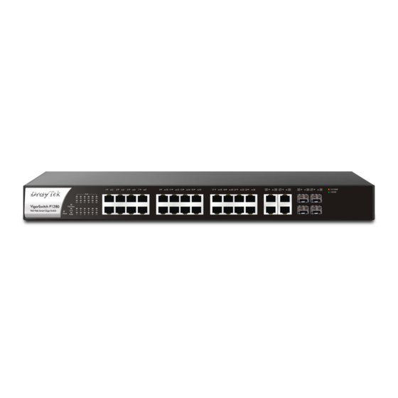
- Page 7 The 24 ports + 4 Combo UTP/SFP ports, PoE Gigabit Ports Web Smart Switch is a standard switch that meets both IEEE 802.3u/ab Fast Ethernet and Gigabit Ethernet specifications. The network administrator can logon the switch to monitor, configure and control each port’s activity.
- Page 8 RJ45 LNK/ACT Port 1 to Port 24 / PoE for Port 1 to Port 24 Combo Port SFP LNK/ACT Status Explanation On (Green) Connected over the PoE maximum power PoE/Max budget. Connected within the PoE maximum power budget. The switch finishes system booting and the On (Green) system is ready.
- Page 9 SFP LNK/ACT On (Green) The device is connected with 1000Mbps. The device is connected with 10/100Mbps. (Amber) Blinking The system is sending or receiving data through the port. The port is disconnected or the link is failed. Interface Description Port 1 to Port 24 can be used for Ethernet RJ 45 LNK/ACT Port 1 ~ 24 connection and PoE connection, depending on PoE for Port 1 ~ 24...
- Page 10 This section will guide you to install the switch through hardware connection and configure the switch’s settings through web browser. Before starting to configure the switch, you have to connect your devices correctly. Note Power the device to this switch and get 48V power source through Cat.
- Page 11 The switch can be installed easily by using rack mount kit. Attach the brackets to the chassis of a 19- or a 23-inch rack. The second bracket attaches the other side of the chassis as above procedure. After the bracket installation, the VigorSwitch’s chassis can be installed in a rack by using four screws for each side of the rack.
- Page 12 Before using the switch, perform the following steps: 1. Set up a physical path between the configured the switch and a PC by a qualified UTP Cat. 5e cable with RJ-45 connector. If a PC directly connects to the switch, you have to setup the same subnet mask for Default values of the managed switch are listed as follows: PC and the switch.
- Page 13 This DrayTek product uses software partially or completely licensed under the terms of the GNU GENERAL PUBLIC LICENSE. The author of the software does not provide any warranty. A Limited Warranty is offered on DrayTek products. This Limited Warranty does not cover any software applications or programs.
Need help?
Do you have a question about the VigorSwitch P1280 and is the answer not in the manual?
Questions and answers