Advertisement
Table of Contents
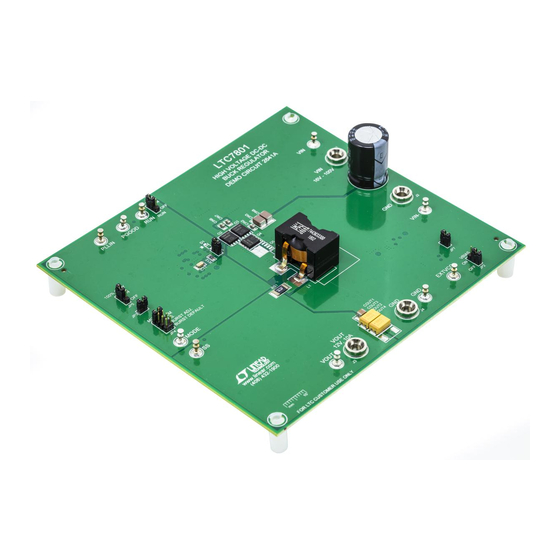
DESCRIPTION
Demonstration circuit 2641A is a single output synchro-
nous buck converter featuring the LTC7801EUFD in the
24-lead QFN package. The input voltage range is from
16V to 100V and the output is 12V/10A. The DC2641A is
configured with a sense resistor for overcurrent protec-
tion. Inductor DCR current sensing is optional.
The board has a lot of features including an optional
onboard NMOS LDO for DRVCC, a switch-mode power
supply for EXTV
, jumper selectable 100% duty cycle
CC
operation in dropout, a mode selector pin that allows
the converter to run in CCM, pulse-skip, adjustable burst
PERFORMANCE SUMMARY
PARAMETER
Input Voltage Range
Output Voltage V
OUT
Maximum Output Current I
OUT,MAX
Default Operating Frequency (Typical)
External Clock Sync. Frequency Range
Typical Full Load Efficiency (See Figure 4)
Synchronous Buck Converter
Specifications are at T
CONDITIONS
V
= 16~100V, I
= 0~10A, JP4: FCM
IN
OUT
V
= 16~100V
IN
V
= 48V, V
= 12V, I
= 10A, f
IN
OUT
OUT
DEMO MANUAL DC2641A
High Input Voltage
clamp or default Burst Mode
voltage monitor and PLLIN for PolyPhase
The
LTC7801
data sheet gives a complete description
of the part, operation and application information and
must be read in conjunction with this demo manual for
DC2641A.
Design files for this circuit board are available at
http://www.linear.com/demo/DC2641A
L, LT, LTC, LTM, Linear Technology, Burst Mode, PolyPhase and the Linear logo are registered
trademarks of Analog Devices, Inc. All other trademarks are the property of their respective
owners.
= 25°C
A
VALUE
16V ~ 100V
12V ± 2% (11.76V ~ 12.24V)
10A
150kHz
75kHz – 850kHz
= 150 kHz
95.3%
SW
LTC7801EUFD
®
operation, a PGOOD output
®
operation.
dc2641af
1
Advertisement
Table of Contents

Related Manuals for Linear Technology DC2641A


Summary of Contents for Linear Technology DC2641A
- Page 1 , jumper selectable 100% duty cycle operation in dropout, a mode selector pin that allows L, LT, LTC, LTM, Linear Technology, Burst Mode, PolyPhase and the Linear logo are registered trademarks of Analog Devices, Inc. All other trademarks are the property of their respective the converter to run in CCM, pulse-skip, adjustable burst owners.
- Page 2 DEMO MANUAL DC2641A QUICK START PROCEDURE Demonstration circuit DC2641A is easy to set up to 2. With power off, connect the input power supply to V evaluate the performance of the LTC7801EUFD. Refer to and GND. Figure 1 for proper measurement equipment setup and 3.
-
Page 3: Quick Start Procedure
DEMO MANUAL DC2641A QUICK START PROCEDURE IN SUPPLY – – DC2641A F01 – LOAD – Figure 1. Proper Measurement Equipment Setup – Figure 2. Measuring Input or Output Ripple Across Terminals or Directly Across Ceramic Capacitor dc2641af... - Page 4 JP4. space and higher efficiency, but the disadvantage is a less To synchronize the DC2641A to an external clock, apply accurate current limit. If DCR sensing is used, be sure to the sync signal to the PLLIN turret. Depending upon the select an inductor current with a sufficiently high satura- JP4 setting, the DC2641A will operate in different modes.
-
Page 5: Bias Supply
DEMO MANUAL DC2641A EXTV BIAS SUPPLY By default, the DC2641A EXTV turret is tied to the 12V Alternatively, EXTV can also be powered by an external power supply: To power the EXTV from on-board bias supply: 1. Leave the JP7 OPEN. - Page 6 DEMO MANUAL DC2641A EXTV BIAS SUPPLY 20MHz BW 100mV/DIV 50µs/DIV DC2641 F04 Figure 4. DC2641A V 0~2.5A Load Transient at V = 48V Figure 5. Thermal Image V 48V, V 12V at 10A No Air Flow, T = 25°C dc2641af...
-
Page 7: Parts List
DEMO MANUAL DC2641A PARTS LIST ITEM REFERENCE PART DESCRIPTION MANUFACTURER/PART NUMBER Required Circuit Components CIN1 CAP ., 100µF, ELECT, 200V, 20%, 16×20mm, THT, NRB-XS Series NIC NRB-XS101M200V16x20TBF CIN3, CIN4, CIN8, C14, CAP ., 2.2µF, X7R, 100V, 10%, 1812 TDK, C4532X7R2A225K230KA CIN2, CIN6, CIN7 CAP , 1µF, X7R, 10V, 10%, 0805... - Page 8 DEMO MANUAL DC2641A PARTS LIST ITEM REFERENCE PART DESCRIPTION MANUFACTURER/PART NUMBER Additional Demo Board Circuit Components CIN5 (OPT) CAP , OPT 1812 OPTION COUT4 (OPT) CAP , OPTION 7343 OPTION C1, C5, C8, C16 (OPT) CAP , OPTION 0603 OPTION...
-
Page 9: Schematic Diagram
Information furnished by Linear Technology Corporation is believed to be accurate and reliable. However, no responsibility is assumed for its use. Linear Technology Corporation makes no representa- tion that the interconnection of its circuits as described herein will not infringe on existing patent rights. - Page 10 Linear Technology Corporation (LTC) provides the enclosed product(s) under the following AS IS conditions: This demonstration board (DEMO BOARD) kit being sold or provided by Linear Technology is intended for use for ENGINEERING DEVELOPMENT OR EVALUATION PURPOSES ONLY and is not provided by LTC for commercial use. As such, the DEMO BOARD herein may not be complete in terms of required design-, marketing-, and/or manufacturing-related protective considerations, including but not limited to product safety measures typically found in finished commercial goods.
Need help?
Do you have a question about the DC2641A and is the answer not in the manual?
Questions and answers