Advertisement
Quick Links
Description
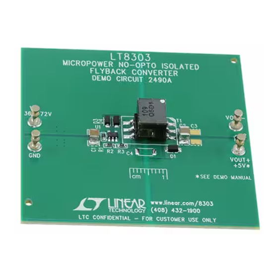
Demonstration circuit 2490A is a micropower no-opto
isolated flyback converter featuring the
demo circuit outputs 5V, and maintains tight regulation
with a load current from 2.5mA to 0.84A over an input
voltage from 36V to 72V. The output current capabil-
ity increases with the input voltage, as shown in the
Performance Summary table.
The DC2490A needs less than 0.5% of its full output
power as a minimum load to maintain good output voltage
regulation. On the DC2490A, in order to avoid preload-
ing, a 5.6V Zener diode is placed between its V
–
V
to serve as a minimum load.
OUT
The Performance Summary table summarizes the perfor-
mance of the demo board at room temperature. The demo
circuit can be easily modified for different applications with
some predesigned transformers.
The LT8303 is a micropower high voltage isolated fly-
back converter. By sampling the isolated output voltage
performance summary
PARAMETER
Input Voltage
Output Voltage
Maximum Output Current
Output Voltage Ripple (Peak to Peak)
Typical Switching Frequency
Efficiency
Arrow.com.
Downloaded from
DEMO MANUAL DC2490A
Isolated Flyback Converter
directly from the primary-side flyback waveform, the part
LT
8303. This
requires no third winding or opto-isolator for regulation.
®
The output voltage is programmed with a single external
resistor. Boundary mode operation provides a small mag-
netic solution with excellent load regulation. Low ripple
Burst Mode
load while minimizing the output voltage ripple. A 0.45A,
150V DMOS power switch is integrated along with all
the high voltage circuitry and control logic into a 5-lead
ThinSOT™ package.
+
and
The LT8303 data sheet gives a complete description of
OUT
the part, operation and application information. The data
sheet must be read in conjunction with this quick start
guide for demo circuit 2490A.
Design files for this circuit board are available at
http://www.linear.com/demo/DC2490A
L, LT, LTC, LTM, Linear Technology, Burst Mode and the Linear logo are registered trademarks
and ThinSOT is a trademark of Linear Technology Corporation. All other trademarks are the
property of their respective owners.
Specifications are at T
CONDITIONS
I
= 2.5mA to 0.65A
OUT
V
= 36V
IN
V
= 48V
IN
V
= 72V
IN
V
= 48V, I
= 0.73A
IN
OUT
V
= 48V, I
= 0.73A
IN
OUT
V
= 36V, I
= 0.65A
IN
OUT
V
= 48V, I
= 0.73A
IN
OUT
V
= 72V, I
= 0.84A
IN
OUT
Micropower No-Opto
operation maintains high efficiency at light
®
= 25°C
A
MIN
TYP
36
48
4.75
5
0.65
0.73
0.84
50
260
86
86
85
LT8303
MAX
UNITS
72
V
5.25
V
A
A
A
mV
kHz
%
%
%
dc2490af
1
Advertisement

Related Manuals for Linear Technology DC2490A


Summary of Contents for Linear Technology DC2490A
- Page 1 The LT8303 is a micropower high voltage isolated fly- L, LT, LTC, LTM, Linear Technology, Burst Mode and the Linear logo are registered trademarks and ThinSOT is a trademark of Linear Technology Corporation. All other trademarks are the back converter. By sampling the isolated output voltage property of their respective owners.
-
Page 2: Quick Start Procedure
DEMO MANUAL DC2490A Quick start proceDure Demonstration circuit 2490A is easy to set up to evalu- 3. Check for the proper output voltages. The output should ate the performance of the LT8303. Refer to Figure 1 for be regulated at 5V (±5%). - Page 3 DEMO MANUAL DC2490A Quick start proceDure Figure 1. Proper Measurement Equipment Setup INPUT OR OUTPUT CAPACITOR Figure 2. Proper Scope Probe Placement for Measuring Input or Output Ripple = 36V = 36V = 48V = 48V = 72V = 72V...
-
Page 4: Parts List
DEMO MANUAL DC2490A parts List ITEM REFERENCE PART DESCRIPTION MANUFACTURER/PART NUMBER Required Circuit Components CAP , 4.7µF, X7S, 100V, 10% 1210 MURATA, GRJ32DC72A475KE11L CAP , 220µF, X5R, 6.3V, 20% 1210 SAMSUNG, CL32A227MQVNNNE DIODE, SCHOTTKY, 30V, 3A, PowerDI123 DIODES INC, SBR3U30P1-7 DIODE, ZENER, 5.6V, 300mW, SOD-523... -
Page 5: Schematic Diagram
Information furnished by Linear Technology Corporation is believed to be accurate and reliable. However, no responsibility is assumed for its use. Linear Technology Corporation makes no representa- tion that the interconnection of its circuits as described herein will not infringe on existing patent rights. - Page 6 Linear Technology Corporation (LTC) provides the enclosed product(s) under the following AS IS conditions: This demonstration board (DEMO BOARD) kit being sold or provided by Linear Technology is intended for use for ENGINEERING DEVELOPMENT OR EVALUATION PURPOSES ONLY and is not provided by LTC for commercial use. As such, the DEMO BOARD herein may not be complete in terms of required design-, marketing-, and/or manufacturing-related protective considerations, including but not limited to product safety measures typically found in finished commercial goods.
Need help?
Do you have a question about the DC2490A and is the answer not in the manual?
Questions and answers