Advertisement
Quick Links
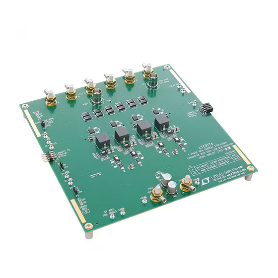
4-Phase High Current Step-Down Converter
Description
Demonstration circuit DC2111A features the
a 4-phase, high output current step-down converter with
sub-mΩ DCR sensing. This high performance converter
operates at a switching frequency of 400kHz over an input
voltage range of 10V to 14V. The 5mm × 5mm DrMOS
and 0.33µH/0.325mΩ inductor provide high efficiency
while supplying 30A per phase. The board comes in two
assembly types. The –A assembly provides a 1.2V/90A
converter with N+1 MOSFET failure protection and the –B
assembly provides a high efficiency 1.2V/120A converter.
1.2V/90A Converter with N+1 MOSFET Failure
Protection
The –A assembly is intended for high reliability applica-
tions which have a very low tolerance for down-time or
which operate in rugged environments. Each phase of the
1.2V/90A converter is protected by its own LTC4226-1
hot swap circuit on the input and an LTC4352 ideal diode
on its output. If an internal DrMOS MOSFET fails, then
that phase will be isolated from the rest of the circuit and
the converter will continue to operate with only a small
perturbation on the output and will provide the full rated
90A load. Once a fault is detected, the PWM signal for that
phase will be floated. This in turn will signal the DrMOS to
pull its TG and BG signals low. Examples of the converter's
response to MOSFET failures can be seen in Figure 2 and
Figure 3. Further protection is provided by a dedicated 5V
bias supply for each phase. If the 5V bias for a given phase
is pulled down due to a DrMOS failure or other fault, the
5V bias for the other phases will not be affected.
In case of an overvoltage event, an external overvoltage
protection circuit will pull down the output. The LTC3774
does have its own crowbar type overvoltage protection,
with Very Low DCR Inductor
LTC
3774
in
but the ideal diodes will prevent the bottom FETs from
®
pulling down the output once an overvoltage is detected.
The external OVP comparator will also provide overvolt-
age protection in case the voltage sense lines are shorted
or reversed.
For a 12V input, the –A assembly provides a full load ef-
ficiency of 89.3% and a peak efficiency of 90.6% which
occurs around 50% load.
1.2V/120A High Efficiency Converter
The –B assembly is a high efficiency 1.2V/120A 4-phase
converter. Given that it does not have the MOSFET failure
protection and redundancy of the –A assembly, it provides
higher efficiency and more output current. For a 12V input
it provides a full load efficiency of 90.6% and a peak ef-
ficiency of 93.1% which occurs at 55% load.
More Features
Both assembly types provide many features. These include:
• Remote sensing
• CLKIN and CLKOUT pins
• PGOOD, RUN and TRACK/SS pins
• Dynamic load circuit
• Optional phase shedding circuit
The LTC3774 data sheet provide a complete description
of the IC operation and application information. The data
sheet must be read in conjunction with the quick start guide.
Design files for this circuit board are available at
http://www.linear.com/demo/DC2111A-A/-B
L, LT, LTC, LTM, Linear Technology and the Linear logo are registered trademarks of Linear
Technology Corporation. All other trademarks are the property of their respective owners.
DEMO MANUAL
DC2111A-A/B
LTC3774EUHE
dc2111aabf
1
Advertisement

Subscribe to Our Youtube Channel
Related Manuals for Linear Technology DC2111A-A/B


Summary of Contents for Linear Technology DC2111A-A/B
- Page 1 The LTC3774 http://www.linear.com/demo/DC2111A-A/-B does have its own crowbar type overvoltage protection, L, LT, LTC, LTM, Linear Technology and the Linear logo are registered trademarks of Linear Technology Corporation. All other trademarks are the property of their respective owners. dc2111aabf...
-
Page 2: Performance Summary
DEMO MANUAL DC2111A-A/-B performance summary Specifications are at T = 25°C Table 1. A Converter (T = 25°C, No Airflow) PARAMETER CONDITION VALUE Minimum Input Voltage Maximum Input Voltage Output Voltage V = 0A to 90A, V = 10V to 14V 1.2V ±... -
Page 3: Quick Start Procedure
DEMO MANUAL DC2111A-A/B Quick start proceDure The evaluation setup for demonstration circuit 2111A is Note 3. For loads less than 5A, some low level noise may shown in Figure 1. To test the board, follow the procedure appear on the output of the –A assembly. This is due to the... - Page 4 DEMO MANUAL DC2111A-A/-B Quick start proceDure – COUT3 – – dc2111aab F01 – SUPPLY Figure 1. Proper Measurement Equipment Setup for DC2111A-A/-B dc2111aabf...
- Page 5 DEMO MANUAL DC2111A-A/B Quick start proceDure (AC) 50mV/DIV 10V/DIV HiZB4 5V/DIV PWM4 5V/DIV VSW1 10V/DIV VSW2 10V/DIV VSW3 10V/DIV VSW4 10V/DIV dc2111aab F02 50µs/DIV Figure 2. 1.2V/90A Converter with N+1 MOSFET Failure Protection. Top MOSFET of Phase 4 Shorted Drain to Source with Full Load on the Output and a 12V Input. The Output Continues to Regulate with Only a small Perturbation on the Output.
- Page 6 DEMO MANUAL DC2111A-A/-B Quick start proceDure (AC) 100mV/DIV LOAD STEP 20A/DIV 50µs/DIV dc2111aab F04 Figure 4. 45A to 90A Load Step Response of the 1.2V/90A Converter with N+1 MOSFET Failure Protection Circuit. V = 12V. (AC) 100mV/DIV 120A LOAD STEP 20A/DIV 50µs/DIV dc2111aab F05...
- Page 7 DEMO MANUAL DC2111A-A/B Quick start proceDure EACH PHASE: DrMOS = FDMF5820DC, BOOST R = 0 L = WURTH 744301033 (0.33µH, 0.32m ) HOT SWAP CIRCUIT: LTC4226-1 WITH FDMS86500DC IDEAL DIODES: LTC4352 WITH BSC010NE2LS DrMOS BIAS = 5.6V BIAS POWER INCLUDED IN EFFICIENCY MEASUREMENT...
- Page 8 DEMO MANUAL DC2111A-A/-B Quick start proceDure V OUT IDEAL DIODES INDUCTORS DrMOS HOT SWAP V IN dc2111aab F08 PHASE 1 PHASE 2 PHASE 3 PHASE 4 Figure 8. Thermal Image of the 1.2V/90A Converter with N+1 MOSFET Failure Protection. Measured with Full Load and an Input Voltage of 12V. T = 21°C.
-
Page 9: Parts List
DEMO MANUAL DC2111A-A/B parts List ITEM REFERENCE PART DESCRIPTION MANUFACTURER/PART NUMBER Required Circuit Components C1, C6, C18, C20, C27, C30, C41, C43, CAP , 2.2µF 10% 16V X5R 0603 MURATA, GRM188R61C225KE15D CAP , 4.7nF, 5%, 25V, X7R 0603 AVX, 06033C472JAT2A C11, C24, C33, C45 CAP , 1µF 20% 25V X5R 0603... - Page 10 RES, 0.007Ω, 1% 1W 2512 VISHAY, WSL25127L000FEA U1, U4, U7, U10 MOSFET, DrMOS DC-DC 2MHz QFN-5X5-31 FAIRCHILD, FDMF5820DC U2, U5, U8, U11 IC, LTC4352CDD DFN12DD LINEAR TECHNOLOGY, LTC4352CDD#PBF U3, U9 IC, LTC3774EUHE UHE-5X6-36P+1 LINEAR TECHNOLOGY, LTC3774EUHE#PBF U6, U12 IC, LTC4226CUD-1 QFN16UD-3X3 LINEAR TECHNOLOGY,LTC4226CUD-1#PBF Bias Supplies CAP , 2.2µF 10% 16V X5R 0603...
- Page 11 INFINEON, BSC010NE2LS TRANSISTOR, NPN, MMBT3904L SOT23 ON SEMI, MMBT3904LT1G R148 RES, 0.1Ω 1% 1W 2512 VISHAY, WSL2512R1000FEA IC, LTC6702IDC DFN8DC LINEAR TECHNOLOGY, LTC6702IDC#PBF Dynamic Load Circuit MOSFET, FDB8832 TO263AB FAIRCHILD, FDB8832 R104 RES, 10k 1% 1/10W 0603 VISHAY, CRCW060310K0FKEA R109 RES, 0.002Ω...
- Page 12 R168, R188, R189, R190, R191 NTC, OPT 0603 / 0805 IC, OPT DFN8DC IC, OPT SOT23-5 IC, LT6703IDC-3 DFN3DC LINEAR TECHNOLOGY, LT6703IDC-3#PBF Hardware: For Demo Board Only E1 TO E12 TESTPOINT, TURRET, 0.095" MILL MAX, 2501-2-00-80-00-00-07-0 HEADER, 3 PIN 0.079 SINGLE ROW WURTH ELEKTRONIK 62000311121 HEADER, 4 PIN 0.079 SINGLE ROW...
-
Page 13: Schematic Diagram
Information furnished by Linear Technology Corporation is believed to be accurate and reliable. However, no responsibility is assumed for its use. Linear Technology Corporation makes no representa- tion that the interconnection of its circuits as described herein will not infringe on existing patent rights. - Page 14 Linear Technology Corporation (LTC) provides the enclosed product(s) under the following AS IS conditions: This demonstration board (DEMO BOARD) kit being sold or provided by Linear Technology is intended for use for ENGINEERING DEVELOPMENT OR EVALUATION PURPOSES ONLY and is not provided by LTC for commercial use. As such, the DEMO BOARD herein may not be complete in terms of required design-, marketing-, and/or manufacturing-related protective considerations, including but not limited to product safety measures typically found in finished commercial goods.
Need help?
Do you have a question about the DC2111A-A/B and is the answer not in the manual?
Questions and answers