Advertisement
Quick Links
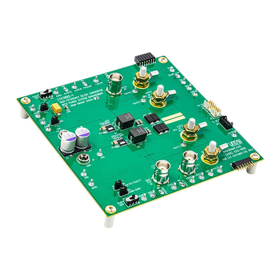
DESCRIPTION
Demonstration circuit 2312A is a high current, high
efficiency, dual phase synchronous buck converter
featuring the LTC3882EUJ-1, a dual output voltage
mode controller with the additional features of dif-
ferential V
sense and dedicated PGOOD output on
OUT
both channels, compared to LTC3882. The LTC3882-1
has the PMBus interface and power system manage-
ment functions.
There are two versions of the boards available:
DC2312A-A: Dual phase dual output configuration. De-
n
fault output setting V
OUT0
DC2312A-B: Dual phase single output configuration.
n
Default output setting V
The DC2312A powers up to default settings and pro-
duces power based on configuration resistors or with
its nonvolatile memory without the need for any serial
bus communication. This allows easy evaluation of the
PERFORMANCE SUMMARY
SYMBOL
PARAMETER
V
Input Supply Range
IN
V
Output Voltage Range (-A Version)
OUT0
I
Output Current Range (-A Version)
OUT0
V
Output Voltage Range (-A Version)
OUT1
I
Output Current Range (-A Version)
OUT1
V
Output Voltage Range (-B Version)
OUT0
I
Output Current Range (-B Version)
OUT0
F
Factory Default Switching (-A Version)
SW
F
Factory Default Switching (-B Version)
SW
EFFICIENCY
Full Load Efficiency (-A Version)
Full Load Efficiency (-B Version)
*Note: The DC2312A uses 2.5V-rated low ESR PosCAP (Part No. 2R5TPE470M7) as output capacitors for optimized load transient performance.
If > 2.0V V
is needed, 4V or 6.3V-rated output capacitors should be used.
OUT
**Note: When continuously running at full load, forced air flow is needed.
with Power System Management
= 1.5V/35A, V
= 1.0V/35A.
OUT1
= 1.0V/70A.
OUT0
Specifications are at T
CONDITIONS
I
= 0A to 35A, V
OUT0
I
= 0A to 35A, V
OUT1
I
= 0A to 70A, V
OUT0
V
= 1.5V, I
OUT0
V
= 1.0V, I
OUT1
V
= 1.0V, I
OUT0
DC2312A-A/DC2312A-B
LTC3882EUJ-1 High Efficiency
Step-Down DC/DC Converter
DC/DC converter. To fully explore the extensive power
system management features of the part, download the
GUI software LTpowerPlay™ onto your PC and use LTC's
2
I
C/SMBus/PMBus Dongle DC1613A to connect to the
board. LTpowerPlay allows the user to reconfigure the
part on-the-fly and store the configuration settings within
its onboard EEPROM, along with viewing telemetry pa-
rameters that include voltage, current, temperature and
fault status.
GUI Software LTpowerPlay Download
The software can be downloaded from:
http://www.linear.com/LTpowerPlay
Design files for this circuit board are available at
http://www.linear.com/demo/DC2312A
L, LT, LTC, LTM, Linear Technology and the Linear logo are registered trademarks and
LTpowerPlay is a trademark of Linear Technology Corporation. All other trademarks are the
property of their respective owners.
= 25°C
A
= 7V to 14V
IN
= 7V to 14V
IN
= 7V to 14V
IN
= 35A, See Figure 5
OUT0
= 35A, See Figure 5
OUT1
= 70A, See Figure 6
OUT0
DEMO MANUAL
MIN
TYP
MAX
7
12
14
0.5
1.5
2.0*
0
35**
0.5
1.0
2.0*
0
35**
0.5
1.0
2.0*
0
70**
500
450
90.6
88.0
87.8
UNITS
V
V
A
V
A
V
A
kHz
kHz
%
%
%
dc2312afb
1
Advertisement

Related Manuals for Linear Technology DC2312A-A


Summary of Contents for Linear Technology DC2312A-A
- Page 1 L, LT, LTC, LTM, Linear Technology and the Linear logo are registered trademarks and bus communication. This allows easy evaluation of the LTpowerPlay is a trademark of Linear Technology Corporation. All other trademarks are the property of their respective owners.
-
Page 2: Quick Start Procedure
– – and from V to V OUT0 OUT1 OUT1 DC2312A-A Version Note. If there is no output, temporarily disconnect the load to make sure that the load is not set too high. JUMPER POSITION FUNCTION Untie GPIO0B to GPIO1B 7. - Page 3 DEMO MANUAL DC2312A-A/DC2312A-B QUICK START PROCEDURE – SHUNT OUT0 OUT0 – OUT0 LOAD – POWER SUPPLY – DC1613A – CONNECTOR – OUT1 LOAD OUT1 OUT1 SHUNT – DC2312A F02 Figure 2. Power Test Setup for DC2312A-A dc2312afb...
- Page 4 DEMO MANUAL DC2312A-A/DC2312A-B QUICK START PROCEDURE – SHUNT OUT0 OUT0_1 – OUT0 LOAD 1 FOR BETTER THERMAL DISTRIBUTION, USE A PIECE OF LOW IMPEDANCE METAL TO CONNECT TOP LAYER V COPPER – AND PULL CURRENT EVENLY FROM J3 TO J4 AND FROM J9 TO J8.
- Page 5 OUT0 = 1.5V OUT0 = 1.0V OUT1 LOAD CURRENT (A) LOAD CURRENT (A) DC2312A F05 DC2312A F06 Figure 5. DC2312A-A, Typical Efficiency Curves, Figure 6. DC2312A-B, Typical Efficiency Curves, = 12V, F = 500kHz, CCM = 12V, F = 450kHz, CCM dc2312afb...
- Page 6 DEMO MANUAL DC2312A-A/DC2312A-B QUICK START PROCEDURE Figure 7. Load Transient Waveform DC2312A-A, V = 12V, V = 1.5V, F = 500kHz, 0% to 25% (8.75A) Load Step OUT0 Figure 8. Load Transient Waveform DC2312A-A, V = 12V, V = 1.0V, F = 500kHz, 0% to 25% (8.75A) Load Step OUT1 Figure 9.
- Page 7 DEMO MANUAL DC2312A-A/DC2312A-B QUICK START PROCEDURE Figure 10. Thermal Picture of DC2312A-A, V = 12V, V = 1.5V/35A, V = 1.0V/35A, f = 500kHz, 400LFM Air Flow OUT0 OUT1 Figure 11. Thermal Picture of DC2312A-B, V = 12V, V = 1.0V/70A, f...
- Page 8 You can use LTpowerPlay to evaluate the software current with the latest set of device drivers Linear Technology ICs by connecting to a demo board and documentation. The LTpowerPlay software can be system. LTpowerPlay can also be used in an offline mode...
- Page 9 1. Download and install the LTPowerPlay GUI: http://www.linear.com/LTpowerPlay 2. Launch the LTpowerPlay GUI. a. The GUI should automatically identify the DC2312A-A. The system tree on the left hand side should look like this: b. A blue message box shows for a few seconds in the...
- Page 10 DEMO MANUAL DC2312A-A/DC2312A-B PARTS LIST DC2312A-A ITEM REFERENCE PART DESCRIPTION MANUFACTURER/PART NUMBER Required Circuit Components C5, C52, C53 CAP., X7R, 0.1µF, 16V, 10%, 0402 AVX, 0402YC104KAT2A CF, COUT4, COUT5 CAP., X7R, 0.1uF, 16V, 10%, 0603 AVX, 0603YC104KAT2A CFFW1, CFFW2 CAP., NP0, 22pF, 25V, 10%, 0402...
- Page 11 DEMO MANUAL DC2312A-A/DC2312A-B PARTS LIST DC2312A-A ITEM REFERENCE PART DESCRIPTION MANUFACTURER/PART NUMBER Additional Demo Board Circuit Components D4, D7 (OPT) OPTIONAL C20, C42 CAP., X5R, 0.22µF, 16V, 10%, 0402 TDK, C1005X5R1C224K CAP., X7R, 220pF, 50V, 10%, 0402 MURATA, GRM155R71H221KA01D C29, C44 CAP., X7R, 0.01µF, 16V, 10%, 0603...
- Page 12 DEMO MANUAL DC2312A-A/DC2312A-B PARTS LIST DC2312A-A ITEM REFERENCE PART DESCRIPTION MANUFACTURER/PART NUMBER Hardware – For Demo Board Only E1-E4, E7-E19, E21-E31 TESTPOINT, TURRET, .094" MILL-MAX, 2501-2-00-80-00-00-07-0 J1, J2 BANANA SMALL KEYSTONE, 575-4 J3, J4, J8, J9 STUD, TESTPIN PEM, KFH-032-10...
- Page 13 DEMO MANUAL DC2312A-A/DC2312A-B PARTS LIST DC2312A-B ITEM REFERENCE PART DESCRIPTION MANUFACTURER/PART NUMBER Required Circuit Components C5, C52, C53 CAP., X7R, 0.1µF, 16V, 10%, 0402 AVX, 0402YC104KAT2A CF, COUT4, COUT5 CAP., X7R, 0.1µF, 16V, 10%, 0603 AVX, 0603YC104KAT2A CFFW1, CFFW2 CAP., NP0, 22pF, 25V, 10%, 0402...
- Page 14 DEMO MANUAL DC2312A-A/DC2312A-B PARTS LIST DC2312A-B ITEM REFERENCE PART DESCRIPTION MANUFACTURER/PART NUMBER Additional Demo Board Circuit Components D4, D7 (OPT) OPTIONAL C20, C42 CAP., X5R, 0.22µF, 16V, 10%, 0402 TDK, C1005X5R1C224K CAP., X7R, 220pF, 50V, 10%, 0402 MURATA, GRM155R71H221KA01D C29, C44 CAP., X7R, 0.01µF, 16V, 10%, 0603...
- Page 15 DEMO MANUAL DC2312A-A/DC2312A-B PARTS LIST DC2312A-B ITEM REFERENCE PART DESCRIPTION MANUFACTURER/PART NUMBER Hardware – For Demo Board Only E1-E4, E7-E19, E21-E31 TESTPOINT, TURRET, .094" MILL-MAX, 2501-2-00-80-00-00-07-0 J1, J2 BANANA SMALL KEYSTONE, 575-4 J3, J4, J8, J9 STUD, TEST PIN PEM, KFH-032-10...
- Page 16 DEMO MANUAL DC2312A-A/DC2312A-B SCHEMATIC DIAGRAM DC2312A-A dc2312afb...
- Page 17 DEMO MANUAL DC2312A-A/DC2312A-B SCHEMATIC DIAGRAM DC2312A-A dc2312afb...
- Page 18 DEMO MANUAL DC2312A-A/DC2312A-B SCHEMATIC DIAGRAM DC2312A-A dc2312afb...
- Page 19 DEMO MANUAL DC2312A-A/DC2312A-B SCHEMATIC DIAGRAM DC2312A-B dc2312afb...
- Page 20 DEMO MANUAL DC2312A-A/DC2312A-B SCHEMATIC DIAGRAM DC2312A-B dc2312afb...
- Page 21 Information furnished by Linear Technology Corporation is believed to be accurate and reliable. However, no responsibility is assumed for its use. Linear Technology Corporation makes no representa- tion that the interconnection of its circuits as described herein will not infringe on existing patent rights.
- Page 22 Linear Technology Corporation (LTC) provides the enclosed product(s) under the following AS IS conditions: This demonstration board (DEMO BOARD) kit being sold or provided by Linear Technology is intended for use for ENGINEERING DEVELOPMENT OR EVALUATION PURPOSES ONLY and is not provided by LTC for commercial use. As such, the DEMO BOARD herein may not be complete in terms of required design-, marketing-, and/or manufacturing-related protective considerations, including but not limited to product safety measures typically found in finished commercial goods.
Need help?
Do you have a question about the DC2312A-A and is the answer not in the manual?
Questions and answers