Table of Contents
Advertisement
ASCON spa
ISO 9001
C e r t i f i e d
ASCON spa
20021 Bollate
(Milan) Italy
via Falzarego, 9/11
Tel. +39 02 333 371
Fax +39 02 350 4243
http://www.ascon.it
e-mail info@ascon.it
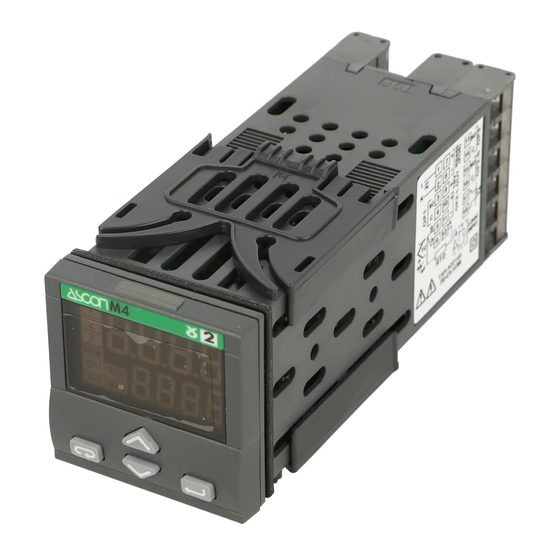
Temperature Controller
with Limit Switch
function
1
/
DIN - 48 x 48
16
M4 line
U s e r m a n u a l • M . I . U . M 4 L - 1 / 0 3 . 1 0 • C o d . J 3 0 - 4 7 8 - 1 A M 4 L I E
c
c
C
US
U L
LISTED
Advertisement
Table of Contents

Related Manuals for ascon M4 series


Summary of Contents for ascon M4 series
- Page 1 M4 line ASCON spa U s e r m a n u a l • M . I . U . M 4 L - 1 / 0 3 . 1 0 • C o d . J 3 0 - 4 7 8 - 1 A M 4 L I E...
- Page 2 Temperature Controller with Limit Switch Function DIN - 48 x 48 M4 line LISTED 274. 8 275. 0...
- Page 3 Information Please, read carefully these instructions before proceeding with the installation of the controller. Class II instrument, for indoor use only. OTES ON ELECTRIC This controller has been designed with compliance to: Regulations on electrical apparatus (appliance, systems and installa- SAFETY AND tions) according to the European Community directive 73/23/EEC amend- ELECTROMAGNETIC...
- Page 4 Table of contents ABLE OF ONTENTS Page NSTALLATION ..........................Page LECTRICAL CONNECTIONS ..................Page RODUCT CODING ........................ Page PERATIONS ..........................Page IMIT SWITCH FUNCTIONS ................... Page ECHNICAL SPECIFICATIONS ..................Operating mode Resources Limit Switch Supervisory Switch Main universal input Digital input (option) Digital Input connected functions Modbus RS485 LIMIT...
-
Page 5: Installation
1 - Installation INSTALLATION 1.1 GENERAL DESCRIPTION IP 20 Terminal Block EN61010 - 1 (IEC1010 - 1) Installation must only be carried out by qualified personnel. Before proceeding with the instal- Panel surface lation of this controller, follow the instructions illustrated in this man- ual and, particularly the installation precautions marked with the symbol, related to the European... - Page 6 1 - Installation 1.2 DIMENSIONAL DETAILS 1.2.1 PANEL MOUNTING MODELS Instrument dimensions Panel cut-out mm min. 2.56 in min. 1.89 1.89 mm max. 0.79 in max. 45 +0.6 1.78 +0.023 in 4.72...
- Page 7 1 - Installation 1.2.2 DIN RAIL MOUNTING MODELS Instrument dimensions 78.5 mm max. in max. 87.5 mm max. in max. mm max. in max.
-
Page 8: Environmental Ratings
1 - Installation 1.4 ENVIRONMENTAL RATINGS Operating conditions Altitude up to 2000 m Temperature 0… 55°C Relative humidity 5… 95 % non-condensing Special conditions Suggestions Altitude > 2000 m Use 24V supply version Temperature >55°C Use forced air ventilation Humidity > 95% Warm up Conducting atmosphere Use filter... - Page 9 1 - Installation 1.5 INSTRUMENT MOUNTING 1.5.1 PANEL MOUNTING MODELS [1] Instrument insertion Installing the locking clamps Clamps removing 1 Prepare panel cut-out; 1 Fit the mounting clamps; 1 Insert the screwdriver in the clips 2 Check front panel gasket posi- 2 Push the mounting clamps of the clamps;...
- Page 10 1 - Installation 1.5.2 DIN RAIL MOUNTING MODELS 1.5.4 INSTRUMENT UNPLUGGING The instructions that follow are Instrument installation Instrument removal valid for both the panel and DIN rail 1 Hook the “A” portion of the instru- 1 Press the lower part of the DIN rail mounting models.
-
Page 11: Terminal Block
2 - Electrical connections ELECTRICAL 2.1 TERMINAL BLOCK [1] CONNECTIONS Rear terminal cover 5.7 mm 0.22 in Cable size 1 mm (18 AWG) 18 screw terminals Terminals Pin connector Option terminals q 1.4 mm 0.055 in max. Tightening torque 0.5 Nm Fork-shape Positive screw AMP 165004... - Page 12 2 - Electrical connections PRECAUTIONS 2.2 SUGGESTED WIRES ROUTING Despite the fact that the instrument Conduit for supply and output cables has been designed to work in an harsh and noisy environmental (level IV of the industrial standard IEC 801-4), it is recommended to follow the following suggestions.
-
Page 13: Example Of Wiring Diagram
2 - Electrical connections 2.3 EXAMPLE OF WIRING DIAGRAM Power supply Supervisor 2.3.1 POWER SUPPLY Power supply Switching power supply with mul- switch RS485 RX/TX tiple isolation and PTC protection. PTC [4] • Standard version: nominal voltage: 100... 240V (-15%/+10%); Fuse Fuse frequency:... -
Page 14: Digital Input
2 - Electrical connections 2.3.2 PV CONTROL INPUT A For L-J-K-S-T thermocouple type D For mA, mV • Connect the wires with the mV mA polarity as shown. • Use always compensation cable of the correct type for the ther- mocouple used. -
Page 15: Serial Communications
2 - Electrical connections Single relay output 2.3.3 OP1 - OP2 OUTPUTS LIMIT SWITCH RELAY • NO contact for resistive load OUTPUT (OP1) of up to 2A/250V max. or Single relay output OP2 output can be Relay (Std) or T at 120 V •... -
Page 16: P Roduct Coding
3 - Product coding PRODUCT CODING The complete code is shown on the instrument label. The informa- Instrument Label tions about product coding are 3190 accessible from the front panel by means of a particular procedure described at section 4.2.2 page 21 Hard : M4-3190-9000 CONF... -
Page 17: Model Code
3 - Product coding 3.1 MODEL CODE The product code indicates the specific hardware configuration of the instrument, that can be modified, by specialized engineers only. Line Basic Accessories Model: A 1 C 0 9 F G H Line Notes: 1] Standard shunt resistor without Power supply 100 - 240V... -
Page 18: Configuration Coding
3 - Product coding CONFIGURATION CODING Input type and range TR Pt100 IEC751 -99.9…300.0 °C -99.9…572.0 °F The configuration code consists of TR Pt100 IEC751 -200…600 °C -328…1112 °F 8 digits that identify the operat- TC L Fe-Const DIN43710 0…600 °C 32…1112 °F ing characteristics of the controller, TC J Fe-Cu45% Ni IEC584... - Page 19 3 - Product coding Alarm 2 (AL2) type and function Not active If, when the controller is powered ON for the first time, the display Sensor break alarm shows the following message: Active high Absolute Active low Active high Deviation 9999 Active low Active out...
-
Page 20: O Perations
4 - Operations OPERATIONS OPERATOR PANEL 4.1.1 KEYS FUNCTIONS AND DISPLAY IN OPERATOR MODE When the measured When the measured IN input value Limit & value is greater than value is less than the in engineering Supervisory sensor high range sensor low range units threshold... -
Page 21: Operator Interface
4 - Operations 4.1.3 OPERATOR INTERFACE During normal operation the Any operator operation other instrument is in Operator Mode: than limiter AL1 acknowledge the upper display shows the (è key) or auxiliary AL2 Process Value (IN) in engineering acknowledge (Y key) when the units and the lower display AL2 is configured, is protected shows the current setting for AL1... - Page 22 4 - Operations DISPLAY When the display operation is select- 4.2.1 PROCESS DATA DISPLAY ed, the controller presents auto- matically all the most important parameters and configuration infor- 274. 8 275. 0 mation. Operator mode AL1 Threshold 275. . 0 A1s.
- Page 23 4 - Operations 4.2.2 CONFIGURATION CODES DISPLAY When necessary, the operator can 274. 8 0200 view the instrument main data (no Operator Configuration 275. 0 Con2 changes are possible with the pre- mode code 2 part (see page 18) sent procedure). 274.
- Page 24 4 - Operations 4.3 PARAMETER SETTING 4.3.1 NUMERIC ENTRY (e.g. the modification of the AL1 threshold from 275.0 to 240.0) Press S or G momentarily to é change the value of 1 unit each time 274. 8 Operator mode 275. 0 Value the key is pressed.
- Page 25 4 - Operations 4.3.2 MNEMONIC CODES SETTING (e.g. configuration see page 30) Engineering Units Pressing istantaneously the $ or % key, the system shows the °f °C next or the previous mnemonic code of the selected parameter. Degrees Degrees Unit Unit Centigrade Fahrenheit...
- Page 26 4 - Operations 4.4 PARAMETERISATION Parameter Parameter The parameter setting procedure value mnemonic has a timeout. If no keys are code pressed for, at least, 30 seconds, 275. 0 the controller switches back, auto- matically, to the operator mode. A1S. P After having selected the parame- ter or the code, press $ and % to display or modify the value (see...
- Page 27 4 - Operations 274. 8 Password pAss Operator mode entry 275. 0 Code entry 0000... 9999 Must be equal to the value of the parameter Code (factory default 33) Notes [1] Not presented if the controller has been configured as: AL2 not active or sen- sor break (configuration code P = 0 or 1) [2] When the AL2 alarm is configured as “Sensor Break”...
- Page 28 4 - Operations PARAMETER MENU é é Limit switch Supervisory switch A1s. p A2S. P threshold threshold [1] (see page 28) (see page 28) é 0. 5 é Input shift A1hy AL1 hysteresis In. s h /-60... +60 digits 0.1… 10.0% of span é...
- Page 29 4 - Operations PT100 PARAMETERS Band alarm - AL2 AL2 threshold Wire A open Over-range Active Wires A and B Over-range AL1 Limit Switch # A 1s. p in short circuit, for a while, then threshold wire b open under-range Active All other conditions Under-range...
- Page 30 4 - Operations # b loc ALARM_2 AL1 limit switch Input shift # I n. s h # A 1hy START-UP DISABLING hysteresis Ramp down (e.g.: AL2 Abs. high) This value is added to the measured AL2 supervisory # A 2hy input value (IN).
- Page 31 4 - Operations 4.6 CONFIGURATION pAss Password entry 274. 8 The configuration of the controller Operator mode 275. . 0 is specified through a 8 digit code Code entry that defines the type of input and 0... 9999 Must be equal to the alarms.
- Page 32 4 - Operations CONFIGURATION MENU [1] Table of the supported Engineering Units. Direct access to the configuration °C Centigrade degrees * A From parameterisation (see page 28). °f Fahrenheit degrees * B At the first power on when the none none controller is not configured: 9999...
-
Page 33: L Imit Switch Functions
5 - Limit Switch Function LIMIT SWITCH LIMIT SWITCH FUNCTION (ALARM_1) FUNCTION The limiter can operate as a high limit), the OP1 relay will remain limiter or low limiter. Only output de-energized with the contact relay OP1 can be used as limit open until the operator manually In order to have the limit switch switch. - Page 34 5 - Limit Switch Function The complete operation mode is detailed in the table that follows: Limiter status OP1 contact Led 1 Limiter can change status by: Non alarm status Energized Input conditions (contact closed) Normal operation AL1 condition Stays in non Transition to alarm status non-acknowledged...
- Page 35 5 - Limit Switch Function The limiter has a Status Retention capability, it only applies to the Limiter AL1 and OP1 output status. If the limiter is configured for the Status Retention and the power is switched ON, the limiter will operate as detailed in the table that follows: Limiter Status at previous Input AL1 condition at new...
- Page 36 5 - Limit Switch Function 5.2 SUPERVISORY SWITCH (AL2) The OP2 relay output contact is used as a normal auxiliary alarm (AL2). AL2 operation is configurable and independent from the operation of the limiter output OP1. Configuration allows an operator to choose the alarm type, OP2 action, automatic reset/latching.
- Page 37 5 - Limit Switch Function AL2 Reset = Man AL2L.b = None or Blocking Status Status transition contact Input Operator acknowledgment Description Non alarm Alarm condition condition Non alarm No transition Transition to 1 Alarm Transition to 0 No transition No transition Transition to 2 Silence...
-
Page 38: Technical Specifications
6 - Technical Specifications TECHNICAL SPECIFICATIONS Features Description (at 25°C environmental temp.) A/D converter resolution: 50,000 points Update measurement time: 0.2 seconds Common Sampling time: 0.5 seconds characteristics Input bias: -60… +60 digit Input filter with enable/disable: 1… 30 seconds 0.25% ±1 digit for temperature sensors 0.1% ±1 digits for mV Between 100…... - Page 39 8 - Technical specifications Features Description (at 25°C environmental temp.) Digital input The closure of the external contact produces the acknowledgment of AL1 (if the function is enabled) (option) SPST Relay N.O.: 2A/250V for resistive load; OP1 output 4A/120V for resistive load SPST Relay N.O.: 2A/250V for resistive load;...
-
Page 40: Warranty
Warranty WARRANTY We warrant that the prod- ucts will be free from defects in material and workmanship for 3 years from the date of delivery. The warranty above shall not apply for any failure caused by the use of the product not in line with the instructions reported on this manual. - Page 41 ASCON’S WORLDWIDE SALES NETWORK SUBSIDIARY GERMANY RANCH FFICE GMBH Phone +34 93 311 98 11 NDUSTRIE LEKTRONIK FRANCE Phone +49 2365 915 220 +34 93 311 93 65 ASCON F +49 2365 915 225 Phone +34 91 656 04 71...
Need help?
Do you have a question about the M4 series and is the answer not in the manual?
Questions and answers