
Related Manuals for ascon XE Series


Summary of Contents for ascon XE Series
- Page 1 Configurable Multi-input with time-proportioning output Series INSTRUCTION MANUAL MIU.XE-6/96.12/E COD. J30-154-1AXE- ING ASCON spa...
-
Page 2: Table Of Contents
GENERAL INDEX IDENTIFICATION OF MODEL ........page 1 FUNCTION OF KEYS AND DISPLAYS ......page 3 DIMENSIONS, INSTALLATION ........page 6 ELECTRICAL WIRING ........... page 8 Y2 - Y3 AUXILIARY OUTPUTS ........page 14 PASSWORDS ..............page 17 PROGRAMMING PROCEDURE (see enclosed leaflet) CONFIGURATION PARAMETERS OPERATING DIRECTIONS (see enclosed leaflet) -
Page 3: Identification Of Model
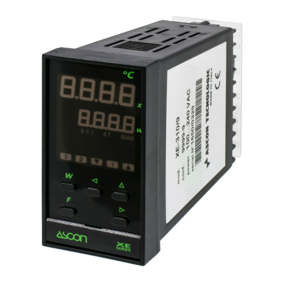
1 • IDENTIFICATION OF MODEL Thank you for choosing an ASCON controller The instruments of the XE series belong to the last generation of microprocessor based controller, are universal, very powerful but simple to use. They are fitted with AUTO-TUNE, as aid for system start-up, and serial communication for introduction into a distributed control network. - Page 4 1 • IDENTIFICATION OF MODEL 1.2 Configuration code Configuration code Beginning and end of scale Model code Input X Main output Y1 239. 5 239. 5 Auxiliary output Y2 Auxiliary output Y3 Beginning and end of scale (for mA and Volt input only) The controller is normally configured in the factory.
-
Page 5: Function Of Keys And Displays
2 • FUNCTION OF KEYS AND DISPLAYS 239. 5 Process variable "X" Set point W Auto-tune in 239. 5 course Auxiliary Active serial output communication Y2 “ON” Auxiliary output Y1F (Cool)“ON” Auxiliary output Main output Y3 “ON” Y1"ON" Main output Y1 Functions (heat) "ON"... - Page 6 2 • FUNCTION OF KEYS AND DISPLAYS NUMERIC INDICATORS X, W 1 -Process The value of measure X is expressed in engineering Variable (X) (green) units. 8888 ____ If above end of scale 8888 ---- 239. 5 If below beginning of scale •...
- Page 7 2 • FUNCTION OF KEYS AND DISPLAYS LEDS FOR OPERATING STATE 6 - Auto-Tune (green) Lit when Auto-Tune or Expert-Tune is in course 7 - Serial comm. (green) Permanently lit when the serial communication is enabled to write. Flashes with signal in transit 239.
-
Page 8: Dimensions, Installation
3 • DIMENSIONS - INSTALLATION 3.1 - Overall dimensions (in compliance with DIN 43700) Ring with hook and Front cover locking screw projection 60 min. 65 min. with Wiring protetection protection IP65 plate 110 min. Advised 150 min. thickness with 1 ÷... - Page 9 3 • DIMENSIONS - INSTALLATION 3.2 - Panel installation A • Panel fitting B • Fixing with ring Install away from: Knurl for hook • heat sources hold • corrosive gases • dusty environments Holding hooks Locking AMBIENT Seal ring fitting screws Temperature: 0 ÷...
-
Page 10: Electrical Wiring
4 • ELECTRICAL WIRING A • Terminal board B • Freeing the terminals 28 screw terminals M3.5 Lift the plate to free Plate pin the pin Wiring protection plate Rotate downwards Plate screw 3 gilded Cold joint terminals for compensation input signals thermometer C •... - Page 11 4 • ELECTRICAL WIRING Although this controller is designed to resist the heaviest disturbances present in industrial environments (level IV of standard (IEC 801-4), it is advised to keep to the following precautions: Precautions Single out supply line from power line Keep away from teleruptors, electromagnetic contactors and powerful motors Keep away from power groups, in particular if with phase...
- Page 12 4 • ELECTRICAL WIRING Wiring diagram Single power supply 100…240 Vac - 50/60 Hz Serial communication (optional) Relay Auxiliary output + 24 Vdc (2) 4…20 mA Relay Main output Relay Auxiliary output 2-wire channel cool) transmitter Input process Main output variable (X) Logic 0/15 Vdc J, L,...
- Page 13 4 • ELECTRICAL WIRING 2 • Process Variable (X) A - For thermocouples J-L-K-S-R • Respect polarities • For eventual extensions, use a compensated cable suitable for the type of thermocouple used • The eventual shield must be well earthed Line: max.
- Page 14 4 • ELECTRICAL WIRING 3 • Main output Y1 A • Relay Single Action NO contact, capacity 3A/250Vac Load Load for resistive loads (transition 2 x 10 min. at 3A/250Vac) B • Logic Single Action Output 0/15Vdc Load (20mA max.) galvanically isolated Relay or static contactor 4 •...
- Page 15 4 • ELECTRICAL WIRING 6 • Serial communication (option) Interface 20mA C.L. passive and galvanically isolated Transmission Consult Directions for use “SERIAL COMMUNICATION SUPPLEMENT Zener Reception MIU.-CS/E” 2,7 V supplied separately. Note Zener 2,7 V Only for 20mA C.L.
-
Page 16: Y2 - Y3 Auxiliary Outputs
5 • Y2 - Y3 AUXILIARY OUTPUTS Deviation Set point ∆W (1) Active high (above) -0...300 units compared to W1 Active low (under) ∆W -300 units +300 units Band Set point I∆WI (1) Active Out -0...300 units (above) compared to W1 Active In (under) I∆WI... - Page 17 5 • Y2 - Y3 AUXILIARY OUTPUTS Deviation with startup inhibition inhibition ∆W Set point ∆W (1) Active high (above) -300...+300 units Startup compared to W1 Active low ∆W (below) inhibition Startup “Loop-Break-Alarm” LBA (control loop defect/interruption) Any interruption in the connections or 239.
- Page 18 5 • Y2 - Y3 AUXILIARY OUTPUTS Double time programmable intervention (Heat - Cool) (Y3) Only for models with option Y3 is Cool Heat 100% 100% possible to have a double action Y1F limit Y1F limit regulation (for instance Heat - Cool). Y 1 F Y 1 C (0…-100%)
-
Page 19: Passwords
6 • PASSWORDS In order to prevent tampering or inadvertent alterations of the configuration or of some important parameters at the programming stage, 2 passwords have to be entered. 3333 6.1 Password of access to configuration Enter password of access to configuration W p Ass 3333 (see enclosed leaflet) -
Page 20: Set Point
10 • TECHNICAL DATA 0.2% ± 1 digit (for input with RTD Pt100 and thermocouples) Accuracy (a25°C amb.) 0.1% ± 1 digit (for input in current and voltage) RTD Pt100 Pt100 (IEC 751) Thermocouples J-K-S-R (IEC 584), L (DIN 43710) Process Variable "X"... - Page 21 10 • TECHNICAL DATA Relay 2 contacts NO, 3A/250Vac, 2x10 transitions active high (above the set point) Action mode active low (below the set point) Hysteresis 0,1..10% Auxiliary ± 300 digit (with or without deviation outputs inhibited startup) Y2 - Y3 Type of Set point band 0..300 digit...
- Page 22 Faults caused by use other than that described in these operating instructions are excluded from the guarantee. ASCON spa 20021 Bollate (Milano), Italy Via Falzarego, 9/11 - Tel. (0039 - 2) 33337.1 Fax (0039 - 2) 3504243 - Telex 322451 ASCON I...
Need help?
Do you have a question about the XE Series and is the answer not in the manual?
Questions and answers