Table of Contents
Advertisement
ASCON spa
ISO 9001
C e r t i f i e d
ASCON spa
20021 Bollate
(Milano) Italy
via Falzarego, 9/11
Tel. +39 02 333 371
Fax +39 02 350 4243
http://www.ascon.it
e-mail sales@ascon.it
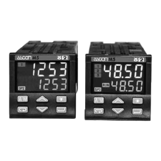
Process Controller
with Setpoint
Programmer
1
/
DIN - 48 x 48
16
M5 line
U s e r M a n u a l • M . I . U . M 5 - 4 / 0 3 . 0 1 • C o d . J 3 0 - 4 7 8 - 1 A M 5 I E
c
c
C
US
U L
LISTED
Advertisement
Table of Contents

Related Manuals for ascon M5 Series


Summarization of Contents
Indications
NOTES ON ELECTRIC SAFETY AND ELECTROMAGNETIC COMPATIBILITY
General safety and EMC compliance information for the controller.
1 INTRODUCTION
POWERFUL FEATURES AND A WIDE RANGE OF FUNCTIONALITIES
Overview of the M5 line controllers and their capabilities.
1.1 PRODUCT CODING
Details on how to interpret the product code for the instrument.
2 INSTALLATION
2.1 INSTALLATION DESCRIPTION
Details on the physical installation and components of the controller.
2.2 ENVIRONMENTAL RATINGS
Operating conditions and environmental limits for the controller.
2.3 PANEL MOUNTING [1]
Instructions and guidelines for mounting the controller into a panel.
3 ELECTRICAL CONNECTIONS
3.1 TERMINATION UNIT [1]
Information on terminal connections and wiring.
3.2 RECOMMENDED ROUTING OF WIRES
Guidance on proper wiring practices to avoid interference.
3.3 TYPICAL INSTRUMENT WIRING (valve control)
Example wiring diagram for a specific application.
4 OPERATION
4.1.A KEYS FUNCTION AND DISPLAY IN OPERATOR MODE
Explanation of controller buttons and display in operator mode.
4.1.B KEYS FUNCTION AND DISPLAY IN PROGRAMMING MODE
Explanation of controller buttons and display in programming mode.
4.2 CONFIGURATION PROCEDURE
Step-by-step guide for configuring controller settings.
4.2.1 AL1, AL2, AL3, AL4 ALARMS CONFIGURATION
Configuration of the four available alarm functions.
4.3 PARAMETER SETTING
Detailed guide on setting various operational parameters.
4.4 ACCESS LEVEL - PASSWORD - CALIBRATION
Managing user access levels and password protection.
5 DISPLAYS
5.1 STANDARD DISPLAY
Overview of the standard display modes and information shown.
5.2 FAST VIEW
Procedure for quick access and modification of common parameters.
6 COMMANDS
6.1 KEYBOARD
Commands that can be entered using the controller's keypad.
6.2 DIGITAL INPUT COMMANDS
Functions activated via digital inputs on the controller.
7 PROGRAMMED SETPOINT
7.1 PROGRAM STRUCTURE
Description of the program structure and segments.
7.2 SETPOINT PROGRAMMER OPERATION
How the setpoint programmer operates, including restart after power failure.
7.3 CREATION AND MODIFICATION OF A PROG.
Guide to creating and modifying setpoint programs.
7.4 START/STOP OF A PROGRAM
Commands for starting, stopping, and holding programmed setpoints.
8 TECHNICAL SPECIFICATIONS
Operating modes
Details on different operating modes and algorithms.
PV input
Specifications related to the process variable input.
Control output
Specifications for the controller's output signals.
General characteristics
General electrical, safety, and dimensional specifications.
Need help?
Do you have a question about the M5 Series and is the answer not in the manual?
Questions and answers