Advertisement
Quick Links
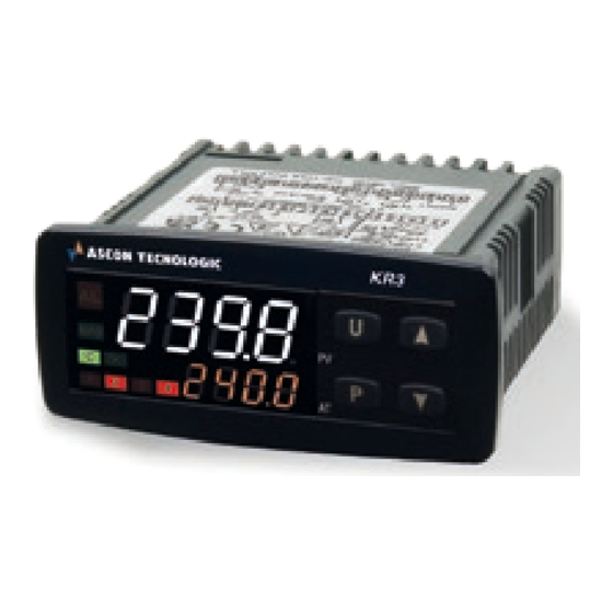
KR_
CONTROLLER AND
MINI-PROGRAMMER
Engineering Manual
23/03 - Code: ISTR_M_KR-SERIES_E_11_--
ASCON TECNOLOGIC S.r.l. a socio unico
Viale Indipendenza, 56 - 27029 VIGEVANO (PV) ITALY
Tel.: +39 0381 69871 - Fax: +39 0381 698730
Web site: http:\\www.ascontecnologic.com
e-mail: info@ascontecnologic.com
1 OUTLINE DIMENSIONS (mm)
1.1
Mounting requirements
This instrument is intended for permanent installation, for in-
door use only, in an electrical panel which encloses the rear
housing, exposed terminals and wiring on the back.
Select a mounting location having the following characteris-
tics:
1.
It should be easily accessible;
2.
There is minimum vibrations and no impact;
3.
There are no corrosive gases;
4.
There are no water or other fluids (i.e. condensation);
5.
The ambient temperature is in accordance with the
operative temperature (0... 50°C);
6.
The relative humidity is in accordance with the instru-
ment specifications (20... 85%);
The instrument can be mounted on panel with a maximum
thickness of 15 mm.
When the maximum front protection (IP65) is desired, the
optional screw type bracket must be used (see "4. How to
order" paragraph for details).
1.2
Dimensions
Instrument with removable terminals
78
PV
AT
6
64
Ascon Tecnologic - KR-Series - ENGINEERING MANUAL - PAG. 1
Screw removable terminals
60
1.3
Panel cutout
+0.6
71
2 CONNECTION DIAGRAM
Passive TX,
2 wires,
4... 20 mA
0/12... 60 mV,
0/1... 5V,
+
0/2... 10V
4... 20 mA
+
(active)
Pt1000
Pt100
+
TC
Power
Supply
Note: Terminal 4 can be programmed as:
- Digital Input (DI2) contacts connected to terminals 4 -11;
-
0... 12 V SSR Drive Output (Out4) the load connected between
terminals 4 - 11;
- 12 Vdc (20 mA) power supply for the 2/3 wire transmitters (Out4).
2.1
General notes about wiring
1.
Do not run input wires together with power cables.
2.
External components (like zener barriers, etc.) con-
nected between sensor and input terminals may cause
errors in measurement due to excessive and/or not bal-
anced line resistance or possible leakage currents.
23.5
14.5
3.
When a shielded cable is used, the protection shield
should be connected to ground at one side only.
4.
Pay attention to the line resistance, a high line resist-
ance may cause measurement errors.
Spring removable terminals
60
15.5
8.3
18.85
86 mm min.
mm
Relay Out 1:
4 (4) A/250 VAC
Relay Out 2, 3:
2 (1) A/250 VAC (*)
SSR Out 1, 2 , 3: 10 VDC/15 mA
Out1:
4... 20 mA (KR3 only)
SSR Out4:
12 VDC/20 mA
* KR3 servodrive models: both Out2 and Out3
are to be selected as "M" in Configuration code;
Out2: open, Out3: close
DI2
DI1
+ -
Note
Out4
Out3
Out2
C
NO
C
NO
15
8.3
26
RS485
D-
D+
Out1
C
NC
NO
Advertisement

Subscribe to Our Youtube Channel
Related Manuals for ascon KR Series


Summary of Contents for ascon KR Series
- Page 1 When a shielded cable is used, the protection shield should be connected to ground at one side only. Pay attention to the line resistance, a high line resist- ance may cause measurement errors. Ascon Tecnologic - KR-Series - ENGINEERING MANUAL - PAG. 1...
- Page 2 Line resistance: Automatic compensation up to 20W/wire 0/4...20 mA with maximum error 0.3°C. passive Calibration: According to EN 60751/A2. transmitter Note: The resistance of the 3 wires must be the same. External power supply Ascon Tecnologic - KR-Series - ENGINEERING MANUAL - PAG. 2...
- Page 3 V output: 0/2... 10 V, galvanically isolated, RL min.: 500W. 2.3.2 Output 2 (Out2) Relay Output Out1 contact rating: - 2 A /250 V cosj = 1 - 1 A /250 V cosj = 0.4 Operation: 1 x 10 Ascon Tecnologic - KR-Series - ENGINEERING MANUAL - PAG. 3...
- Page 4 (Out 4 Overload) indication. SSR Output Logic level 0: Vout < 0.5 VDC; Logic level 1: 12 V ± 20%, 20 mA max.. Note: Overload protected. Ascon Tecnologic - KR-Series - ENGINEERING MANUAL - PAG. 4...
- Page 5 Pollution category: 2. V = AT package + Screw type bracket for IP65 Note: For servomotor drive, both Output 2 and Output 3 codes must be selected as “M”. Ascon Tecnologic - KR-Series - ENGINEERING MANUAL - PAG. 5...
- Page 6 • The set point value alternate with the message St. b Y; – In all cases, the decimal figure of the less significant digit of the lower display is lit. We define all the above described conditions as “Standard Display”. Ascon Tecnologic - KR-Series - ENGINEERING MANUAL - PAG. 6...
- Page 7 2. To select the PID control mode for servodrive (N plus O = 20 or 21), in the order code both Output 2 and Output 3 codes must be selected as “M” (see “How to order” pargraph). Ascon Tecnologic - KR-Series - ENGINEERING MANUAL - PAG. 7...
- Page 8 • When the code of the input type is equal to e (see “How to order” paragraph). TC J (-50... +1000°C/-58... +1832°F); crAL TC K (-50... +1370°C/-58... +2498°F); TC S (-50... +1760°C/-58... +3200°F); TC R (-50... +1760°C/-58... +3200); Ascon Tecnologic - KR-Series - ENGINEERING MANUAL - PAG. 8...
- Page 9 The instrument does not rescale the temperature 5 Manual mode; values inserted by the user (thresholds, limits etc.). 6 HEAt with SP1 and CooL with “SP2” [status] (see “Note about digital inputs”); Ascon Tecnologic - KR-Series - ENGINEERING MANUAL - PAG. 9...
- Page 10 2 DI1 Direct action, reset timer count; DI2 (if configured) Reverse action; 10 Timer run/hold [Status]: 3 DI1 Reverse action, - Contact close = timer RUN; DI2 (if configured) Reverse action. Ascon Tecnologic - KR-Series - ENGINEERING MANUAL - PAG. 10...
- Page 11 Range: -1999 to [16] Ao1H. St.By Stand By status indicator; diF1 Repeats the digital input 1 status; diF2 Repeats the digital input 2 status; Out2 always ON; riSP Inspection request. Ascon Tecnologic - KR-Series - ENGINEERING MANUAL - PAG. 11...
- Page 12 Parameter [56] cont must be set as 3pt. Range: dir Direct action; Reverse action; dir.r Direct action with reverse LED indication; rEU.r Reverse action with reverse LED indication. For more details see [18] o1.Ac parameter. Ascon Tecnologic - KR-Series - ENGINEERING MANUAL - PAG. 12...
- Page 13 Range: From [30] AL1L to 9999 engineering units. measured value reaches, for the first time, the [32] AL1- Alarm 1 threshold alarm threshold ±hysteresis (in other words, when Available: When: Ascon Tecnologic - KR-Series - ENGINEERING MANUAL - PAG. 13...
- Page 14 HiAb Absolute high alarm; LHAo Absolute band alarm with alarm indication out of the band; LHAi Absolute band alarm with alarm indication inside the band; SE.br Sensor break; LodE Deviation low alarm (relative); Ascon Tecnologic - KR-Series - ENGINEERING MANUAL - PAG. 14...
- Page 15 Available: When [56] Cont = PID. Available: When [44] AL3t ≠ nonE or [44] AL3t ≠ SE. b r. Range: oFF LBA not used; Range: -1999 to [47] AL3H engineering units. 1... 9999 seconds. Ascon Tecnologic - KR-Series - ENGINEERING MANUAL - PAG. 15...
- Page 16 H.rEG C.rEG HEAt - On.FA C oo L - O n .FA 8 EvoTune with automatic restart at all set point changes. Note: All auto-tunes are inhibited during program execution. Ascon Tecnologic - KR-Series - ENGINEERING MANUAL - PAG. 16...
- Page 17 An example will help us to explain you the philosophy. programmable time ([74] SSt) or up to a programmed thresh- Consider one loop of a plastic extruder. The working tem- Ascon Tecnologic - KR-Series - ENGINEERING MANUAL - PAG. 17...
- Page 18 Available: When at least one output is programmed as con- trol output. Range: From “SP” to [76] nSP. Note: SP2, SP3 and SP4 selection will be shown only when the relative set point is enabled (see [76] nSP parameter). Ascon Tecnologic - KR-Series - ENGINEERING MANUAL - PAG. 18...
- Page 19 2. An HOLD command can suspend the time count. (ramp up) Available: When at list one output is e programmed as con- trol output. Range: 0.01... 99.99 units per minute; Ramp disabled (step transfer). Ascon Tecnologic - KR-Series - ENGINEERING MANUAL - PAG. 19...
- Page 20 OFF only when a reset command or a new RUN segment in progress at power down and, if the seg- command is detected. ment was a soak, it is also capable to restart from Ascon Tecnologic - KR-Series - ENGINEERING MANUAL - PAG. 20...
- Page 21 Available: When [93] Pr.F ≠ nonE, [102] Pr.S2 ≠ oFF and 11. 1 1 [107] Pr.S3 ≠ oFF. Range: From [77] SPLL to [78] SPHL; Program end. Note: For more details see [102]Pr.S2 parameter. Ascon Tecnologic - KR-Series - ENGINEERING MANUAL - PAG. 21...
- Page 22 Auto mode; measured value. Str.t Timer run/hold/reset (note); ti.du When the timer is running, the display will P.run Program run (note); show the timer counting down. At count end, Ascon Tecnologic - KR-Series - ENGINEERING MANUAL - PAG. 22...
- Page 23 In order to obtain this features, the “[128] dSPu - Status of the instrument at power up” parameter must be set to “AS.Pr”. Ascon Tecnologic - KR-Series - ENGINEERING MANUAL - PAG. 23...
- Page 24 [136] cur - Nominal current of the load is equal to the measured value of the reference system. Available: When [134] Co.tY = 1, 2, 3. Range: 1... 999 (A). Ascon Tecnologic - KR-Series - ENGINEERING MANUAL - PAG. 24...
- Page 25 SP value and the AL1 value. In this case the Example: In the previous example, I have set for SP2 a pro- promotion will be the following: motion value equal to A3. Ascon Tecnologic - KR-Series - ENGINEERING MANUAL - PAG. 25...
- Page 26 The upper display will show the acronym of the first parameter promoted to the level 2 and lower display will show its value; Using button it is possible to see the value assigned Ascon Tecnologic - KR-Series - ENGINEERING MANUAL - PAG. 26...
- Page 27 Application Example 1: Spray Paint Drying Booth When the operator is in the booth and painting the car, the in- ternal temperature must be 20°C and the air, used for booth ventilation, comes from outside. Ascon Tecnologic - KR-Series - ENGINEERING MANUAL - PAG. 27...
- Page 28 3. If you set manual modes during auto-tune execu- tion, the auto-tune function will be aborted. 4. During manual mode, all functions not related with the control (wattmeter, independent timer, “worked time”, etc.) continue to operate normally. Ascon Tecnologic - KR-Series - ENGINEERING MANUAL - PAG. 28...
- Page 29 Ascon Tecnologic - KR-Series - ENGINEERING MANUAL - PAG. 29...
- Page 30 The faulty product must be shipped to Ascon Tecnologic with a detailed description of the faults found, without any fees or charge for Ascon Tecnologic, except in the event of alternative agreements. Ascon Tecnologic - KR-Series - ENGINEERING MANUAL - PAG. 30...
- Page 31 Output used as PWS for TX; out4 Output 4 (digital output 4); 9 IO4. F I/O 4 function out4 dG2c Digital input 2 driven by contact; dG2U Digital input 2 driven by voltage. Ascon Tecnologic - KR-Series - ENGINEERING MANUAL - PAG. 31...
- Page 32 +1 Alarm 1; +2 Alarm 2; 17 o1AL Alarms linked up with the out 1 +4 Alarm 3; +8 Loop break alarm; +16 Sensor Break; +32 Overload on output 4. Ascon Tecnologic - KR-Series - ENGINEERING MANUAL - PAG. 32...
- Page 33 +8 Loop break alarm; +16 Sensor Break; +32 Overload on output 4. Direct action; Reverse action; 24 o3Ac Out 3 action dir.r Direct with reversed LED; ReU.r Reverse with reversed LED. Ascon Tecnologic - KR-Series - ENGINEERING MANUAL - PAG. 33...
- Page 34 Alarm 1 enabling during Stand-by mode and 2 Alarm 1 enabled in out of range condition; AL1o out of range conditions 3 Alarm 1 enabled in stand by mode and in overrange condition. Ascon Tecnologic - KR-Series - ENGINEERING MANUAL - PAG. 34...
- Page 35 Alarm 3 enabling during Stand-by mode and 2 Alarm 1 enabled in out of range condition; AL3o out of range conditions 3 Alarm 1 enabled in stand by mode and in overrange condition. Ascon Tecnologic - KR-Series - ENGINEERING MANUAL - PAG. 35...
- Page 36 -100... 100 (%) St. P during soft start 0.00 oFF; Soft start time 0.01... 7.59 (hh.mm); Always ON. SS. t H Threshold for soft start disabling -1999... +9999 (E.U.) 9999 Ascon Tecnologic - KR-Series - ENGINEERING MANUAL - PAG. 36...
- Page 37 Pr. S 2 Set point of the 2 soak OFF or from SPLL to SPHL Pr. G 2 Gradient of the 2 ramp 0.1... 999.9 Engineering Unit/minute (inF = Step transfer) Ascon Tecnologic - KR-Series - ENGINEERING MANUAL - PAG. 37...
- Page 38 Percent of the power output used during soft start (when the soft start time is equal to infinite, the limit is always active and it can also be used when ON/OFF control is selected); Valve position (servomotor control). Ascon Tecnologic - KR-Series - ENGINEERING MANUAL - PAG. 38...
- Page 39 Retransmission not used (the instrument is a slave); to be retransmitted The instrument becomes a Master and retransmits the operative set point; nonE trSP PErc The instrument become a Master and it retransmits the power output (Master) Ascon Tecnologic - KR-Series - ENGINEERING MANUAL - PAG. 39...
- Page 40 AL. P Adjust Low Offset -300... +300 (E.U.) AL. o Adjust High Point From (AL.P + 10) to 9999 engineering units 9999 AH. P Adjust High Offset -300... +300 AH. o Ascon Tecnologic - KR-Series - ENGINEERING MANUAL - PAG. 40...
Need help?
Do you have a question about the KR Series and is the answer not in the manual?
Questions and answers