BendPak XPR-10 Series Installation And Operation Manual
Two-post lifts
Hide thumbs
Also See for XPR-10 Series:
- Installation and operation manual (56 pages) ,
- Installation and operation manual (80 pages)
Table of Contents
Advertisement
Installation and Operation Manual
Manual P/N 5900951 — Manual Revision D — May 2019
Models:
• XPR-10S
• XPR-10AS
• XPR-10XLS
• XPR-10AXLS
Designed and engineered by BendPak Inc. in Southern California, USA. Made in China.
⚠
DANGER
XPR-10 Series Two-Post Lifts
Read the
product. Failure to follow the instructions and safety precautions in
this manual can result in serious injury or death. Make sure all other
operators also read this manual. Keep the manual near the product
for future reference. By proceeding with setup and operation, you
agree that you fully understand the contents of this manual.
entire
contents of this manual
1645 Lemonwood Dr.
Santa Paula, CA 93060 USA
Toll Free: (800) 253-2363
Tel: (805) 933-9970
bendpak.com
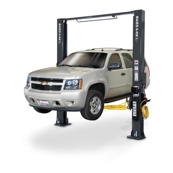
Model XPR-10S shown.
before
using this
Advertisement
Table of Contents

Subscribe to Our Youtube Channel
Related Manuals for BendPak XPR-10 Series


Summary of Contents for BendPak XPR-10 Series
- Page 1 Manual P/N 5900951 — Manual Revision D — May 2019 Models: • XPR-10S • XPR-10AS • XPR-10XLS • XPR-10AXLS Model XPR-10S shown. Designed and engineered by BendPak Inc. in Southern California, USA. Made in China. ⚠ entire before Read the contents of this manual using this product.
- Page 2 Copyright. Copyright © 2019 by BendPak Inc. All rights reserved. You may make copies of this document if you agree that: full attribution goes to BendPak Inc., you are not authorized to make changes to the content, you do not gain any rights to this content, and you will not use the copies for commercial purposes.
-
Page 3: Table Of Contents
Make sure to read and follow the instructions on the labels on the unit. More information about the full line of BendPak products is available at bendpak.com. XPR-10 Series Two-Post Lifts... -
Page 4: Safety Considerations
Technical support and service is available from your dealer, on the Web at bendpak.com/support, by email at techsupport@bendpak.com, or by phone at (800) 253-2363, extension 196. You may also contact BendPak for parts replacement information (please have the model and serial number of your unit available) at (800) 253-2363, extension 191. - Page 5 BendPak assumes no liability for damages resulting from: • Use of the equipment for purposes other than those described in this manual. • Modifications to the equipment without prior, written permission from BendPak. • Damage to the equipment from external influences. •...
-
Page 6: Faq
Concrete. Q: Can I install my Lift outside? A: No. All XPR-10 Series Lifts are approved for indoor installation and use only. Q: How long can I leave a Vehicle raised up on my Lift? A: For a long time, as long as you leave the Lift engaged on its Safety Locks. Once the Lift is Only leave your Lift either on the engaged on its Safety Locks, gravity holds it in position. -
Page 7: Components
Symmetric model shown. Not all components shown. Powerside Post shown on the right. Models with extension pieces are taller. Asymmetric models are angled 30° towards the Approach side. XPR-10 Series Two-Post Lifts P/N 5900951 — Rev. D — May 2019... - Page 8 XPR-10 Series Lift components include: • Powerside Post: The Powerside Post holds the Power Unit, the Safety Lock Release Handle, the Lowering Handle (which is on the Power Unit), and the Power Disconnect Switch. The Powerside Post must be on the Right (looking at the Lift from the Approach) for Asymmetric models;...
-
Page 9: Specifications
Specifications XPR-10 Series Two-Post Lifts P/N 5900951 — Rev. D — May 2019... - Page 10 * Lifting Height w/Pad is maximum lifting height with Pads at lowest height, no adapter. Maximum Lifting Height is maximum lifting height with Pads at top height and with the 2.5" / 63 mm Adapter. Specifications subject to change without notice. XPR-10 Series Two-Post Lifts P/N 5900951 — Rev. D — May 2019...
- Page 11 * Lifting Height w/Pad is maximum lifting height with Pads at lowest height, no adapter. Maximum Lifting Height is maximum lifting height with Pads at top height and with the 2.5" / 63 mm adapter. Specifications subject to change without notice. XPR-10 Series Two-Post Lifts P/N 5900951 — Rev. D — May 2019...
- Page 12 * Lifting Height w/Pad is maximum lifting height with Pads at lowest height, no adapter. Maximum Lifting Height is maximum lifting height with Pads at top height and with the 2.5" / 63 mm adapter. Specifications subject to change without notice. XPR-10 Series Two-Post Lifts P/N 5900951 — Rev. D — May 2019...
- Page 13 * Lifting Height w/Pad is maximum lifting height with Pads at lowest height, no adapter. Maximum Lifting Height is maximum lifting height with Pads at top height and with the 2.5" / 63 mm adapter. Specifications subject to change without notice. XPR-10 Series Two-Post Lifts P/N 5900951 — Rev. D — May 2019...
-
Page 14: Installation Checklist
Installation Checklist Following are the steps needed to install an XPR-10 Series Lift; perform them in this order. ☐ 1. Review the Safety Rules. ☐ 2. Plan for Electrical work. ☐ 3. Make sure you have the necessary Tools. ☐ 4. Review the Installation Orientation. -
Page 15: Installation
Install a Thermal Disconnect Switch. A Thermal Disconnect Switch automatically shuts down the equipment in the event of an overload or an overheated motor. Refer to Installing a Thermal Disconnect Switch for more information. XPR-10 Series Two-Post Lifts P/N 5900951 — Rev. D — May 2019... - Page 16 The Power Unit must go on the Powerside Post. You can identify the Powerside Post by the Mounting Bracket to which the Power Unit attaches; only one Post that came with your Lift has a Mounting Bracket. XPR-10 Series Two-Post Lifts P/N 5900951 — Rev. D — May 2019...
- Page 17 If you are installing an Asymmetric Lift, the Powerside Post and the Power Unit must go on the right. The 30 degree angles of the Posts of an Asymmetric Lift must face the Rear of the Lift. XPR-10 Series Two-Post Lifts P/N 5900951 — Rev. D — May 2019...
- Page 18 Drawing is a top view. Not necessarily to scale. Not all components shown. Additional distance is required for the Front and Rear as Vehicles can be driven in or driven off from these directions. XPR-10 Series Two-Post Lifts P/N 5900951 — Rev. D — May 2019...
- Page 19 Bolts must be more than 6 inches from cracks in the concrete or from a wall. ⚠ CAUTION BendPak Lifts are supplied with installation instructions and concrete anchors that meet the criteria set by the American National Standard “Automotive Lifts – Safety Requirements for Construction, Testing, and Validation”, ANSI/ALI ALCTV-2011.
- Page 20 Important: XPR-10 Series Lifts are shipped from the factory with the Overhead Assembly and the Safety Shutoff Bar already configured in the Narrow Configuration. Refer to Installing the Overhead Assembly, Safety Shutoff Bar, and the for information about switching to the Wide Configuration.
- Page 21 ⚠ CAUTION BendPak recommends wearing gloves while handling the Equalizing Cables. The Equalizing Cables keep the Lift Heads synchronized. You do not want one Lift Head lowering or raising faster than the other Lift Head; the Vehicle on the Lift would become unstable and could fall.
- Page 22 2. Slide the Lift Heads away from the bottoms of both Posts by at least 24 inches / 610 mm, to give yourself some space to work. Not necessarily to scale. Not all components shown. Top view looking at inside of Post. Equalizing Cables not yet in place. XPR-10 Series Two-Post Lifts P/N 5900951 — Rev. D — May 2019...
- Page 23 However, if you mix them up, the Lift will not work correctly and you will have to remove them and then re-install them correctly. XPR-10 Series Two-Post Lifts P/N 5900951 — Rev. D — May 2019...
- Page 24 Head), then leave it resting on top of the Post until later in the installation. 14. Move both Lift Heads back down to the bottom of each Post. XPR-10 Series Two-Post Lifts P/N 5900951 — Rev. D — May 2019...
- Page 25 Adding Extensions Pieces XPR-10 Series models with -168 or -181 in their model names come with Post Extensions that raise the height of the Posts, letting you raise taller Vehicles. The Post Extensions are slipped over the top of both Posts and then bolted into place.
- Page 26 Hydraulic Lines move Hydraulic Fluid to and from the Hydraulic Cylinders at the bottom of each Post. Hydraulic Fittings are used to make connections. All XPR-10 Series Lifts use either three or four Hydraulic Lines: • One Short Hydraulic Line (A in drawing below). Goes from the Power Unit up to the Tee outside Fitting on the Powerside Post;...
- Page 27 Drawing not to scale. Not all components shown. Some components exaggerated for clarity. outside 4. Tighten the Nut on the of the Powerside Post to hold the Tee Hydraulic Fitting in place. XPR-10 Series Two-Post Lifts P/N 5900951 — Rev. D — May 2019...
- Page 28 Connector at the bottom of Hydraulic Cylinder on the Powerside Post. Point the JIC connector towards the side of the Post with the Clips. Not necessarily to scale. Not all components shown. Some components shown exaggerated. XPR-10 Series Two-Post Lifts P/N 5900951 — Rev. D — May 2019...
- Page 29 Hydraulic Cylinder in the Offside Post, with the rest of the Long Hydraulic Line coiled up at the top of the Offside Post. It will be connected to the rest of the Hydraulic System later in the installation. XPR-10 Series Two-Post Lifts P/N 5900951 — Rev. D — May 2019...
- Page 30 Make sure to choose the Width Overall value for the Narrow or Wide orientation, based on the selection you made earlier. Asymmetric The following drawing shows how to create Chalk Line Guides for an Lift. Not necessarily to scale. Not all components shown. XPR-10 Series Two-Post Lifts P/N 5900951 — Rev. D — May 2019...
- Page 31 5. When you move the Posts into position for an Asymmetric Lift, align the correct notches in each of the Bases Plates with the Alignment Chalk Line, as shown in the drawing on the previous page. XPR-10 Series Two-Post Lifts P/N 5900951 — Rev. D — May 2019...
- Page 32 Construction, Testing, and Validation” ANSI/ALI ALCTV-2006. ⚠ WARNING Use only the ALI-certified Anchor Bolts that came with your XPR-10 Series Lift. If you use components from a different source, you void your warranty and compromise the safety of everyone who installs or uses the Lift.
- Page 33 ¾ inch diameter Anchor Bolt, for example, use a ¾ inch diameter drill bit. 5. Vacuum each hole clean. BendPak recommends using a vacuum to get the hole very clean. You can also use a wire brush, make sure to thoroughly clean each hole hand pump, or compressed air;...
- Page 34 Expansion Sleeve contacts the sides of the hole; this is normal. 7. Hammer or mallet the Anchor Bolt the rest of the way down into the hole. Stop when the Washer is snug against the Base Plate. XPR-10 Series Two-Post Lifts P/N 5900951 — Rev. D — May 2019...
- Page 35 Anchor Bolts. Wrenching the Nut forces the Wedge up, forcing out the Expansion Sleeve and pressing it tightly against the Concrete. XPR-10 Series Two-Post Lifts P/N 5900951 — Rev. D — May 2019...
- Page 36 (using the drawings in this section as guides), install the Safety Shutoff Bar, install the Microswitch, and then put the Overhead Assembly into place. BendPak recommends putting the Overhead Assembly on saw horses to prepare it. To prepare and install the Overhead Assembly: 1.
- Page 37 If you are switching the Safety Shutoff Bar from Narrow to Wide Configuration, loosen the Slider Stops, adjust the Safety Shutoff Bar appropriately, then re-tighten the Slider Stops. The following drawing shows the components on the Safety Shutoff Bar. XPR-10 Series Two-Post Lifts P/N 5900951 — Rev. D — May 2019...
- Page 38 Make sure the Microswitch Bracket is on the Powerside. 7. Bolt the Overhead Assembly to the top of the Posts using two Bolts and Nuts on each end. XPR-10 Series Two-Post Lifts P/N 5900951 — Rev. D — May 2019...
- Page 39 Remember, for a Wide Configuration, use the Button End at the very end of the Equalizing Cable. For a Narrow Configuration, use the Button End away from the end of the Equalizing Cable. XPR-10 Series Two-Post Lifts P/N 5900951 — Rev. D — May 2019...
- Page 40 8. Re-install both the Overhead Assembly Sheave, Sheave Pin, and Sheave Pin Bolt. 9. Put the Threaded End of the Equalizing Cable through the hole at the top of the Lift Head, then install the Nut and securely tighten. XPR-10 Series Two-Post Lifts P/N 5900951 — Rev. D — May 2019...
- Page 41 The two ends are t interchangeable. Make sure to orient the Safety Lock Cable so that the loop end goes to the Offside Post side of the Lift. XPR-10 Series Two-Post Lifts P/N 5900951 — Rev. D — May 2019...
- Page 42 Nuts, and two Washers in the Parts Box, put them into place through the top of each Post (they go all the way through the top of the Post), and tighten them in place on both ends. XPR-10 Series Two-Post Lifts P/N 5900951 — Rev. D — May 2019...
- Page 43 To mount the Power Unit: 1. Find the supplied four Hex Bolts, four Nuts, and one Vibration Dampener. The Power Unit is heavy. BendPak recommends having one person hold the Power Unit while a second person bolts it into place.
- Page 44 The Safety Assembly on the Powerside Post includes a handle, which is used to lower the Lift off of its Safety Locks (in conjunction with the Lowering Handle). Not necessarily to scale. Not all components shown. XPR-10 Series Two-Post Lifts P/N 5900951 — Rev. D — May 2019...
- Page 45 3. Put the second Spring on the right end of the Safety Clevis Pin, then install the Cotter Pin on the end of the Safety Clevis Pin. XPR-10 Series Two-Post Lifts P/N 5900951 — Rev. D — May 2019...
- Page 46 8. Operate the Safety Lock Release Handle, checking for proper operation of both Safety Assemblies. ⚠ DANGER Make sure that both the Powerside and the Offside Safety Assemblies engage before properly using the Lift. XPR-10 Series Two-Post Lifts P/N 5900951 — Rev. D — May 2019...
- Page 47 • Connecting the Very Short Hydraulic Line, for Wide Configurations only. All XPR-10 Series Lifts use either three or four Hydraulic Lines: • One Short Hydraulic Line (A). Goes from the Power Unit up to the Tee Hydraulic Fitting on the Powerside Post;...
- Page 48 XPR-10 Series of Lifts. Note: There are multiple ports on the Power Units that are used with XPR-10 Series Lifts. However, each XPR-10 Series Lift uses only one hydraulic pressure out port (labeled P in the drawing above).
- Page 49 3. Tighten the Elbow Hydraulic fitting appropriately; make sure to leave the 06 JIC connector facing up, towards the Tee Hydraulic Fitting. XPR-10 Series Two-Post Lifts P/N 5900951 — Rev. D — May 2019...
- Page 50 8. Connect the Straight End of the Short Hydraulic Line to the 06 JIC connector on the Elbow Hydraulic Fitting; finger tighten the connection. 9. Use appropriate tools to securely tighten all of the finger-tightened connections. XPR-10 Series Two-Post Lifts P/N 5900951 — Rev. D — May 2019...
- Page 51 Short Hydraulic Line (for Wide Configurations) to the 04 JIC connector facing up on the Tee Hydraulic Fitting; finger tighten the connection. 15. Using appropriate tools, securely tighten all of the finger-tightened connections. XPR-10 Series Two-Post Lifts P/N 5900951 — Rev. D — May 2019...
- Page 52 Before installing an Arm Restraint Gear, determine whether it is going to be a ‘left’ arm or a ‘right’ arm (described in Arms) and install the Arm Restraint Gear accordingly. Installing Lift XPR-10 Series Two-Post Lifts P/N 5900951 — Rev. D — May 2019...
- Page 53 For example, if you install an Arm Restraint Gear on a Lift Arm as Left, then it will not work correctly if you put that Lift Arm on the Right side of a Lift Head. XPR-10 Series Two-Post Lifts P/N 5900951 — Rev. D — May 2019...
- Page 54 Arm into a Lift Head. 7. Repeat Steps 5 and 6 for the other two Bolts. The Lift Arm is ready to be installed into the Lift Head. XPR-10 Series Two-Post Lifts P/N 5900951 — Rev. D — May 2019...
- Page 55 Make sure that the Arm Restraint Gears and the Gear Stops are meshing and staying in place when up to 150 pounds of lateral force is applied before putting the Lift into normal operation. XPR-10 Series Two-Post Lifts P/N 5900951 — Rev. D — May 2019...
- Page 56 Anchor Bolts (in order to make it easier to install the Overhead Assembly and to perform final leveling), you can torque them once you have completed final leveling. XPR-10 Series Two-Post Lifts P/N 5900951 — Rev. D — May 2019...
- Page 57 The following procedure assumes the Microswitch is already in place. If it is not, refer to Installing the Overhead Assembly, Safety Shutoff Bar, and the Microswitch to install it. XPR-10 Series Two-Post Lifts P/N 5900951 — Rev. D — May 2019...
- Page 58 Clipping the Microswitch Cable in place keeps it out of the way of the other components. On the Power Unit , open the Electrical Box and wire the Microswitch Cable per the instructions Connecting the Power Unit. XPR-10 Series Two-Post Lifts P/N 5900951 — Rev. D — May 2019...
- Page 59 • Fill the Hydraulic Fluid reservoir. Covered in this section. Your XPR-10 Series Lift is available with one of any of the following types of Power Units: • 220 VAC, 60 Hz, 1 Phase. 220 VAC, for North American countries (U.S., Mexico, Canada).
- Page 60 The Up Button shown in the drawing above could be in a different location on the unit or could be a switch instead of a button, depending on the Power Unit you have. XPR-10 Series Two-Post Lifts P/N 5900951 — Rev. D — May 2019...
- Page 61 Never expose the motor to rain or other damp environments; damage to the motor caused by water is not covered by the warranty. XPR-10 Series Two-Post Lifts P/N 5900951 — Rev. D — May 2019...
- Page 62 Power Unit. A quick flip of the switch immediately cuts power to the Lift. In the case of the XPR-10 Series, the location directly above the Power Unit is being used by the Lowering Handle, so your Electrician may want to move the Power Disconnect Switch location up a little.
- Page 63 6. Fully tighten both Cover Screws into their blocks so that the Safety Cover is held securely. Lubricating the Lift XPR-10 Series Lifts work better and longer if you keep them lubricated. Lubricate the following: • Cable sheave pins, with WD-40 or equivalent.
- Page 64 Lift. It will soon stop doing this, as the Hydraulic System is self-bleeding. 8. Wait for one minute. it cannot be run continuously NOTICE The Power Unit is not a constant duty motor; XPR-10 Series Two-Post Lifts P/N 5900951 — Rev. D — May 2019...
- Page 65 Make sure that all Safety Locks are clear and free. • Make sure an Operational Test has been done. Leave the Manual Make sure to leave the Installation and Operation Manual with the owner/operator. XPR-10 Series Two-Post Lifts P/N 5900951 — Rev. D — May 2019...
-
Page 66: Operation
Check the Lift. Check the Lift for any missing, heavily worn, or damaged parts. Do not operate the Lift if you find any issues; instead, take it out of service, contact your dealer, email techsupport@bendpak.com, or call (800) 253-2363. •... - Page 67 About Lifting Points, Adapters, and Auxiliary Adapters All of the Lifts in the XPR-10 Series are frame-engaging Lifts, which means that the Lift uses its four Lift Arms to raise Vehicles by their frames. This leaves the Wheels of the Vehicle free to be worked on.
- Page 68 Raising a Vehicle This section describes how to raise a Vehicle on your XPR-10 Series Lift. ⚠ WARNING: Never raise a Vehicle whose weight exceeds the rated capacity of the Lift. Do not leave the controls until the Lift is engaged on a Safety Lock position or fully lowered.
- Page 69 Locks and stops moving; Lowering Handle. release Lowering Handle Only leave Lift on Safety when Lift stops. Locks or fully lowered. Only leave Lift on Safety Locks or fully lowered. XPR-10 Series Two-Post Lifts P/N 5900951 — Rev. D — May 2019...
- Page 70 5. When the Lift is on the ground, release both Handles, then move all four Lift Arms to their full drive- through positions. 6. Drive the Vehicle out. XPR-10 Series Two-Post Lifts P/N 5900951 — Rev. D — May 2019...
- Page 71 Lift raised but not engaged on Safety Locks, the Vehicle is not secure . It could fall, possibly damaging the Vehicle, the Lift, and injuring anyone under the Vehicle. XPR-10 Series Two-Post Lifts P/N 5900951 — Rev. D — May 2019...
-
Page 72: Maintenance
⚠ WARNING: Do not operate your Lift if you find maintenance issues; instead, remove it from service, then contact your dealer or BendPak Support via the Web at bendpak.com/support, via email at techsupport@bendpak.com, or by phone at (800) 253-2363. XPR-10 Series Two-Post Lifts... - Page 73 With an awl, probe between wires and strands and lift any wires that appear loose. Evidence of internal broken wires may require a more extensive rope examination. XPR-10 Series Two-Post Lifts P/N 5900951 — Rev. D — May 2019...
-
Page 74: Troubleshooting
Lubricate hinge points using white lithium grease. If you continue to have issues with your Lift, take the Lift out of service, then contact your dealer or BendPak Support at bendpak.com/support, via email at techsupport@bendpak.com, or by phone at (800) 253-2363. - Page 75 If you are unable to find an appropriate facility, the website has resources that may earth911.com be of help. XPR-10 Series Two-Post Lifts P/N 5900951 — Rev. D — May 2019...
-
Page 76: Wiring Diagrams
Lift and cannot be re-energized until all procedures are complete. If your organization has Lockout/ Tagout policies, make sure to implement them after connecting the Lift to power. XPR-10 Series Two-Post Lifts P/N 5900951 — Rev. D — May 2019... -
Page 77: Labels
Labels XPR-10 Series Two-Post Lifts P/N 5900951 — Rev. D — May 2019... - Page 78 XPR-10 Series Two-Post Lifts P/N 5900951 — Rev. D — May 2019...
- Page 79 XPR-10 Series Two-Post Lifts P/N 5900951 — Rev. D — May 2019...
-
Page 80: Parts Drawings
Parts Drawings A complete set of Parts Drawings for XPR-10 Series Lifts is available on the BendPak website. XPR-10 Series Two-Post Lifts P/N 5900951 — Rev. D — May 2019... - Page 81 XPR-10 Series Two-Post Lifts P/N 5900951 — Rev. D — May 2019...
- Page 82 XPR-10 Series Two-Post Lifts P/N 5900951 — Rev. D — May 2019...
- Page 83 XPR-10 Series Two-Post Lifts P/N 5900951 — Rev. D — May 2019...
- Page 84 XPR-10 Series Two-Post Lifts P/N 5900951 — Rev. D — May 2019...
- Page 85 XPR-10 Series Two-Post Lifts P/N 5900951 — Rev. D — May 2019...
- Page 86 XPR-10 Series Two-Post Lifts P/N 5900951 — Rev. D — May 2019...
- Page 87 XPR-10 Series Two-Post Lifts P/N 5900951 — Rev. D — May 2019...
- Page 88 XPR-10 Series Two-Post Lifts P/N 5900951 — Rev. D — May 2019...
- Page 89 A complete set of is available on the BendPak website. Parts Drawings for XPR-10 Series Lifts XPR-10 Series Two-Post Lifts P/N 5900951 — Rev. D — May 2019...
-
Page 90: Ali Store
The ALI Store is your trusted source for workplace safety! Visit today and get the training and materials you need to work safely: www.autolift.org/ali-store/. XPR-10 Series Two-Post Lifts P/N 5900951 — Rev. D — May 2019... -
Page 91: Maintenance Log
Maintenance Log XPR-10 Series Two-Post Lifts P/N 5900951 — Rev. D — May 2019... - Page 92 1645 Lemonwood Drive Santa Paula, CA 93060 USA © 2019 by BendPak Inc. All rights reserved. bendpak.com...
Need help?
Do you have a question about the XPR-10 Series and is the answer not in the manual?
Questions and answers