Sign In
Upload
Download
Table of Contents
Contents
Add to my manuals
Delete from my manuals
Share
URL of this page:
HTML Link:
Bookmark this page
Add
Manual will be automatically added to "My Manuals"
Print this page
×
Bookmark added
×
Added to my manuals
Manuals
Brands
Amprobe Manuals
Test Equipment
PRM-2
User manual
Amprobe PRM-2 User Manual
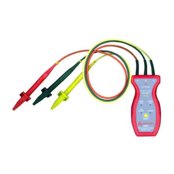
Phase sequence tester
Hide thumbs
1
Table Of Contents
2
3
4
5
6
7
8
9
10
11
12
13
14
15
16
page
of
16
Go
/
16
Contents
Table of Contents
Bookmarks
Table of Contents
Table of Contents
1 Warranty
2 Safety Precautions and Procedures
3 Introduction
Prm-2 Phase Sequence Tester
During Use
Features
Cleaning and Maintenance
Recycling
Technical Data
Prm-3 Phase Sequence & Motor Rotation Tester
During Use
Features
Cleaning and Maintenance
Recycling
Technical Data
Advertisement
Quick Links
Download this manual
PRM-2 PHASE SEQUENCE TESTER
PRM-3 PHASE SEQUENCE & MOTOR ROTATION TESTER
User's Manual
Version 022105
Table of
Contents
Previous
Page
Next
Page
1
2
3
4
5
Advertisement
Table of Contents
Need help?
Do you have a question about the PRM-2 and is the answer not in the manual?
Ask a question
Questions and answers
Related Manuals for Amprobe PRM-2
Test Equipment Amprobe PY-1A User Manual
Ac / dc voltage tester (13 pages)
Test Equipment Amprobe 3503229 User Manual
Ac / dc voltage tester (12 pages)
Test Equipment Amprobe PRM-3 User Manual
Phase sequence tester (16 pages)
Test Equipment Amprobe PRM-6 User Manual
Motor and phase rotation tester (55 pages)
Test Equipment Amprobe PRM-6 User Manual
Motor and phase rotation tester (45 pages)
Test Equipment Amprobe DGC-1000A User Manual
Clamp-on ground resistance tester (20 pages)
Test Equipment Amprobe AM-60 User Manual
Compact dmm with ncv & logic test (20 pages)
Test Equipment Amprobe BAT-500 User Manual
Battery impedance tester (29 pages)
Test Equipment Amprobe RS-3 PRO CAT IV Analog User Manual
Clamp meter series (12 pages)
Test Equipment Amprobe AMB-25 Instruction Manual
Insulation tester (9 pages)
Test Equipment Amprobe DMIII User Manual
(105 pages)
Test Equipment Amprobe gp-2a User Manual
Earth ground tester (62 pages)
Test Equipment Amprobe GROUND PROBE GP-1 User Manual
(20 pages)
Test Equipment Amprobe AMP-25 Calibration Procedure
(7 pages)
Test Equipment Amprobe AMB-55 User Manual
5000v insulation resistance tester (52 pages)
Test Equipment Amprobe ACD-14 Instruction Manual
Tech clamp (16 pages)
This manual is also suitable for:
Prm-3
Table of Contents
Print
Rename the bookmark
Delete bookmark?
Delete from my manuals?
Login
Sign In
OR
Sign in with Facebook
Sign in with Google
Upload manual
Upload from disk
Upload from URL


Need help?
Do you have a question about the PRM-2 and is the answer not in the manual?
Questions and answers