Table of Contents
Advertisement
Quick Links
Advertisement
Table of Contents

Subscribe to Our Youtube Channel
Related Manuals for Amprobe MEGATEST 5000


Summary of Contents for Amprobe MEGATEST 5000
- Page 1 MEGATEST 5000 5000 V MEGOHMMETER Model#: AMB-5 KVD Owner’s Manual...
-
Page 3: Table Of Contents
ACCIDENT PREVENTION AND SAFETY MEASURES....................2 ..................................2 URING USE ..................................3 FTER USE OVERVIEW....................................4 ..............................5 URPOSE OF THE DEVICE ............................... 5 EASURING PRINCIPLE ............................5 HAT IS INSULATION RESISTANCE ............................5 OSSIBLE FIELDS OF APPLICATION 2.4.1 Other possible fields of employment ........................6 ................................ -
Page 4: Accident Prevention And Safety Measures
1. Accident prevention and safety measures Please read and understand these instructions BEFORE using the AMB-5KV-D. This instrument can generate dangerously high voltages. Only specialised personnel, well trained about electricity and its effects must use it. When testing, the following is important: •... -
Page 5: After Use
When measuring insulation: Cut power off from the installation before preparing for the tests. Seal off the testing area and do not allow other people to approach it throughout the duration of the tests. Seal off the installation being tested, disconnecting those branches of it which are not involved in the test. -
Page 6: Overview
Thank you for purchasing one of our instruments, we are a leading company in the field of electrical measuring equipment. Amprobe has been in the marketplace for over 50 years, and intends to satisfy our customers’ requirements by providing increasingly reliable and innovative products. -
Page 7: Purpose Of The Device
2.1 Purpose of the device This instrument can be used to measure the insulation of installations, equipment, insulating material and so on. Testing must be performed with no other voltage present, and after having disconnected the parts not being measured or which are unable to withstand the testing voltage. This instrument is also able to measure the voltage present before the test, to display it and to inhibit starting up of the measurement in case the tested element should be live. -
Page 8: Other Possible Fields Of Employment
When the meter is in its "TIMER" mode, set a duration of 10’ to determine the efficiency of an insulator at a certain voltage. During the test, insulation resistance may diminish, remain steady or increase. Diminishing resistance means insulation is not good. On the contrary, the more the resistance increases the better the insulation. -
Page 9: Notes On Insulation Measurements
2.6 Notes on insulation measurements Measurement of such a high resistance as insulation resistance is very critical, since the currents involved are minute, even lower than those circulating inside our nervous system. When performing measurements, in order to avoid making mistakes take the following precautions: •... -
Page 10: Preparing The Instrument For Use
3 Preparing the instrument for use 3.1 Initial checks Before being shipped, the instrument is checked from an electrical and a mechanical point of view. Every precaution has been taken so the instrument can be delivered without damage. However the user is advised to look the instrument over quickly in order to check for any damage during shipment. -
Page 11: Working Instructions
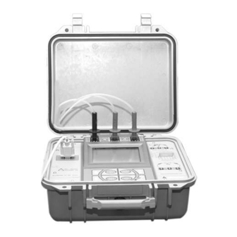
4 Working instructions 4.1 Description of the instrument Legend: 1. Instrument ON/OFF switch. 2. Negative high voltage jack. 3. GUARD jack. 4. Positive high voltage jack. 5. An example of measurement connection using the GUARD. 6. Measuring range graph. 7. Display. 8. -
Page 12: Display
4.2 Display Legend: 1. "Measuring underway" indicators. When flashing: voltage delivery; when fixed ON: circuit discharge. 2. "Measured value" indicator or indication of the current parameter memory number. 3. Unit of measure. 4. "Low Battery” indicator. 5. "Current measuring mode" indicator. 6. -
Page 13: Keyboard
4.3 Keyboard Legend: 1. Decrease key This modifies the voltage or time setting. This displays the locations of the measurement models. 2. Increase key This displays the saved performed measurements. 3. Confirmation or end of current operation. 4. Choosing the mode (MAN / AUTO / TIMER / PROGR) or deletion procedure. 5. -
Page 14: Summary Of The Measuring Modes
4.4 Summary of the measuring modes The instrument was designed for simple programming, so as to cut down the time needed to prepare measuring. The instrument is equipped with 25 memory locations (parameters – P) for storing the various ways of measuring: Configuration Factory setting Modifiable... -
Page 15: Factory-Set Configurations
4.4.1 Factory-set configurations Following are the keyboard sequences for obtaining the configurations, with the instrument at rest, starting from programme P01 P n. Keyboard sequence Parameters Kind of test once the Diminish key, twice the Start key 1’ (minute) Timer twice the Diminish key, twice the Start key 1000 1’... -
Page 16: Previously Memorised Configurations
4.4.2 Previously memorised configurations When performing the same measurements on the same kind of equipment, a measuring configuration can be memorised for each usual situation, for example: • P01 Measuring on A-type product. • P02 Measuring on B-type product. • P03 Measuring on C-type product. -
Page 17: Instrument Configuration And Measurement Performance
4.5 Instrument configuration and measurement performance Following is a description of the parameters and way the values are set. 4.5.1 Measurement preparation selection To prepare the measurement, press the increase or decrease key to run through the memories until reaching the location you intend to introduce the configuration into. NOTICE Memorisation is possible only from cell P01 to cell P19. -
Page 18: Timer Mode
4.5.4 TIMER Mode TIMER OPERATION Reach the memory cell you are interested in. ModE Press the MODE key repeatedly to display the TIMER measuring mode. The V2 parameter indicator is flashing. Set the V2 voltage value you want (testing voltage). The top secondary (item 10 par. -
Page 19: Measurement Of Polarization Index
Set the V1 voltage value you want (testing start voltage). The top secondary display (item 10 par. 4.2) will show the value you are setting. NOTE: The value of V1 CANNOT be greater than that of V2. The T1 parameter indicator is flashing. Set the T1 time value (duration of the rising voltage ramp from value V1 to value V2). - Page 20 This measuring method, based on resistance ratios, gives a dimensionless result, independent on a series of factors such us equipment size, temperature or environmental conditions. Insulator status 60/30 sec ratio Polarization index 10/1 min ratio dangerous ─── less than 1 1.0 ÷...
-
Page 21: Examples Of Insulation Measurement
4.6 Examples of insulation measurement Connect the terminals of the insulation you want to measure to the high voltage jacks. Connect the Guard to a suitable point near the negative terminal (ref. "Use of the GUARD" – heading 2.5). WARNING Comply with the instructions in the manual, especially refer to chapter 1. -
Page 22: Measuring On A Power Plant
• Press START, wait until the measuring is over and make sure the value measured is consistent with what you requested. • If necessary, save the measurement you performed by pressing the SAVE key (ref. chapter 4.7). 4.6.2 Measuring on a power plant Technicians and repair engineers may use this instrument in order to check out the efficiency of the system and its compliance with specific regulations. -
Page 23: Estimating The Insulating Strength
This measurement can be employed by manufacturers of electrical equipment to check materials, such as supports for conductors, components and equipment. • Connect the test leads to the material being tested, placing them at the distance to be verified and making sure there is proper contact. •... -
Page 24: Saving The Measurements Which Were Performed
4.7 Saving the measurements which were performed Once measurement has been finished, you can press the SAVE key to save the performed measurement with all the parameters employed during testing. The top secondary display (item 10 par. 4.2) shows for three seconds the number of the memory location where the measurement was memorised. -
Page 25: Deleting Memorised Memories
4.10 Deleting memorised memories OPERATION Recall With the instrument in waiting condition (i.e. when there are no current operations), press Recall to enter the measurement display mode. This reaches the memory location you want to start deleting with. The number of the measurement is shown on the top secondary display (item 10 par. -
Page 26: Use Of The Serial Port
4.13 Use of the serial port Connect the instrument to the serial port of your PC using the 9 pin RS 232 serial cable provided. In case your PC has a 25-pin connector simply use a standard 9 pin to 25 pin adapter (not provided) 4.13.1 Reading and downloading the results of the measurements on a computer If the “SUPERLINK”... -
Page 27: Maintenance
5 Maintenance 5.1 Replacing the batteries CAUTION • Before opening the lid of the battery compartment, disconnect the test leads from the instrument. • Always make sure the system has finished discharging before disconnecting the test leads or opening the battery compartment. When the "low battery”... -
Page 28: Technical Specifications
6 Technical specifications 6.1 Technical features Accuracy is shown in terms of [% of the reading + number of digits]. It refers to the following ambient conditions: temperature 73°F +/- 2° (23 °C +/- 1°) with relative humidity < 75%. 6.1.1 Measuring the insulation. -
Page 29: General Features
6.2 General features 6.2.1 Electric features Measuring method: voltamperometric system Parameter memory: 20 different parameters Stored measurements: 200 measurements with their parameters and results RS232: DIN 9 pin 6.2.2 Safety The measurement is stopped when there is voltage at the test leads that could damage the instrument. -
Page 30: Standard Equipment
6.4 Standard equipment The package contains: • The instrument received • Three test leads provided with a safety boot and an alligator clip • Instruction manual • Serial cable for computer connection • CD-ROM with “SUPERLINK” software for downloading/reading measurements 6.5 Replacement parts Part Description Part #... -
Page 31: Warranty Conditions
7 Warranty conditions Congratulations! You are now the owner of an AMPROBE Instrument. It has been quality crafted according to quality standards and contains quality components and workmanship. This instrument has been inspected for proper operation of all of its functions. It has been tested by qualified factory technicians according to the long -established standards of AMPROBE INSTRUMENT. - Page 32 Miami, FL 33150 (305) 423-7500 (800) 327-5060...
Need help?
Do you have a question about the MEGATEST 5000 and is the answer not in the manual?
Questions and answers