Table of Contents
Advertisement
Quick Links
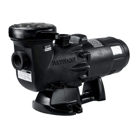
HAYWARD Hi-Performance SELF-PRIMING PUMPS
INSTALLATION AND OPERATING INSTRUCTIONS
Turbo Flo II
Your Hayward Turbo Flo II pump has been quality and
engineered to give you many years of e cient, dependable
service. The non-conductive, corrosion-proof motor housing
provides protection from the elements and insulates the
electrical motor parts from outside contact.
The advanced design reduced operation and maintenance to
simple, common-sense procedures.
GENERAL TIPS ON PUMP INSTALLATION
For best pump performance, locate the system below the pool
water line and as close to the pool as possible. If you own an
above ground pool please see Note: NSPI-4 Article V, for safe and
proper installation of the equipment package. Make sure
suction joints are tight. Suction pipe should be as large or larger
than discharge pipe.
Damp, non-ventilated locations should be avoided. Motors
require free circulation of air to aid in cooling.
Insure that the electrical supply available agrees with the
motor's voltage, phase and cycle, and that wire size is adequate
for the HP/KW rating and distance from the power source. Motor
must always be properly grounded. If cord connected, use only
a properly grounded outlet. Electrical circuits should be
protected by proper size ground fault circuit interrupter (GFCI).
All electrical wiring should be performed by quali ed personnel
and must conform to local codes and regulations.
MAINTENANCE
1.
Clean strainer basket regularly. Do not strike basket to clean.
Inspect strainer cover gasket regularly and replace as necessary.
2.
Hayward pumps have self-lubricating motor bearings and shaft
seals. No lubrication is necessary.
3.
Keep motor housing clean. Insure air vents are free from
obstructions, debris, etc.
MANUFACTURED EXCLUSIVELY BY HAYWARD
2880 PLYMOUTH DRIVE, OAKVILLE, ONTARIO L6H 5R4
® Hayward Pool Products Canada, Inc. -- Licensee
Fill strainer/housing completely with water. Never operate the
pump without water. Water acts as a coolant and lubricant for
the mechanical shaft seal.
Open all suction and discharge lines and valves, as well as air
bleed (if available) on lter. (The air that is to be displaced from
the suction line must have some place to go).
Turn on power and allow a reasonable time for priming. Priming
time depends on suction lift and length of suction piping. If
pump will not start, or will not prime, see TROUBLE SHOOTING
GUIDE on back page.
Note: NSPI-4 Article V, standard for above ground and on
ground pools, advises that components such as the ltration
system, pumps and heater be positioned so as to prevent their
being used as a means of access to the pool by young children.
www.haywardcanada.com
STARTING AND PRIMING INSTRUCTIONS
4. Occasionally, shaft seals must be replaced, due to wear or
damage. See instructions
STORAGE/WINTERIZING
Pump and motor must be protected from freezing. Shut o all
electric power. Disconnect cord/electrical connections and
plumbing connections. Drain thoroughly and clean out any
debris. Store pump and motor in a dry, well ventilated room.
1-888-238-POOL
IS 5700 HC-08
Advertisement
Table of Contents

Related Manuals for Hayward Turbo Flo II


Summary of Contents for Hayward Turbo Flo II
- Page 1 HAYWARD Hi-Performance SELF-PRIMING PUMPS INSTALLATION AND OPERATING INSTRUCTIONS Turbo Flo II Your Hayward Turbo Flo II pump has been quality and engineered to give you many years of e cient, dependable service. The non-conductive, corrosion-proof motor housing provides protection from the elements and insulates the electrical motor parts from outside contact.
- Page 2 PART NUMBER DESCRIPTION MODEL MODEL Req’d SP-2295 (ET) SP2290 (ET) SP1680E SP1680E Strainer Cover SP1500P SP1500P Strainer Cover w/o-ring SP1500LX SP1500LX Basket SP1500CP SP1500CP Strainer Housing SP1700FG SP1700FG Drain Plug (optional) SP1700FG SP1700FG Drain Plug w/Gasket SP1500W SP1500W O-ring SP1500N2 SP1500N2 Bolt, No.
- Page 3 PARTS LISTING Ref No. Part# Description No. Required SP5700DL Strainer Cover Assy SP2700Z4 Strainer O-ring SP2700M Strainer Basket SP5700A Pump Housing SP1495Z1 O-ring SP2700Z3 Screw SP5700B Diffuser SP1591E 1 HP Impeller SP1591F 1.5 HP Impeller SP5500H O-ring SP1250XZ2C Shaft Seal SP5700E Seal Plate 6060Z1...
- Page 4 WARNING - To reduce the risk of injury, do not permit children to use this product. B. Disconnect all electrical power service to pump before beginning shaft seal replacement. C. Only quali ed personnel should attempt rotary seal replacement. Contact your local authorized Hayward Dealer or service center if you have any questions.
- Page 5 SERVICE AND REPAIRS Consult your local authorized Hayward dealer or service center. No pumps or motors may be returned directly to the factory without the express written authorization of Hayward Pool Products Canada, Inc.
Need help?
Do you have a question about the Turbo Flo II and is the answer not in the manual?
Questions and answers