Advertisement
Quick Links
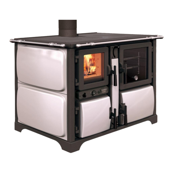
THERMOROSSI
BOSKY 25,30 & F25, F30
COUNTRY, COUNTRY F
INSTALLATION, USER &
SERVICE MANUAL
VER 1 10/2015
THERMOROSSI UK,
BLYTH ROAD, HARWORTH, DONCASTER UK DN11 8NE
tel. (0044) 1302742520 fax 01302 750573
EMAIL - technical@thermorossi.co.uk
www.thermorossi.co.uk
Advertisement


Need help?
Do you have a question about the BOSKY 25 and is the answer not in the manual?
Questions and answers