Table of Contents
Advertisement
Quick Links
Advertisement
Chapters
Table of Contents

Subscribe to Our Youtube Channel
Related Manuals for Cooper Security Homelink 75


Summary of Contents for Cooper Security Homelink 75
- Page 1 Homelink 75 Security System Administrator’s Guide...
-
Page 2: Table Of Contents
Contents Introduction ............3 Controls and Displays ..........5 The Display ............6 Keys:.............7 Administration............. 8 Entering the User Menu ........8 Voice Memo ............9 Recording a Voice Memo........9 Deleting a Voice Memo ........9 Omit Zones ............10 Users .............. 11 Adding Users ..........11 Editing Existing Users........ -
Page 3: Introduction
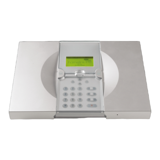
Introduction The Homelink75 is a wireless intruder alarm system that provides several features specially for domestic use. These include social alarm monitoring (including remote listen-in capabilities), inactivity alarm monitoring, direct communication to mobile telephones and voice messaging. The heart of the Homelink75 system is the 7510r control unit. - Page 4 Introduction 1. Single button pendant panic alarm. 2. Single button wrist/pendant panic alarm. 3. Two button panic alarm. 4. Two button panic alarm with tiltswitch. 5. Four button telecommand. 6. Door Contact/Universal Transmitter. 7. Smoke Detector. 8. Passive Infra Red. 9.
-
Page 5: Controls And Displays
Introduction Controls and Displays Figure 2 shows the controls and displays available on the control unit. 1. LCD display . 5. Unset key. 2. Set key. 6. Emergency keys. 3. Navigation and “soft” keys. 7. Social care alarm key. 4. Numeric keypad. 8. -
Page 6: The Display
Introduction The Display The display shows messages and prompts to help guide you through setting, unsetting and programming the system. When the system is idle (either while set or unset) the display shows the “standby screen”, comprising the time and date: 01:12 01/01/2004... -
Page 7: Keys
Introduction Keys: Full sets the system. Unsets the system. Scroll up. Scroll down. (no markings) The function of these keys depends on the guiding text shown on the bottom line of the display above the keys. In the instructions on the following pages a name shown in capitals, for example SELECT or DONE, means the key under that word in the bottom line of the display. -
Page 8: Administration
Administration To make changes to the way your system works you must enter the User Menu. Your degree of access to the User Menu depends on what type of user you are: Administrator or Normal User. An Administrator has access to all the options of the User Menu. A Normal User: Can change their own access code. -
Page 9: Voice Memo
Administration Voice Memo You can leave a short voice message on the system. Any user can play back the message, either when they unset the system or by entering User Menu – Voice Memo – Play Message. The standby screen shows a small icon ) to indicate that a message is waiting (see page 8). -
Page 10: Omit Zones
Administration Omit Zones You may wish to prevent a zone causing an alarm. For example, if you have a fire door that is normally closed and protected by a detector you may wish to leave it open for fresh air or to move goods in and out. To do this the control unit allows you to "Omit"... -
Page 11: Users
Administration Users The control unit can recognise up to 50 individual users. Select Users in the User Menu to add new users, change their details, or delete them from the system. Adding Users Note: When adding a new user you can also assign them to partitions, and allocate them proximity tags, telecommands, pendants and panic alarm transmitters. -
Page 12: Type
Administration A B C Æ Å Ä D E F J K L M N O Ø Ö G H I P Q R S T U V W X Y Z Space'():.-!& Figure 3. Letters Assigned to Keys User Types When you complete the user name, the display shows which user types are available. -
Page 13: Tag
Administration Access Code After assigning users to one or more partitions, the display requests you to assign an access code to the user. Key in an access code for the user. When you press the last digit of the access code the display asks you to key in the same access code again. -
Page 14: Telecommands
Administration Telecommands A telecommand is a small remote control that you can attach to a keyring. The telecommand has four buttons and a small light that glows when the telecommand transmits a signal. When delivered from the factory three of the buttons are dedicated to setting or unsetting the system (see Figure 4). -
Page 15: Pendants
Administration Press any button on the telecommand that you wish to register. When you press the button the control unit learns the identity of the telecommand and registers it to the user. (The display then asks if you wish to register a pendant.) If you do not wish to register a telecommand press "NO TELECOMMAND". -
Page 16: Editing Existing Users
Administration PA (Panic Alarms) A PA is a two button telecommand, used to start a Panic Alarm. To activate the transmitter you must press both buttons at the same time. A third button acts as a lock so that you can prevent the PA going off when carrying it in your pocket. -
Page 17: Deleting Users
Administration Select the option you wish to edit. The options available are the same as those shown when adding a user. Press DONE when you have finished. Note that you can delete tags, telecommands, pendants and PAs from each user. If you wish to reprogram the function of telecommand buttons see page 23. -
Page 18: Facilities On/Off
Administration Facilities On/Off You can switch the following facilities on or off: When you The control unit: switch on: Chime Gives a tone whenever something triggers a zone programmed with the Chime attribute. Voice Prompts Uses a pre-recorded voice message to announce the setting and unsetting stages of the system Activity... -
Page 19: Test
Administration Test If you think that part of the system is not working correctly then you can use the Test option to test various peripherals. If the test confirms that part of the system is not working then contact your installer. The Test option also lets you check the identity of Telecommands, Pendants and Tags. -
Page 20: Outputs
Administration Outputs The display shows a list of the outputs installed on the system. Select the output you wish to test. Press DONE to finish the test. NOTE: Make sure no one tries to activate the radio output module using a telecommand or pendant when you perform the test. -
Page 21: System Configuration
Administration System Configuration The System Configuration option allows you to set up parts of the system to suit your particular needs. If you need more extensive changes to the operation of the system then you can select Menu - Call to Downloader to connect your control unit to an installer's PC. - Page 22 Administration During programming the installer may allocate some outputs so that they can be reprogrammed by an Administrator. The following section describes how the Administrator can use those outputs. Programming an Output Channel If you wish to program an output that an installer has allocated for use by an Administrator: In the User Menu select System Config - Outputs - Edit Output.
-
Page 23: Re-Programming Telecommands For Users
Administration Re-Programming Telecommands for Users The System Config - Telecommands option allows you to re-program buttons on a telecommand. Enter the User Menu and select System Config - Telecommands - Edit. Press the button you want to reprogram on the telecommand. -
Page 24: Starting A Call To Downloader
Administration Note: If you do not have the device press "NO TELECOMMAND". The display shows a list of the registered devices. Select the device you wish to delete. The display shows the details of the device you have selected. Press YES to confirm that you wish to delete the device. -
Page 25: Summer/Winter Time
Administration To start the call: Enter the User Menu and select System Config - Call Downloader. The display shows the Call to Downloader menu. Select Telephone Number 1 or 2, or IP Address 1 or 2 as instructed by your installer. The control unit calls the installer's computer on the number you selected. -
Page 26: Message Volume
Administration Message Volume If you have voice prompts switched on (see page 18), then you may wish to adjust their volume. Enter the User Menu and select System Config – Message Volume. The display shows “Message Volume – Set Volume” Press u to make voice prompts lounder, or n to make them quieter. -
Page 27: About Comms
Administration About Comms If you wish to check what type of telecommunication line your control unit has, enter the User Menu and select System Config – About Comms. The display shows “PSTN” if your control unit is connected to a land line, “GSM” if you have a GSM module, or “ISDN”... -
Page 28: Outputs
Administration Outputs You can operate radio output modules from the keypad, as well as by using a telecommand. To operate an output: Enter the User Menu and select Outputs. The display shows a list of outputs. Use the u or n keys to select the output you want to operate and then press CHANGE. - Page 29 Administration used by many mobile phone providers to register SIM cards and check their credit level. If you attempt two way speech then a person at the far end of the line may find it difficult to hear you well. To start a telephone call: Enter the User Menu and select Telephone Call.
-
Page 30: List Of Menu Options
Administration List of Menu Options Item Page Voice Memo Play Record Delete Omit Zones (Zone 01, 02, …) Users Edit User (for each user:) Name Type Partitions Code Telecommands Pendants Add User Delete User View Log Facilities On/Off Chime Voice prompts Activity monitor Test Siren... - Page 31 Administration Item (cont’d) Page System Config Set Date & Time Ouputs Telecommands Call Downloader Summer/Winter Time Message Volume Installer Access About Comms Follow Me Follow Me Number Outputs Output 01, 02, … Telephone Call Number to Dial Page 31...
- Page 32 © Cooper Security Ltd. 2006 Every effort has been made to ensure that the contents of this book are correct. However, neither the authors nor Cooper Security Limited accept any liability for loss or damage caused or alleged to be caused directly or indirectly by this book.
Need help?
Do you have a question about the Homelink 75 and is the answer not in the manual?
Questions and answers