Advertisement
Quick Links
Download this manual
See also:
Building Instructions
Build Instructions
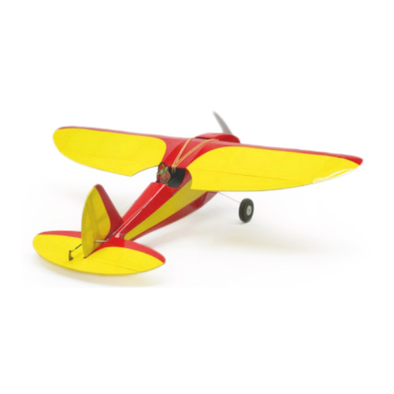
Swift (100)
A Full House Ultra Micro AeroBat!
By Stevens AeroModel
Length 17 inches | Span 21 inches | Area: 92 inches
2
| Flying Weight 3.0 oz.
Version 05/26/2011
© 2011 Stevens AeroModel all rights reserved.!
Page 1 of 10
Advertisement

Subscribe to Our Youtube Channel
Related Manuals for Stevens AeroModel Swift 100


Summary of Contents for Stevens AeroModel Swift 100
- Page 1 Swift (100) A Full House Ultra Micro AeroBat! By Stevens AeroModel Length 17 inches | Span 21 inches | Area: 92 inches | Flying Weight 3.0 oz. Version 05/26/2011 © 2011 Stevens AeroModel all rights reserved.! Page 1 of 10...
- Page 2 Build Instructions WARRANTY Stevens AeroModel guarantees this kit to be free from defects in both material and workmanship at the date of purchase. This warranty does not cover any component parts damaged by use or modification. In no case shall Stevens AeroModel’s liability exceed the original cost of the purchased kit. Further, Stevens AeroModel reserves the right to change or modify this warranty without notice.
-
Page 3: Kit Contents
☐ 1/2 in. wide clear tape [MMM190] ☐ Servo mounting tape [DUB634] ☐ Adhesive Backed Velcro [DUB348] ☐ Soldering Iron ☐ 1/8 in. Drill Bits (2) ☐ Paste Glue Stick or 3M 77 © 2011 Stevens AeroModel all rights reserved.! Page 3 of 10... - Page 4 (use no glue) the parts together first. It’s advised to work 1-2 steps ahead in the instructions using this dry-fit technique which allows ample opportunity to © 2011 Stevens AeroModel all rights reserved.! Page 4 of 10...
- Page 5 8. Fit F9 to fuselage side and F2. Tack glue to fuselage. retain. 9. Fit F10 to back of F9, fuselage side, and F2. Once satisfied with fit bond F9 to F10. © 2011 Stevens AeroModel all rights reserved.! Page 5 of 10...
- Page 6 CA. Lightly sand stabilizer, rounding the leading edge and leaving the trailing edge 34. Fit rib W3 to outer slot of spar W1. Refer square. back to plan for part placement. © 2011 Stevens AeroModel all rights reserved.! Page 6 of 10...
-
Page 7: Final Assembly
47. Bond the balsa servo cuffs W13 to the covering over the wing dowel holes in front of BOTTOM of each servo mounting plate, to the wing saddle. create a pocket for the servo to rest in. © 2011 Stevens AeroModel all rights reserved.! Page 7 of 10... - Page 8 “General Pushrod Detail” on the wing plan the connector and soldering on a JST sheet to create and connect the pushrods for the ailerons. Mount pushrods in the outer © 2011 Stevens AeroModel all rights reserved.! Page 8 of 10...
- Page 9 The above exponential settings apply only to a flight with a partially charged battery. computer radios. ☐ Clear prop! Before applying power to the model, clear and keep clear of the prop arc. © 2011 Stevens AeroModel all rights reserved.! Page 9 of 10...
- Page 10 You may correspond with ☐ Check for traffic. Proceed to the flight line Stevens AeroModel staff using any of the (With your mentor/instructor if you are a following methods: novice pilot) and observe other RC traffic.
Need help?
Do you have a question about the Swift 100 and is the answer not in the manual?
Questions and answers