
Related Manuals for wiwa INJECT 2K 14015


Summary of Contents for wiwa INJECT 2K 14015
- Page 1 Operation Manual INJECT 2K 14015/14025 GX Type: 14015 14025 Serial No.: 2ia14015_BA_en_B0550058 ✓(2021/12/01)
-
Page 2: Ec Declaration Of Conformity
EC declaration of conformity in accordance with Annex II, No. 1 A of Machine Directive 2006 / 42 / EC, as amended by 2009 / 127 / EC The company WIWA Wilhelm Wagner GmbH & Co. KG 35633 Lahnau Gewerbestraße 1–3 Germany... -
Page 3: Table Of Contents
Contents Contents 1 Foreword 2 Safety 2.1 Explanation of symbols ......2.2 Safety notes ....... 2.2.1 Working pressure . - Page 4 Contents 4 Transport, installation, and assembly 4.1 Transport ....... . 27 4.2 Installation site .
-
Page 5: Foreword
If questions should arise, we would be happy to assist you. We wish you excellent working results with your machine WIWA Wilhelm Wagner GmbH & Co. KG Copyright © 2025 WIWA The copyright to this operation manual belongs to WIWA Wilhelm Wagner GmbH &... -
Page 6: Safety
We recommend that the machine owner have this confirmed in writing. 2.1 Explanation of symbols Safety notes warn of potential accident risks and describe the measures required for accident prevention. In the WIWA operation manuals, safety notes are high- lighted and labeled as follows: DANGER... - Page 7 Safety General risk of accident Risk of explosion due to explosive atmosphere Risk of explosion due to explosive substances Risk of accident due to electricity or electrostatic charge Warning of crushing Warning of corrosive substances Risk of injuries due to rotating machine parts Risk of burning due to hot surfaces Risk of freezing due to cold surfaces The first line of the safety instructions indicates the personal protective equipment...
-
Page 8: Safety Notes
Safety Wear protective gloves Signals an instruction to wear protective gloves in order to prevent injuries due to aggressive chemicals, burns when processing heated materials, or freezing due to contact with very cold surfaces. Wear safety shoes Signals an instruction to wear safety shoes, in order to prevent foot injuries due to falling, toppling or rolling objects, as well as slipping on slippery floors. -
Page 9: Working Pressure
Safety 2.2.1 Working pressure WARNING Parts that are not designed for the maximum permissible working pressure may rupture and cause serious injuries. It is essential to observe the prescribed maximum working pressures for all parts. With varying working pressures, the lowest value always applies as the maximum working pressure for the complete machine. -
Page 10: Risks Due To Electricity
Never spray solvents or materials containing solvents into narrow-mouthed cans or drums with a bung opening! Only use electrically conductive material hoses. All original material hoses from WIWA are conductive and designed for our devices. Only use electrically conductive accessories/accessory parts. WARNING Dirty machines can become electrostatically charged. -
Page 11: Explosion Protection
Safety 2.2.6 Explosion protection The following short designations are used in the instructions of WIWA: Ex protection: Explosion protection Ex area: potentially explosive or non-explosion protected area Non-Ex area: non-explosive or explosion protected area Ex zone: Explosion protection zone according to ATEX Directive... -
Page 12: Safety Features
Safety When handling paint, solvents, oils, greases, and other chemical substances, observe the safety and portioning instructions of the manufacturer and the generally applicable regulations. Only use suitable skin protection, skin cleansing and skincare products for cleansing the skin. In systems that are closed or under pressure, dangerous chemical reactions may arise, if parts produced from aluminum or galvanized parts come into contact with 1,1,1 - trichloroethane, methylene chloride or other solvents that contain halogenated chlorinated hydrocarbons (CFCs). -
Page 13: Safety Valve
Safety Checklist on the pressureless machine: Seal on the safety valve OK? Safety valve externally free of damage? Ground cable free of damage? Mobility of the compressed air shut-off valve OK? Checklist on the pressurized machine: Function of the safety valve OK? (For function test, see section 6.3.1 on page 45.) When checking additional safety features, observe the operation manuals for the optional accessories. -
Page 14: Ground Cable
Safety The functional principle of all compressed air shut-off valves installed on the machine is the same: Open ⇒ Position ball valve in the flow direc- tion Close ⇒ Position ball valve transverse to the flow direction Fig. 2: Example of compressed air shut-off valve After shutting off the air, the machine remains under pressure. -
Page 15: Personnel Qualifications
Safety 2.4.2 Personnel qualifications Differentiation is made between two groups of personnel, depending on their qualifications: Instructed operators have received verified instruction from the machine owner regarding the tasks entrusted to him and the possible risks if the correct procedure is not followed. Trained personnel have received instruction provided by the machine manu- facturer and are capable of carrying out maintenance and repair work on the machine, independently recognizing possible dangers and avoiding risks. -
Page 16: Warranty And Liability
When repairing and maintaining the machine, original spare parts from WIWA must be used. If spare parts are used that have not been produced or supplied by WIWA, the warranty is void and all liability shall be excluded. 2.5.2 Accessories If you use original WIWA accessories, their suitability for use in our machines is guaranteed. -
Page 17: Leakage
Safety 2. Actuate the lever on the mixing unit again briefly so that no material pressure is present. CAUTION Despite pressure relief, a residual pressure can remain in the machine. Exercise particular caution when proceeding further. This process is not suitable for decommissioning. The machine is not flushed. For controlled decommissioning, please observe section 5.8 on page 41. -
Page 18: Description
3.1 Intended use Using the INJECT 2K 14015/14025 GX, 2-component materials with a fixed mixing ratio can be injected. The machine is intended for use in building renovation to seal cracks, insert moisture barriers and fill cavities, among other things. Low to medium-viscosity resins, foams, water or solvent-based gels, as well as glues and adhesives, for example, can be processed. -
Page 19: Construction
Description spare parts are installed that were not manufactured or delivered by WIWA (see section 2.5.1 on page 12), accessories are used that are not suitable for the machine (see section 2.5.2 on page 12), machines without identification are used in potentially explosive atmo-... -
Page 20: Design Without Flush Pump
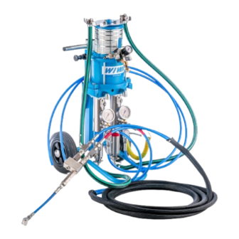
Proportioning pump Cycle counter Ground cable Cart Flush pump Material suction hose for flushing agent *) optional 3.3.2 Design without flush pump Fig. 5: Inject 2K 14015 without flush pump on stand frame Original Operation Manual ✓(2021/12/01), Status: 2024/11/11 2ia14015_BA_en_B0550058... -
Page 21: Compressed Air Connection
Description Description Pressure gauge for material pressure display of component A Water separator attachment kit Circulation ball valve for component A Material suction hose for component A Hose holder Compressed air regulator Pressure gauge for material pressure display of component B Return/circulation ball valve for component B Material suction hose for component B Mixing unit without separate flushing function... -
Page 22: Compressed Air Connection For The Design With Flush Pump
3.4.1 Compressed air connection for the design with flush pump Separate compressed air regulators are present for the proportioning pump and flush pump. The INJECT 2K 14015/14025 GX with a flush pump is factory-equipped with a compressed air regulator cluster. Fig. 6: Compressed air regulator cluster... -
Page 23: Proportioning Pump
1:1 to 10:1 are possible. Changing the mixing ratio changes the pressure ratio and therefore also the maximum permissible air inlet pressure. In this case, the safety valve for the proportioning pump must be replaced after consultation with WIWA. Designation Air motor... -
Page 24: Flush Pump
Description Always pay attention to the correct component assignment. The two components of the processing material may only come in contact with the intended machine parts: blue = standard component (A) red = hardener (B) 3.6 Flush pump The flush pump operates in flushing mode to transport the flushing agent from the flushing agent containers via the mixing unit to the spray gun. -
Page 25: Frames
Description 3.7 Frames The INJECT 2K 14015/14025 GX is custom-mounted on a stand frame or cart, wherein the option of attaching a flush pump is only provided for the RS design. Fig. 10: Stand frame The handle is height-adjustable in the mobile design. -
Page 26: Mixing Unit
From here, the material reaches the spray gun via the spraying hose. The INJECT 2K 14015/14025 GX can be equipped with a default mixing unit on the frame or with an external mixing unit. -
Page 27: Mixing Unit Without Separate Flushing Device
Stop Circulation 3.9 Optional expansions and accessories WIWA offers a comprehensive range of accessories for the optimum preparation and processing of processing materials. The accessories required are configured on a customer-specific basis for each machine. The following list contains just some of the most common accessories and expansions. -
Page 28: Cycle Counter
Description The detailed accessory catalog can be found at www.wiwa.de. For further infor- mation and order numbers, you can also contact an approved WIWA dealer or WIWA customer service. Observe and follow the separate operation manuals for all accessories used. -
Page 29: Hopper Attachment Kit
Description Designation Thermostat Infinitely variable con- trol range between 30 °C and 85 °C Regulator setting “Anti-freeze” Regulator setting “Off” Fig. 16: Material fluid heater and thermostat Observe the separate operation manual for the material fluid heater. 3.9.4 Hopper attachment kit As an alternative to direct suction, the machine can be equipped with 6-liter hoppers. - Page 30 Description Description Hopper Suction pipe Fig. 18: Hopper attachment kit Original Operation Manual ✓(2021/12/01), Status: 2024/11/11 2ia14015_BA_en_B0550058...
-
Page 31: Transport, Installation, And Assembly
Transport, installation, and assembly 4 Transport, installation, and assembly The machine left the factory in faultless condition, packaged correctly for transport. Check the machine at the time of receipt for any transport damage and for com- pleteness. 4.1 Transport When transporting the machine, observe the following information: With cart: Tilt the machine backwards by the handle and move it on the attached transport rollers. -
Page 32: Installation Site
Transport, installation, and assembly 4.2 Installation site The machine is intended for installation outside of Ex-zones by default. Installation inside of Ex-zones is only possible with the explosion-protected version of the machine. The machine can be installed inside or outside spray booths. However, in order to avoid contamination, an external installation is preferable. -
Page 33: Assembly
Transport, installation, and assembly 4.3 Assembly WARNING If untrained personnel carry out assembly work, they endanger themselves and others, and risk the operational safety of the machine. Electrical and electronic parts may only be installed by specialist personnel with electrical training; all other parts, e. g. the spraying hose and spray gun, may only be installed by personnel trained for this. - Page 34 Transport, installation, and assembly 1. Close the material hoses at the ma- terial outlet of the associated fluid pump. Observe the color coding dur- ing the component assignment. Description Connection for component A material hose Connection for flushing agent hose (only for design with flush pump) Connection for component B material hose...
-
Page 35: Connecting The Compressed Air Supply
The coupling piece and packer are not part of the scope of delivery of the machine. The selection of the coupling piece is dependent on the type of packer used. The following coupling pieces are optionally available from WIWA: Coupling piece Coupling G ”... -
Page 36: Grounding The Machine
Transport, installation, and assembly Operation with contaminated or moist compressed air leads to damage in the machine’s pneumatic system. Use only dried, oil-free and dust-free compressed air, which corresponds to purity class [7:5:4] according to ISO 8573-1:2010! 1. Make sure that all compressed air shut-off valves are closed and all compressed air regulators are turned all the way down. -
Page 37: Operation
Operation 5 Operation Only put the machine into operation if you are equipped with the prescribed personal protective equipment. Details on this can be found in section 2.4.4 on page 11. The machine must be correctly installed and fully assembled. The air inlet pressure can be found in the information on the type plate (sec- tion 8.3 on page 55). -
Page 38: Putting The Flush Pump Into Operation
5.1.1 Putting the flush pump into operation Applies only for the design of the INJECT 2K 14015/14025 GX with flush pump The flush pump must always be ready for operation during work, so that all parts... -
Page 39: Flushing Out The Remains Of The Test Substance
Operation 5.1.2 Flushing out the remains of the test substance Following assembly, the machine was tested in the factory for faultless function with a test substance. During initial commissioning, it is therefore necessary to first completely clean the machine to flush out the remaining test substance (section 5.6 on page 39). -
Page 40: Putting The Material Fluid Heater Into Operation
Operation runs out, (see section 5.3 on page 37). 5.1.4 Putting the material fluid heater into operation 1. Switch on the material fluid heater(s). 2. Set the desired application temperature (0-80 °C) on the control button for the material fluid heater. 3. -
Page 41: Checking The Injection Pressure
Fig. 24: Material pressure display If this is not the case, shut down the machine immediately and check it or contact WIWA customer service. 5.3 Flushing Flushing is used to flush the mixed material out of the machine before it hardens during an interruption of the injection operation. -
Page 42: Work Interruption
Operation Open and close the flushing ball valves multiple times in alternation during flushing to ensure that each component is flushed out separately. Finally, flush with both ball valves simultaneously. Design without flush pump: Turn the working pressure down completely with the compressed air regula- tor. -
Page 43: Pressure Relief
Operation 5.5 Pressure relief 1. Finish the work according to section 5.4 on page 38. 2. Make sure that the compressed air shut-off valve is closed and all compressed air regulators are turned all the way down. 3. Open both return ball valves on the machine. The material pressure is relieved via the return flow hoses into the material drum. -
Page 44: Material Change
The machine has been specially configured for your application case. It is necessary to check compatibility of the materials used with other materials in each individual case. WIWA is happy to help determine the suitability of your machine for another material. -
Page 45: Decommissioning
Operation 5.8 Decommissioning Shut down the machine when there is a longer work interruption. For the exact time specification of how long the unmixed material can remain in the machine, please take the recommendations of the material manufacturer. To do so, proceed as follows: 1. -
Page 46: Disposal
Operation 5.11 Disposal Residues of processing material, flushing agents, oils, greases and other chemi- cal substances must be collected according to the legal regulations for recycling or disposal. The official local waste water protection laws apply. At the end of the machine’s use it must be put out of use, disassembled and disposed of according to the legal regulations. -
Page 47: Maintenance
Maintenance and repair work on electrical parts may only be performed by specialist personnel with electrical qualifications — all other maintenance and repair work may only be done by WIWA customer service or specially trained personnel. WARNING During maintenance work, ignition sources may arise (e. -
Page 48: Regular Testing
The test certificate or a copy of this must be available at the machine’s place of use. Have repair work carried out exclusively by WIWA Service or trained specialist personnel (in/from authorized workshops if necessary). Original Operation Manual ✓(2021/12/01), Status: 2024/11/11... -
Page 49: Maintenance Schedule
Maintenance 6.2 Maintenance schedule The information in the maintenance schedule constitutes recommendations only. The time frames may vary depending on the characteristics of the materials used, as well as external influences. Time frame Activity for further reading Prior to each commis- Check the mixing ele- section 6.6 on page 48 sioning... -
Page 50: Replacing The Safety Valve
Maintenance ” connection safety valve ” connection safety valve Fig. 25: Fig. 26: Description Hexagon nut Knurled nut This is how to check the function of the safety valve: Safety valves with a ” connection: 1. Increase the air inlet pressure on the completely filled machine briefly to approx. 10 % over the maximum permissible pressure according to the type plate. -
Page 51: Water Separator
Maintenance 1. Attach an open end spanner to the spanner flat (Fig. 25 on page 46 and Fig. 26 on page 46) and unscrew the safety valve by turning counter-clockwise. 2. Check the connection point. It must be free of blockages and clean. 3. -
Page 52: Maintaining The Proportioning Pump
Maintenance 6.5 Maintaining the proportioning pump To prevent damage to the proportion- ing pump due to material hardening, the release agent chambers of the fluid pumps are filled with release agent to soften the material. Depending on the characteristics of the material to be processed, signs of wear will appear on the fluid pump packing after a certain time in opera-... -
Page 53: Replacing The Mixing Element
Maintenance 6.6.1 Replacing the mixing element To avoid blockages in the mixing tube, it is necessary to clean the mixing element regularly. In case of severe contamination, we recommend replacing it with a new one. An SW 19 and SW 27 open end spanner are required for the assembly work. Observe the following work steps while doing so: 1. -
Page 54: Checking The Compressed Air And Material Hoses
Maintenance Fig. 29: Wear parts on the mixing unit for design Fig. 30: Wear parts on the mixing unit for design with flush pump without flush pump Description Screw Sealing bolt Compression spring Gasket Valve body Compression spring Conical nipple O-ring 6.7 Checking the compressed air and material hoses Check the compressed air and material hoses weekly for externally visible damage,... -
Page 55: Recommended Operating Fluids
The duration of use of a hose line, including any possible storage duration, may not exceed six years. The manufacturing date of a hose line (month/year) is stamped on the ferrule. 6.8 Recommended operating fluids Only use original operating fluids from WIWA: Operating fluid WIWA order number Release agent, yellow, standard (0.5 l)¹... -
Page 56: Eliminating Operational Faults
Eliminating operational faults 7 Eliminating operational faults Only eliminate operational faults if you are equipped with the prescribed personal protective equipment. Details on this can be found in section 2.4.4 on page 11. fault possible cause remedy Pump does not start despite Compressed air shut-off valve Open the compressed air shut- operation of the mixing unit... - Page 57 Eliminating operational faults fault possible cause remedy The pump does not run con- Suction system leaking. Replace the gaskets on all sistently (recognizable by the threaded connections of the different stroke speeds of the suction pipe. upstroke and downstroke) and Bottom valve is leaking (pump Unscrew the bottom valve and does not reach the required in-...
- Page 58 The air motor controller is defec- Have the air motor repaired at ates, although the compressed tive. the WIWA service workshop. air supply is established. There is no longer any material pressure present in the machine. The machine no longer operates...
-
Page 59: Technical Data
Technical Data 8 Technical Data 8.1 Emission sound pressure level in the workplace Sound pressure level L at 15 DS with 8 bar Sound power level L 8.2 Machine card The machine card contains all important and safety-relevant data and information for the machine. -
Page 60: Hose Volume
The QR code contains a link which will direct you to the machine support on the WIWA website. You can find further information for your machine there, such as e. g. spare parts lists, repair instructions, etc. The QR code can be scanned using your mobile device (e. - Page 61 Technical Data �� �� �� �� �� �� �� �� 5 mm 7.5 m 147 ml 12 mm 7.5 m 848 ml 5 mm 10 m 196 ml 12 mm 10 m 1131 ml 5 mm 12.5 m 245 ml 12 mm 12.5 m 1414 ml...
- Page 62 Headquarter and production WIWA Wilhelm Wagner GmbH & Co. KG Gewerbestraße 1–3 35633 Lahnau Germany Phone: +49 (0)6441 609-0 Fax: +49 (0)6441 609-2450 Email: info@wiwa.de Website: www.wiwa.de WIWA subsidiary USA WIWA LLC – USA, Kanada, Lateinamerika 107 N. Main St.
Need help?
Do you have a question about the INJECT 2K 14015 and is the answer not in the manual?
Questions and answers