Table of Contents

Related Manuals for Invacare LiNX DLX-REM110


Summary of Contents for Invacare LiNX DLX-REM110
- Page 1 Invacare® LiNX DLX-REM110, DLX-REM211, DLX-REM216, Supplement to power wheelchair user manual en Remote User Manual This manual MUST be given to the user of the product. BEFORE using this product, read this manual and save for future reference.
- Page 2 All rights reserved. Republication, duplication or modification in whole or in part is prohibited without prior written permission from Invacare. Trademarks are identified by ™and ®. All trademarks are owned by or licensed to Invacare Corporation or its subsidiaries unless otherwise noted.
-
Page 3: Table Of Contents
3.7 Activating the drive mode......20 Contents 3.8 Switching the lights on and off..... . 21 3.9 Switching the hazard lights on and off . -
Page 4: General
Invacare® LiNX 1 General Gives useful tips, recommendations and information for efficient, trouble-free use. 1.1 About this manual Tools: This document is a supplement to the power wheelchair’s This symbol identifies a list of various tools, documentation. components and items which you will need in order to carry out certain work. -
Page 5: General Safety Notes
General 1.5 General safety notes CAUTION! Risk of injury and damage to mobility device due WARNING! to improper or incomplete maintenance work Risk of injury or damage to the mobility device – Use only undamaged tools in good condition. Do not install, maintain or operate this equipment before –... - Page 6 Invacare dealers. • After you have configured the vehicle, check to make sure – Invacare supplies all mobility devices with a standard that the vehicle performs to the specifications entered in the drive program ex-works. Invacare can only give programming procedure.
- Page 7 General • Prior to handing over the vehicle, make sure that users are fully able to operate the product by providing them appropriate training on functionality and safety features, and having them test-drive the vehicle in a safe area in the presence of their agent. •...
-
Page 8: Components
Invacare® LiNX 2 Components DLX-REM216 2.1 Overview DLX-REM110 • Drive function • Powered seating adjustments • Light/Hazard lights • Drive function DLX-REM050 DLX-REM211 • Attendant dual control with drive function • Drive function • Powered seating adjustments 1602969-B... -
Page 9: User Interface Dlx-Rem110
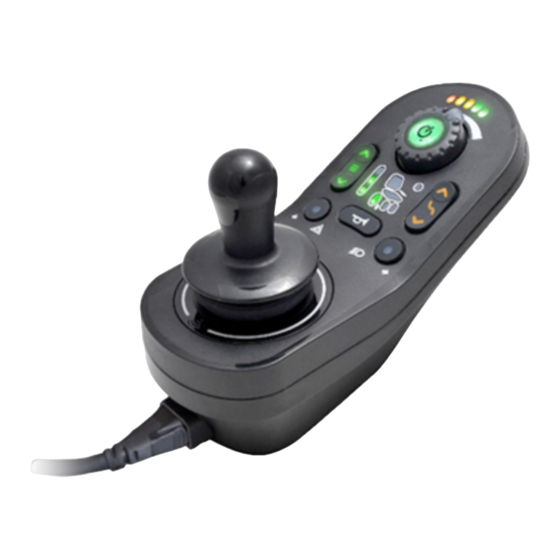
Components 2.2 User interface DLX-REM110 2.3 User interface DLX-REM211 A ON/OFF key/Status indicator B Battery gauge A ON/OFF key/Status indicator C Speed dial B Battery gauge D Horn C Speed dial E Joystick D Connectivity indicator E Seating mode selector F Drive/actuator status 1602969-B... -
Page 10: User Interface Dlx-Rem216
Invacare® LiNX G Horn A ON/OFF key/Status indicator H Joystick B Battery gauge I Drive mode indicator C Speed dial J Drive mode selector D Connectivity indicator E Seating mode selector 2.4 User interface DLX-REM216 F Drive/actuator status G Light and direction indicator right... -
Page 11: User Interface Dlx-Rem050 (Only As Attendant Dual Control)
Components 2.5 User interface DLX-REM050 (only as 2.6 The status indicator Attendant dual control) The status indicator is located inside the ON/OFF key. When the LiNX remote is not powered up, the status indicator is not lit. When the LiNX remote is powered up and there are no faults with the system, the status indicator lights green. -
Page 12: Labels On The Product
Invacare® LiNX Decreased driving range Recommendation to read the instruction manual before using Red and one amber LED on. the module. Consider charging batteries. READ INSTALLATION MANUAL BEFORE USE Very low driving range B IPx4 This is the enclosure's ingress Only red LED on. - Page 13 Components Product label containing: • Dynamic Controls' 'dynamic' logo The format, as shown above, is MYYnnnnnn, where: • Dynamic Controls' website address • M is for the month of manufacture, using the letters A to L (A = • Dynamic Controls’ part Jan, B = Feb, C = Mar, etc.), description •...
-
Page 14: Usage
Invacare® LiNX Switching on the remote 3 Usage Press the ON/OFF key A. 3.1 Switching the remote on and off If there is no fault with the system, the status indicator lights up green and the battery gauge displays the current battery status. -
Page 15: Controlling The Maximum Speed
Usage The joystick can also be used to wake up the system when in sleep mode, if this parameter has been enabled by the provider. Refer to 3.5 The sleep mode, page 17. 3.1.2 Controlling the maximum speed The speed dial allows you to limit the maximum speed of the mobility device (that is the speed when the joystick is fully deflected) to suit your preferences and environment. -
Page 16: The Horn
Invacare® LiNX 3.3 The horn 3.4 Locking/unlocking the remote Locking the remote Press the horn button A to sound the horn. The horn sounds for as long as the horn button is pressed. The horn button is also used for unlocking a locked system. Refer to 3.4 Locking/unlocking the remote, page 16. -
Page 17: The Sleep Mode
Usage Unlocking the remote and far right) until either the system is powered off, unlocked or the Sequence Timeout is reached. If an attendant dual control (DLX-REM50) is used, it is locked or unlocked, too. You can also lock and unlock the system via the attendant dual control. -
Page 18: Activate Seating Mode
Invacare® LiNX 3.6.1 Activate seating mode Powered seat tilt Powered recline Seat lifter Press the Activate seating mode key A. • The wheelchair changes to seating mode and the Left powered elevating legrest Drive/actuator status display C lights up amber. -
Page 19: The 10 Way Switch Module
None J Tilt down 3.6.4 Speed reduction and limit switches The mentioned speed reduction and limit switches do not apply to all Invacare wheelchair models. Unspecified Speed reduction If the lifter has been adjusted above a certain point, the drive 3.6.3 The 10 way switch module... -
Page 20: Activating The Drive Mode
Invacare® LiNX 3.7 Activating the drive mode Lifter seat lockout switch The drive electronics is equipped with a lifter seat lockout switch to prevent the lifter from rising up above a certain point when the seat tilt or backrest angle is adjusted above a certain point. The drive electronics stops automatically and the lifter symbol starts flashing. -
Page 21: Switching The Lights On And Off
3.9 Switching the hazard lights on and off With the Drive mode selector key you can choose between three different drive modes, that are configured by Invacare and can be fitted to your needs and requests by the provider. 3.8 Switching the lights on and off If you drive outside, turn on the lights under bad visibly conditions or darkness. -
Page 22: Switching The Direction Indicators On And Off
Invacare® LiNX 3.10 Switching the direction indicators on and 3.11 Charging the batteries Plug the battery charger into the remote’s charger socket A. If the remote is powered on, the battery gauge indicates the system is connected to the charger by cycling between a left-to-right chase... -
Page 23: Battery Alarms
Usage Only one red LED on and flashing. Battery charge state 4 Switch the wheelchair off. Red, amber and one green LED on. Charge the batteries immediately. Fully charged 3.12 Connecting the remote Green, green, amber, amber and red LEDs CAUTION! Risk of unintended stops If the plug of the remote cable is broken, the remote... -
Page 24: Attendant Dual Control
Remote-in-charge indication Before using the Attendant dual control for the first time, you should familiarize well with its operation Invacare Remote-in-charge Remote-not-in-charge recommends to test the behavior of the Attendant dual All indicators, including the The battery gauge is switched control without an occupant to avoid injury. - Page 25 Usage If one of the remotes in a dual system is faulty, the system can be driven with the other remote. If, however, the ON/OFF key on the remote-in-charge has a fault, the system does not operate. If one of the remotes is disconnected from the system when it is powered down, the remaining remote displays an error (refer to Flash code 2 in chapter 4.1.1 Error codes and diagnosis codes, page 26) when the system is powered up again to indicate that it was...
-
Page 26: Troubleshooting
Invacare® LiNX intention is that one of the suggestions may help you clear the 4 Troubleshooting problem. If in doubt, contact your provider. 4.1 Error diagnosis Flash Error description Possible action code If the electronic system shows a fault, use the following fault-finding guide to locate the fault. -
Page 27: Oonapu ("Out Of Neutral At Power Up")
Troubleshooting Drive OONAPU warning Flash Error description Possible action code If the system is powered up (or comes out of an inhibit state) while the joystick is not in the center position, a Drive OONAPU warning • Right magnetic brake Check cables and is displayed. -
Page 28: Drive Inhibit Indication
Invacare® LiNX 4.3 Drive inhibit indication • the status indicator flashes red (Flash code 2, refer to 4.1.1 Error codes and diagnosis codes, page 26), • the red LED on the battery gauge flashes, • the horn sounds once every ten seconds. -
Page 29: Technical Data
Technical data 5 Technical data 5.1 Technical specifications Mechanical specifications Permissible operating, storage and humidity conditions • Temperature range for operation according to ISO 7176–9: –25° ... +50 °C • Recommended storage temperature: 15 °C • Temperature range for storage according to ISO 7176–9: –40°... - Page 30 Invacare® LiNX Electrical specifications Parameter Min. Nominal Max. Units • • • • Operating voltage (Vbatt) • • Idle current mA at 24V • • Quiescent current (power 0.23 mA at 24V off) 1602969-B...
- Page 31 www.invacarelinx.com...
- Page 32 Invacare Sales Companies Australia: Ireland: New Zealand: Canada: Invacare Australia PTY. Ltd. Invacare Canada LP Invacare Ireland Ltd, Invacare New Zealand Ltd 1 Lenton Place, North Rocks NSW 570 Matheson Blvd E. Unit 8 Unit 5 Seatown Business Campus 4 Westfield Place, Mt Wellington 1060...
Need help?
Do you have a question about the LiNX DLX-REM110 and is the answer not in the manual?
Questions and answers