Table of Contents
Advertisement
Advertisement
Table of Contents

Related Manuals for Invacare REM 24 SD


Summary of Contents for Invacare REM 24 SD
- Page 1 Invacare® REM 24 SD Remote Operating Instructions...
- Page 2 How can you get in touch with Invacare®? If you have any questions or need support, please contact your authorised Invacare® Dealer, who has the necessary know-how and equipment plus the special knowledge concerning your Invacare® product, and can offer you all-round satisfactory service. Should you wish to contact Invacare® directly, you can reach us in Europe at the following addresses and phone numbers.
- Page 3 +31 - (0) 318 - 69 57 57 Fax (Kundeservice): +47 - 22 57 95 01 Fax: +31 - (0) 318 - 69 57 58 Invacare® PORTUGAL Lda Invacare® AB Rua Senhora de Campanhã, 105 Fagerstagatan 9 4369-001 Porto 163 91 Spånga...
-
Page 4: Table Of Contents
Table of Contents Chapter Page The REM 24 SD Remote Layout of the remote .........................5 ON/OFF diode (status display) ....................8 Battery charger display......................8 Activating / deactivating the immobilizer................9 Using the Buddy buttons with the remote ................10 Controlling the wheelchair using the remote ...............11 1.6.1... -
Page 5: The Rem 24 Sd Remote
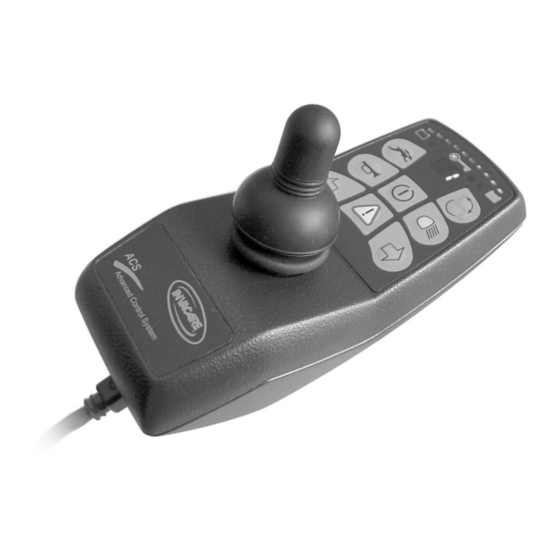
The REM 24 SD Remote Layout of the remote Upper side Controls Immobilizer "Activate / scroll through drive mode" button Horn Left-hand indicator Joystick "Activate / scroll through adjustment mode" button ON/OFF button Light Right-hand indicator 10) Hazard warning signal flasher... - Page 6 Upper side Displays 11) Battery charger display 12) Status display (in key symbol) 13) Drive mode display 14) Left-hand indicator display 15) Hazard warning signal flasher display 16) Light display 17) Right-hand indicator display...
-
Page 7: Rear Panel
Underside 1) Charger socket 2) Programming socket Rear panel Socket for Buddy button 1 (corresponds to "Activate / scroll through drive mode" button). Socket for Buddy button 2 (corresponds to "ON/OFF" button) Socket for Buddy button 3 (corresponds to "Activate / scroll through adjustment mode"... -
Page 8: On/Off Diode (Status Display)
ON/OFF diode (status display) INFORMATION The ON/OFF diode (in key symbol) also serves as status or error message display. For error codes please see chapter "Error codes and diagnostic codes" on page 18. Battery charger display • Battery charger display All diodes illuminated: Full range •... -
Page 9: Activating / Deactivating The Immobilizer
• Switch on the remote. • Use the end of the magnetic key (Invacare® Logo) to move over the sensor area (1) on the remote (key symbol). The horn will sound briefly once. The remote shuts down automatically. The immobilizer is activated. -
Page 10: Using The Buddy Buttons With The Remote
Using the Buddy buttons with the remote What is a Buddy button? A Buddy button is an additional sensing device that can be used to activate a remote function. The sockets for Buddy buttons are to be found at the rear of the remote. Socket 1 (corresponds to the ""Activate / scroll through drive mode""... -
Page 11: Controlling The Wheelchair Using The Remote
Can the electronic system programming be adapted? The electronic controller is programmed with standard values during manufacture. Your Invacare® dealer can carry out programming tailored to fit your requirements. Will the wheelchair not drive after switching on? Check the drive-away lock (see chapter "Activating / deactivating the immobilizer " on page... -
Page 12: How A Wheelchair With "Indirect Steering" Reacts To Joystick Movements
1.6.1 How a wheelchair with "Indirect Steering" reacts to joystick movements. "Indirect Steering" occurs by individually applying power to the drive wheels, and is found on wheelchairs with front, rear and middle wheel drive. Travel direction The further the joystick is moved in a particular direction, the more dynamically the wheelchair reacts. -
Page 13: How A Wheelchair With "Direct Steering" Reacts To Joystick Movements
1.6.2 How a wheelchair with "Direct Steering" reacts to joystick movements. Steering is operated by means of a servo motor. Travel direction The further the joystick is moved in a particular direction, the more dynamically the wheelchair reacts. Note: To brake quickly, simply let go of the joystick. It will then automatically return to the middle position. -
Page 14: Operating The Electric Adjustment Options
Operating the electric adjustment options Electric adjustment options, like electric legrests or an electric backrest, are operated by using the joystick. 1.7.1 Activating adjustment mode • Press the "activate / scroll through adjustment mode" button (A). The remote switches to the adjustment mode last used. The driving mode display (B) switches to the appropriate symbol (one of the symbols shown below). -
Page 15: Selecting And Operating The Adjustment Option
Information: When using the REM 24 SD remote it is not necessary – as on previous remote versions – to push the joystick forward in order to access the adjustment mode. It is sufficient to operate the adjustment mode button just once. -
Page 16: Changing Back To Driving Mode
1.7.3 Changing back to driving mode • Briefly press the "Activate / scroll through driving mode" button (A). The remote switches back to the driving mode last used. The driving mode display indicates the drive level (B). -
Page 17: Error Diagnosis
Error diagnosis In the event that the electronics should show signs of failure, please consult the following troubleshooting guide in order to locate the error. INFORMATION Before beginning with the diagnosis, please ensure that the drive electronics are switched on. If the status display is OFF: Please check whether the drive electronics are SWITCHED ON. -
Page 18: Error Codes And Diagnostic Codes
1.8.1 Error codes and diagnostic codes The drive electronics are capable of rectifying some errors automatically. In this case the status display will cease to flash. Please switch the remote on and off several times. Wait approx. 5 seconds each time before switching the remote on again. If this does not rectify the error, locate the error using the flash codes shown below. - Page 19 FLASH FAULT IMMEDIATE MEASURE FURTHER HELP CODE • Check plug-in connectors. • Error/brake error on Consult dealer. right motor. Connection loose/faulty or motor faulty. • Motors uncoupled Couple motors. Switch remote off and on again. • Check plug-in connectors. • Error/brake error on Consult dealer.
Need help?
Do you have a question about the REM 24 SD and is the answer not in the manual?
Questions and answers