Table of Contents
Advertisement
Advertisement
Table of Contents

Related Manuals for IFM Electronic CR2532


Summary of Contents for IFM Electronic CR2532
- Page 1 Installation instructions SmartController XL CR2532...
-
Page 2: Table Of Contents
SmartController XL CR2532 Contents 1 Preliminary note � � � � � � � � � � � � � � � � � � � � � � � � � � � � � � � � � � � � � � � � � � � � � � � � � 4 1�1 Symbols used�... - Page 3 SmartController XL CR2532 9 Approvals/standards � � � � � � � � � � � � � � � � � � � � � � � � � � � � � � � � � � � � � � � � � � � � � 27 This document is the original instructions�...
-
Page 4: Preliminary Note
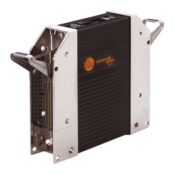
SmartController XL CR2532 1 Preliminary note This document applies to devices of the type "SmartController XL" (art� no�: CR2532)� These instructions are part of the device� This document is intended for specialists� These specialists are people who are qualified by their appropriate training and their experience to see risks and to avoid possible hazards that may be caused during operation or maintenance of the device�... -
Page 5: Safety Instructions
SmartController XL CR2532 2 Safety instructions 2.1 General These instructions are part of the device� They contain texts and figures concerning the correct handling of the device and must be read before installation or use� Observe the operating instructions� Non-observance of the instructions, operation which is not in accordance with use as prescribed below, wrong installation or incorrect handling can seriously affect the safety of operators and machinery�... -
Page 6: 2�5 Tampering With The Device
SmartController XL CR2532 2.5 Tampering with the device In case of malfunctions or uncertainties please contact the manufacturer� Tampering with the device can seriously affect the safety of operators and machinery� This is not permitted and leads to the exclusion of any liability and warranty claims�... -
Page 7: Installation
SmartController XL CR2532 4 Installation 4.1 Fastening ► Fix the controller to a flat surface using 4 M5 screws� Screw material: steel or stainless steel Tightening torque: 8 ±2 NOTE Use screws with a low head to avoid that the connector is damaged when placed and locked�... -
Page 8: 4�3 Mounting Surface
SmartController XL CR2532 4.3 Mounting surface NOTE The housing must not be exposed to any torsional forces or mechanical stress� ► Use compensating elements if there is no flat mounting surface available� Mounting surface 4.4 Heat dissipation ► Ensure sufficient heat dissipation as the internal heating of the electronics is conducted away via the housing�... -
Page 9: Electrical Connection
SmartController XL CR2532 5 Electrical connection 5.1 Wiring Wiring (→ 7 Technical data) Only connect the connector pins as shown in the pin layout� Unspecified connector pins remain unconnected� ► Connect all indicated supply cables and GND terminals (St and Ex connection side)�... -
Page 10: 5�3 Fuses
SmartController XL CR2532 5.3 Fuses ► The individual electric circuits must be protected in order to protect the whole system� Connection side Description Potential Pin no. Fuse St (Standard) Supply voltage sensors/module St-10 ≤ 2 A time-lag Supply voltage output group 1 St-19 ≤... -
Page 11: 5�5 Frequency And Analogue Inputs
SmartController XL CR2532 If a prewired connection cable is used, remove the cores with unused signal inputs and outputs� Unused cores, in particular core loops, lead to interference coupling that can influence the connected controller� 5.5 Frequency and analogue inputs ►... -
Page 12: 5�7 Can Wiring St/Ex Side
SmartController XL CR2532 5.7 CAN wiring St/Ex side 5.7.1 Point-to-point wiring CAN n CAN 2 60 Ω 1� Standard side: CANn (interface selectable) 2� Extended side: CAN2 (with factory pre-configuration) 3� Terminating CAN resistor in the cable 5.7.2 Open CANopen network... -
Page 13: Set-Up
● SmartController XL system manual (alternatively as online help) The manuals can be downloaded from the internet: www.ifm.com → Data sheet search → CR2532 → More information CODESYS and SmartController XL online help: www.ifm.com → Service → Download → Systems for mobile machines*... -
Page 14: Technical Data
Freescale PowerPC, 50 MHz Note If not otherwise speci ed, the data apply to the St and Ex side. ifm electronic gmbh ● Friedrichstraße 1 ● 45128 Essen We reserve the right to make technical alterations without prior notice! CR2532 / page 1... - Page 15 Physical memory Flash: 1.5 Mbytes RAM: 592 kBytes Remanent memory: 2 Kbytes Memory allocation See system manual www.ifm.com → Data sheet search → CR2532 → More information Software/programming Programming system CODESYS version 2.3 (IEC 61131-3) Indicators Status LED LED red / LED green...
-
Page 16: 7�2 Test Standards And Regulations
10...500 Hz; 0.72 mm/10 g; 10 cycles/axis ISO 16750-3: 2007 Bumps 30 g/6 ms; 24,000 shocks ifm electronic gmbh ● Friedrichstraße 1 ● 45128 Essen We reserve the right to make technical alterations without prior notice! CR2532 / page 3 28.03.2014... -
Page 17: 7�3 St Side / Input Characteristics
Short circuit to GND / wire break Voltage on the pin when not ≤ 0.2 V connected ifm electronic gmbh ● Friedrichstraße 1 ● 45128 Essen We reserve the right to make technical alterations without prior notice! CR2532 / page 4 28.03.2014... - Page 18 Input frequency ≤ 30 kHz Switch-on level > 0.35...0.48 U Switch-off level < 0.29 U ifm electronic gmbh ● Friedrichstraße 1 ● 45128 Essen We reserve the right to make technical alterations without prior notice! CR2532 / page 5 28.03.2014...
-
Page 19: 7�4 St Side / Output Characteristics
Diagnosis short circuit none Digital output (B Switching voltage 8...32 V DC Switching current 0.02...2 A ifm electronic gmbh ● Friedrichstraße 1 ● 45128 Essen We reserve the right to make technical alterations without prior notice! CR2532 / page 6 28.03.2014... - Page 20 (valid for all outputs) Short-circuit strength to GND Switch-off of the outputs is carried out via the output driver ifm electronic gmbh ● Friedrichstraße 1 ● 45128 Essen We reserve the right to make technical alterations without prior notice! CR2532 / page 7...
-
Page 21: 7�5 Ex Side / Input Characteristics
Short circuit to GND / wire break Voltage on the pin when not ≤ 0.2 V connected ifm electronic gmbh ● Friedrichstraße 1 ● 45128 Essen We reserve the right to make technical alterations without prior notice! CR2532 / page 8 28.03.2014... - Page 22 Input frequency ≤ 30 kHz Switch-on level > 0.35...0.48 U Switch-off level < 0.29 U ifm electronic gmbh ● Friedrichstraße 1 ● 45128 Essen We reserve the right to make technical alterations without prior notice! CR2532 / page 9 28.03.2014...
-
Page 23: 7�6 Ex Side / Output Characteristics
Diagnosis short circuit none Digital output (B Switching voltage 8...32 V DC Switching current 0.02...2 A ifm electronic gmbh ● Friedrichstraße 1 ● 45128 Essen We reserve the right to make technical alterations without prior notice! CR2532 / page 10 28.03.2014... - Page 24 (valid for all outputs) Short-circuit strength to GND Switch-off of the outputs is carried out via the output driver ifm electronic gmbh ● Friedrichstraße 1 ● 45128 Essen We reserve the right to make technical alterations without prior notice! CR2532 / page 11...
-
Page 25: 7�7 St Side / Wiring
Pulse width modulation Resistor input Supply sensors/module Supply output group 1 Supply output group 2 ifm electronic gmbh ● Friedrichstraße 1 ● 45128 Essen We reserve the right to make technical alterations without prior notice! CR2532 / page 12 28.03.2014... -
Page 26: 7�8 Ex Side / Wiring
Pulse width modulation Resistor input Supply sensors/module Supply output group 1 Supply output group 2 ifm electronic gmbh ● Friedrichstraße 1 ● 45128 Essen We reserve the right to make technical alterations without prior notice! CR2532 / page 13 28.03.2014... -
Page 27: Maintenance, Repair And Disposal
► Dispose of the device in accordance with the national environmental regulations� 9 Approvals/standards Test standards and regulations (→ 7 Technical data) The EC declaration of conformity and approvals can be found at: www.ifm.com → Data sheet search → CR2532 → Approvals...
Need help?
Do you have a question about the CR2532 and is the answer not in the manual?
Questions and answers