Table of Contents
Advertisement
Advertisement
Table of Contents

Related Manuals for IFM Electronic ECOMAT100 CR2500


Summary of Contents for IFM Electronic ECOMAT100 CR2500
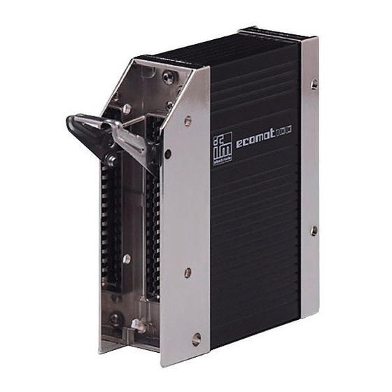
- Page 1 Installation instructions SmartController CR2500...
-
Page 2: Table Of Contents
SmartController CR2500 Contents 1 Preliminary note � � � � � � � � � � � � � � � � � � � � � � � � � � � � � � � � � � � � � � � � � � � � � � � � � 3 1�1 Symbols used�... -
Page 3: Preliminary Note
SmartController CR2500 1 Preliminary note This document applies to devices of the type "SmartController" (art� no�: CR2500)� These instructions are part of the device� This document is intended for specialists� These specialists are people who are qualified by their appropriate training and their experience to see risks and to avoid possible hazards that may be caused during operation or maintenance of the device�... -
Page 4: Safety Instructions
SmartController CR2500 2 Safety instructions 2.1 General These instructions are part of the device� They contain texts and figures concerning the correct handling of the device and must be read before installation or use� Observe the operating instructions� Non-observance of the instructions, operation which is not in accordance with use as prescribed below, wrong installation or incorrect handling can seriously affect the safety of operators and machinery�... -
Page 5: 2�5 Tampering With The Device
SmartController CR2500 2.5 Tampering with the device In case of malfunctions or uncertainties please contact the manufacturer� Tampering with the device can seriously affect the safety of operators and machinery� This is not permitted and leads to the exclusion of any liability and warranty claims�... -
Page 6: Installation
SmartController CR2500 4 Installation 4.1 Fastening ► Fix the controller to a flat surface using 4 M5 screws� Screw material: steel or stainless steel Tightening torque: 8 ±2 NOTE Use screws with a low head to avoid that the connector is damaged when placed and locked�... -
Page 7: 4�3 Mounting Surface
SmartController CR2500 4.3 Mounting surface NOTE The housing must not be exposed to any torsional forces or mechanical stress� ► Use compensating elements if there is no flat mounting surface available� Mounting surface 4.4 Heat dissipation ► Ensure sufficient heat dissipation as the internal heating of the electronics is conducted away via the housing�... -
Page 8: Electrical Connection
SmartController CR2500 5 Electrical connection 5.1 Wiring Wiring (→ 7 Technical data) Only connect the connector pins as shown in the pin layout� Unspecified connector pins remain unconnected� ► Connect all indicated supply cables and GND terminals� 5.2 Ground connection To ensure the protection of the device against electrical interference, the housing must be connected to GND (e�g�... -
Page 9: 5�5 Frequency And Analogue Inputs
SmartController CR2500 ► Connect supply and ground cables to the controller and the sensors/actuators via the respective common star point� If a prewired connection cable is used, remove the cores with unused signal inputs and outputs� Unused cores, in particular core loops, lead to interference coupling that can influence the connected controller�... -
Page 10: Technical Data
(max. 2 participants); master/slave connection Protocol predefined ifm protocol (INTELHEX) Node ID (default) hex 20 (= dec. 32) ifm electronic gmbh • Friedrichstraße 1 • 45128 Essen We reserve the right to make technical alterations without prior notice. CR2500 / page 1 21.05.2014... - Page 11 05, PC D-Sub (9 pins) "TEST" input programming mode 10...32 V DC (VBB operating mode open ifm electronic gmbh • Friedrichstraße 1 • 45128 Essen We reserve the right to make technical alterations without prior notice. CR2500 / page 2 21.05.2014...
-
Page 12: 7�2 Characteristics Of The Inputs/Outputs
. For the "RUN" mode the input must not be connected. input resistance 12 kΩ ifm electronic gmbh • Friedrichstraße 1 • 45128 Essen We reserve the right to make technical alterations without prior notice. CR2500 / page 3 21.05.2014... -
Page 13: 7�3 Test Standards And Regulations
(immunity with 100 V/m) Railway specification to BN 411 002 (DIN EN 50155 part 12.2: issue 03/2008) ifm electronic gmbh • Friedrichstraße 1 • 45128 Essen We reserve the right to make technical alterations without prior notice. CR2500 / page 4... -
Page 14: 7�4 Wiring
= supply voltage sensors/module CYL = inputs for time period measurement %QX0.xx = IEC address for binary output ifm electronic gmbh • Friedrichstraße 1 • 45128 Essen We reserve the right to make technical alterations without prior notice. CR2500 / page 5... -
Page 15: Maintenance, Repair And Disposal
SmartController CR2500 8 Maintenance, repair and disposal The unit is maintenance-free� ► Do not open the housing as the device does not contain any components which can be repaired by the user� The device must only be repaired by the manufacturer�...
Need help?
Do you have a question about the ECOMAT100 CR2500 and is the answer not in the manual?
Questions and answers