
Related Manuals for Invertek Drives OPT-2-ETHEG-IN

Summary of Contents for Invertek Drives OPT-2-ETHEG-IN
- Page 1 OPT-2-ETHEG-IN Ethernet IP Interface Installation and Operating Instructions Installation & Operating Instructions...
-
Page 2: Table Of Contents
Process Data Exchange ..................................12 6.5. Process Data PDI ....................................12 6.6. Process Data PDO ....................................13 6.7. OPT-2-ETHEG-IN Web Server ................................. 15 6.8. Drive parameter access ..................................17 6.9. Working with Rockwell Automation RSLogix5000 ..........................18 Technical Data .............................. 19 7.1. - Page 3 User Guide Revision 1.00 Invertek Drives Ltd adopts a policy of continuous improvement and whilst every effort has been made to provide accurate and up to date information, the information contained in this User Guide should be used for guidance purposes only and does not form the part of any contract.
-
Page 4: Introduction
Ensure that all terminals are tightened to the appropriate torque setting Do not attempt to carry out any repair of the Optidrive. In the case of suspected fault or malfunction, contact your local Invertek Drives Sales Partner for further assistance. www.invertekdrives.com... -
Page 5: General Information
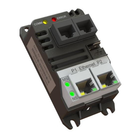
Module Status LED Network Status LED Ethernet Port P1 2.2. Labelling The OPT-2-ETHEG-IN has two labels, as shown below. Top Label : Provides the MAC ID and PR ID Data for the module Side Label : Provides, the model code and serial number data 2.3. -
Page 6: Power Up Sequence
Optidrive ODP-2ETHEG-IN User Guide Revisions 1.00 Network Status Indicator State Indication Steady Off Not powered, no IP address Steady Green Online, one or more connections active Flashing Green Online, no connections active Flashing Red Connection timeout Steady Red Duplicate IP Flashing Green and Red Self-test Module Status Indicator... -
Page 7: Mechanical Installation
Optidrive ODP-2ETHEG-IN User Guide Revisions 1.00 3. Mechanical Installation 3.1. Before Installation Carefully unpack the unit and check for any signs of damage. Notify the shipper immediately if any exist. To prevent accidental damage always store the unit in its original box until required. ... -
Page 8: Electrical Installation
Optidrive E3 Optidrive P2 Optidrive Eco The unit connects via an RJ45 cable, which also supplies the power to the OPT-2-ETHEG-IN from the 24 Volt output of the Optidrive. 4.2. Connection Diagram Optional Drive Keypad RJ45 Cable OPT-2-OPORT-IN... -
Page 9: Drive Parameter Settings
Optidrive ODP-2ETHEG-IN User Guide Revisions 1.00 5. Drive Parameter Settings 5.1. Overview The OPT-2-ETHEG-IN connects to the Optidrive Modbus interface. The default settings for this interface, for both the drive and the OPT-2- ETHEG-IN are:- Drive Address 1 ... - Page 10 Optidrive ODP-2ETHEG-IN User Guide Revisions 1.00 5.2.2. Optidrive P2 / Optidrive Eco The following parameters are used to configure the communication interface of the Optidrive P2 or Eco. Refer to the drive user guide for specific details of the functions of other parameters. Parameter Name Minimum Maximum...
-
Page 11: Operation
Drive control can be achieved via Class1 connections to the Assembly Object (0x04). The controller must implement the forward open request to the OPT-2-ETHEG-IN Port 3, address 1. For Drive specific allocation refer to Drive Manual and/or Ethernet/IP EDS file. -
Page 12: Process Data Exchange
Optidrive ODP-2ETHEG-IN User Guide Revisions 1.00 6.4. Process Data Exchange All Optidrives support a 4 word input, 4 word output process data exchange to allow control and monitoring of the drive. The functions and overview of each word are described below. 6.4.1. -
Page 13: Process Data Pdo
Optidrive ODP-2ETHEG-IN User Guide Revisions 1.00 6.6. Process Data PDO PDO data is returned from the drive to the master PLC. The available data for each word is described below. 6.6.1. PDO Word 1: Drive Status Word The function of PDO Word 1 is fixed for all drive models, and returns the drive Status Word. The individual bits within the drive status word indicates the status of the drive as follows. - Page 14 Optidrive ODP-2ETHEG-IN User Guide Revisions 1.00 6.6.3. PDO Word 2: Output Frequency The function of PDO Word 2 is fixed for all drive models, and returns the drive output frequency in Hz with one decimal place, e.g. returned value = 123, output frequency = 12.3Hz. 6.6.4.
-
Page 15: Opt-2-Etheg-In Web Server
Optidrive ODP-2ETHEG-IN User Guide Revisions 1.00 6.7. OPT-2-ETHEG-IN Web Server The OPT-2-ETHEG-IN web server interface can be accessed at via the IP address or host name. Default IP address : 192.168.1.254 Hostname : OPCxxxxxxxxxx, where xxxxxxxxxx = ‘PR ID’ value shown on the top product label as described in section 2.2 Both of the above values can be modified via the Web Server or Ethernet/IP Class 0xF4. - Page 16 Module will reboot if data is valid, otherwise an error status will be displayed: Status State Indication ‘Data Submitted...‘ Data has been submitted to OPT-2-ETHEG-IN, awaiting reply ‘Data Read/Write Error’ An error occurred, data was not stored ‘Resource Busy’ Another operation was accessing the required data for example a Ethernet/IP Class 0xF5 service ‘Invalid request - Data Validation Error’...
-
Page 17: Drive Parameter Access
6.8.1. Overview The OPT-2-ETHEG-IN is a Modbus translator device. This means that all data accessible from the drives Modbus RTU interface may also be accessed via the Ethernet/IP interface. For details of the relevant Modbus registers available for each drive, refer to the drive documentation. -
Page 18: Working With Rockwell Automation Rslogix5000
Press ‘Next’ and allow installation to complete At present only the OPT-2-ETHEG-IN EDS file is required. Individual Optidrive EDS files may be provided for mapping details, but are not currently supported by RSLogix5000 and therefore should not be loaded using the ‘EDS Hardware Installation Tool’... -
Page 19: Technical Data
Optidrive ODP-2ETHEG-IN User Guide Revisions 1.00 7. Technical Data 7.1. Environmental Ambient Temperature Storage and Transportation -40 … 60ᵒC / -40 … 140ᵒF Operating -10 … 50ᵒC / 14 … 122ᵒF UL Approved 40 … 50ᵒC / 104 … 122ᵒF Without UL approval Altitude Operating =<1000m... - Page 20 Optidrive ODP-2ETHEG-IN User Guide Revisions 1.00 82-EIPMN-IN_V1.00 www.invertekdrives.com...
Need help?
Do you have a question about the OPT-2-ETHEG-IN and is the answer not in the manual?
Questions and answers