Table of Contents

Related Manuals for Invertek Drives ODV-3-340240-3F12-MN


Summary of Contents for Invertek Drives ODV-3-340240-3F12-MN
- Page 1 Ethernet IP Interface OPT-2-ETHEG-IN Introduction COMM ERROR General Information Mechanical Installation Electrical Installation Drive Parameter P1 Ethernet P2 Settings Operation Technical Data...
-
Page 2: Table Of Contents
1. Introduction ........1. - Page 3 User Guide Revision 1.10 Invertek Drives Ltd adopts a policy of continuous improvement and whilst every effort has been made to provide accurate and up to date information, the information contained in this User Guide should be used for guidance purposes only and does not form the part of any contract.
-
Page 4: Introduction
Ensure that all terminals are tightened to the appropriate torque setting. Do not attempt to carry out any repair of the Optidrive. In the case of suspected fault or malfunction, contact your local Invertek Drives Sales Partner for further assistance. -
Page 5: General Information
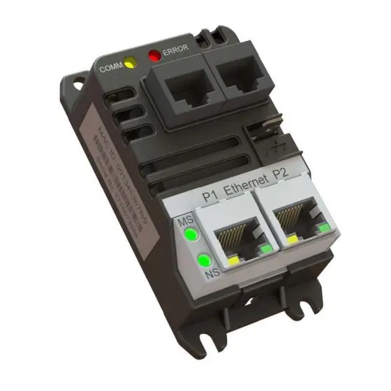
2. General Information 2.1. Overview COMM LED ERROR LED Indicator Indicator COMM ERROR Serial Serial Port 1 Port 2 Ground P1 Ethernet P2 Module Status LED Ethernet Network Port 2 Status LED Ethernet Port 1 2.2. Labelling The OPT-2-ETHEG-IN has two labels, as shown below. Top Label Top Label: Provides the MAC ID and PR ID Data for the module. -
Page 6: Connection Ports
2.3. Connection Ports The interface connects to the Ethernet IP network and slave drive via the built in connection ports. Port Function Ethernet Port 1 Ethernet Port 2 IOIOI 1 RJ45 Drive Data Connection IOIOI 2 RJ45 Aux equipment Connection 2.4. -
Page 7: Power Up Sequence
Link Activity LEDs (P1/P2) State Indication Steady Yellow 100Mbps link active P1 Speed Steady Off 10Mbps or No link Steady Green Valid Link P1 Link Activity Steady Off No Link Flash TX/RX Steady Yellow 100Mbps link active P2 Speed Steady Off 10Mbps or No link Steady Green Valid Link... -
Page 8: Mechanical Installation
3. Mechanical Installation 3.1. Before Installation C arefully unpack the unit and check for any signs of damage. Notify the shipper immediately if any exist. T o prevent accidental damage always store the unit in its original box until required. S torage should be clean and dry and within the temperature range -40°C to +60°C. -
Page 9: Electrical Installation
4. Electrical Installation 4.1. Overview The OPT-2-ETHEG-IN is intended for operation with one of the following Invertek Drives‘ products: O ptidrive E3 O ptidrive P2 O ptidrive Eco. The unit connects via an RJ45 cable, which also supplies the power to the OPT-2-ETHEG-IN from the 24 Volt output of the Optidrive. -
Page 10: Drive Parameter Settings
5. Drive Parameter Settings 5.1. Overview The OPT-2-ETHEG-IN connects to the Optidrive Modbus interface. The default settings for this interface, for both the drive and the OPT-2-ETHEG-IN are: D rive Address 1 1 15200 kbps baud rate 1 Start Bit 8 Data Bits 1 Stop Bit... - Page 11 5.2.2. Optidrive P2 / Optidrive Eco The following parameters are used to configure the communication interface of the Optidrive E3. Refer to the drive user guide for specific details of the functions of other parameters. Par. Description Minimum Maximum Default Units P-12 Primary Command Source...
- Page 12 Par. Description Minimum Maximum Default Units P5-14 Fieldbus Process Data Input Word 3 Select Torque Limit/Reference This option must be selected if the drive output torque limit / setpoint are to be controlled from the fieldbus. This also requires setting P4-06 = 3. User PID Reference This option allows the setpoint to the PID controller to be received from the Fieldbus.
-
Page 13: Operation
6. Operation 6.1. Overview Cyclic control and monitoring of the drive is achieved by a Class 1 connection to the mapped Modbus PDI and PDO parameters.This can be achieved using one of the following methods. 6.2. Configuration The OPT-2-ETHEG-IN supports the following Ethernet/IP classes: 0 x01 Identity 0 x02 Message Router 0 x06 Connection manager... -
Page 14: Process Data Exchange
6.3.2. Method 2: Class 1 connection via OPC-2-ETHIG-IN ‘Forward Open Assembly’ object The OPC-2-ETHIG-IN provides the Vendor Class ‘Forward Open Assembly (0x0300)’ which negates the need for the control to provide the forward open mapping. For Drive specific allocation refer to Drive Manual and/or Ethernet/IP EDS file. For Drive specific read/write limitations refer to Drive Manual and/or Ethernet/IP EDS file. -
Page 15: Process Data Pdi
6.5. Process Data PDI 6.5.1. PDI Word 1: Drive Control Word The drive control word can be used to control the drive as follows: Port Function 0: Stop 1: Run 0: Normal Operation 1: Fast Stop 0: No Function 1: Fault Reset Request 0: Normal Operation 1: Coast Stop No function... - Page 16 Function 0: Drive Disabled (Stopped) ✔ ✔ ✔ 1: Drive Enabled (Running) 0: Drive Healthy ✔ ✔ ✔ 1: Drive Tripped 0: Auto ✔ 1: Hand 0: Drive Ready (STO Input Closed) ✔ ✔ 1: Drive Inhibit (STO Input Option 0: Maintenance Time Not Reached ✔...
- Page 17 Ambient temperature too high. Maximum torque limit exceeded. Output torque too low. Drive output fault. Internal STO circuit error. Encoder feedback fault. Speed error. Encoder feedback fault. Encoder feedback fault. Encoder feedback fault. Autotune failed. Input phase sequence incorrect. Output (Motor) phase loss. Modbus comms fault.
-
Page 18: Opt-2-Etheg-In Web Server
6.6.11. User Register 1 / User Register 2 For P2 and Eco drives, which have internal function block programming capability, data may be read from the User Registers. This allows control functions to be achieved within the drive by linking to the Group 9 parameters. The values may also be used within the function block program. - Page 19 6.7.3. Network Settings The present network settings for the interface are displayed. This data may be changed by the user. ‘Configured’ indicated the values currently stored within the module. ‘Working Values’ indicate the values currently in use (if not yet edited), or the values to be applied. To commit values press ‘Set’. Module will reboot if data is valid, otherwise an error status will be displayed: Status State...
-
Page 20: Drive Parameter Access
6.7.4. Drive Identity Data is read from the Drive. If the Drive does not support this functionality then the following data is required: V endor Name: ‘Unknown Modbus Device’ P roduct Code: Empty V ersion Number: Empty. 6.8. -
Page 21: Working With Rockwell Automation Rslogix5000
6.9. Working with Rockwell Automation RSLogix5000 This section describes how to configure a Rockwell Automation RSLogix5000 project to connect to an Optidrive via the OPT-2-ETHEG-IN. NOTE At present Rockwell Automation RSLogix5000 does fully not support the CIP Modbus Translator specification, due to this Optidrives will only appear within the RSLogix5000 Project as an OPT-2-ETHEG-IN CIP Modbus Translator Device. -
Page 22: Technical Data
7. Technical Data 7.1. Environmental Ambient Temperature Storage and Transportation -40 … 60°C / -40 … 140°F Operating -10 … 50°C / 14 … 122°F UL approved 40 … 50°C / 104 … 122°F Without UL approval Maximum Altitude Operating =<1000m UL approved =<4000m... - Page 23 www.invertekdrives.com Version 1.10 | Optidrive ODP-2ETHEG-IN | 23...
- Page 24 Ñ82-EIPMN-IN_V1.10bÓ 82-EIPMN-IN_V1. 1 0 Invertek Drives Ltd. Offa's Dyke Business Park, Welshpool, Powys SY21 8JF United Kingdom Tel: +44 (0)1938 556868 Fax: +44 (0)1938 556869 www.invertekdrives.com...
Need help?
Do you have a question about the ODV-3-340240-3F12-MN and is the answer not in the manual?
Questions and answers