Table of Contents
Advertisement
Quick Links
C800 Cylindrical Lever Set
Installation Instructions
Tools required
#2 Cross drive screwdriver
Flathead screwdriver
5
4
3
2
1
15
1.3
Install lock assembly
Fig 3
Adjust for door thickness
1.3.3 Rotate outside rose assembly
to adjust for proper door
NOTE: Lock comes adjusted for
thickness.
1-3/4" door from the factory.
1.3.4 Realign thru-bolt retainer with
1.3.1 Align so center of chassis is in
outside rose.
line with center of latch.
1.3.2 Slightly separate thru-bolt
retainer from outside rose
assembly.
Center of
latch
Thru-bolt
retainer
Chassis
Outside rose
assembly
76013497
02/18
9
8
7
6
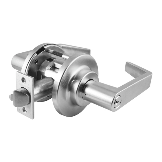
PART LIST
1- IC CORE
2- OUTSIDE IC LEVER
3- OUTSIDE ROSE
4- OUTSIDE ROSE INSERT
5- THRU BOLT RETAINER
6- CHASSIS
7- INSIDE ROSE
8- 10-32 X 1-1/2" SCREWS (X2)
13
9- INSIDE ROSE
10- LEVER INSERT
12
11- INSIDE LEVER
12- LATCH
13- 8-32 X 3/4" COMBO
14- OUTSIDE CONVENTIONAL
15- CONVENTIONAL CYLINDER
14
Install chassis
1.3.5 Slide lock assembly into face of door.
Be sure to engage the inner latch
mechanism of the chassis with the back of
the latch as shown.
Latch or
latch bolt
Chassis
with
extension
1 Cylindrical lock installation
1.1
Install latch
Fig 1
1.1.1
Place latch into door edge.
Orient such that the beveled edge of latch
11
faces door jamb.
10
1.1.2
Secure with two 8-32 x 3/4" combo screws.
MOUNTING PLATE
SCREWS (2)
CYLINDER LEVER
Beveled
edge
1.4
1.5
Install inside rose insert
Fig 4
Fig 5
1.4.1 Hold lock
1.4.3 Ensure mounting
1.5.1
assembly in
plate is aligned
place.
with holes in door.
•
1.4.2 Thread inside
1.4.4 Secure mounting
rose mounting
plate to chassis
onto chassis
using two
until snug
10-32 x 1-1/2"
against door.
screws.
Spanner
wrench
Inside
lever
NOTE: Be sure lever insert
is inserted into inside lever
prior to installation.
1.5.2
Rose
mounting
plate
1.2
Optional extension instructions
Fig 2
Latch bolt
extension
1.2.1
Connect latch bolt
extension to latch
bolt.
1.2.2
Slide sleeve over
top of both,
extension and
latch bolt.
1.2.3
Extension can be
oriented in either
direction.
Latch bolt with
extension & sleeve
1.6
Install rose
Fig 6
Push inside rose onto
1.6.1
inside rose mounting
plate.
Orientation: rose notch
faces downward.
Rose
notch
location
Inside
rose
3
Inside
rose
Spindle
mounting
plate
Push inside lever
onto spindle until
it clicks into place.
Latch bolt
sleeve
Install strikes
Insert strike as shown, and secure with
two 12-24 x 1" combo screws.
STRIKE PART LIST
1 - STRIKE PLATE
2 - DUST BOX
3 - 12-24 X 1" COMBO-SCREWS
Non-wood doors
2
1
www.dormakaba.us
Advertisement
Table of Contents

Subscribe to Our Youtube Channel
Related Manuals for Dormakaba C800


Summary of Contents for Dormakaba C800
- Page 1 C800 Cylindrical Lever Set Installation Instructions 1 Cylindrical lock installation Install latch Optional extension instructions Fig 1 Fig 2 Tools required Latch bolt #2 Cross drive screwdriver extension Flathead screwdriver 1.1.1 Place latch into door edge. Orient such that the beveled edge of latch faces door jamb.
- Page 2 45°. 10-32 x 1-1/2” insert #8 combo Press lever fully onto spindle until screws screws it clicks into place. Fig 10C Inside rose 5.10 Release key. Outside rose insert mounting Correct Incorrect mounting plate plate 76013497 02/18 www.dormakaba.us...
Need help?
Do you have a question about the C800 and is the answer not in the manual?
Questions and answers