Advertisement
Quick Links
Advertisement

Subscribe to Our Youtube Channel
Related Manuals for IDEC DD3S Series

Summary of Contents for IDEC DD3S Series
- Page 1 Display Units DD3S Series DD48 Series DD96 Series...
- Page 2 Display Units (Selection Guide) DD3S Series Shape Unit Type Binary Decimal/Hexadecimal/Extra Decimal Character Display 12.7 Display Part (mm) Notes: +, –, 1 7-segment The red and green colors of the Red LED Red or green LED Red LED, Green LED single color LEDs are different Red/green 2-color alternate LED from those of the 2-color...
- Page 3 Display Units (Selection Guide) DD48 DD96 Front Mount Rear Mount Binary Decimal Decimal 11.1 – (minus) 7-segment Red or green LED Red or green LED 7-segment Red LED 0 to 9 0 to 9 – (minus) Decimal point Decimal point —...
-
Page 4: Ordering Information
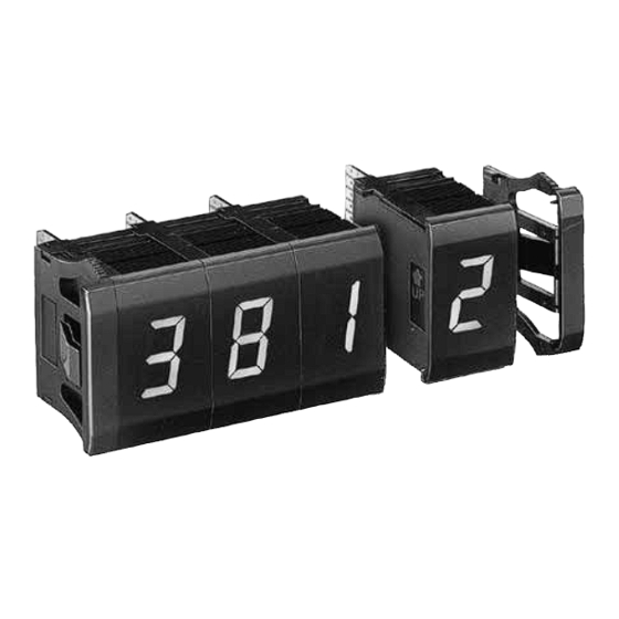
DD3S Display Units Series 7-segment digital display and 5 × 7 dot matrix character display units Super bright LED display and short body for up to 8 digits • Super bright LED for easy reading • Units can be combined together and installed into a panel cut-out. - Page 5 DD9Z-JE1C Type C Between live and dead parts : Coupling Spacer Right Side Black DD9Z-FG1R-B 1000V AC, 1 minute for IDEC DG Series Insulation Between live and dead parts : Left Side Black DD9Z-FG1L-B Digital Switches Resistance 100 MΩ min. (500V DC megger)
- Page 6 DD3S Display Units Series Terminal Connection Connection Diagram Terminal Arrangement Internal Input Circuit Standard Standard (Terminal No.) (Terminal No.) Power Regulating Circuit − – Latch Power Latch 12 to 24V DC – Standard Standard (Terminal No.) (Terminal No.) Power Regulating Circuit A ( 2 ) −...
- Page 7 DD3S Display Units Series External Wiring Binary/Decimal/Hexadecimal/Extra Decimal Display Units Positive Logic [Contact Input (Digital Switch)] [Transistor Input] Connector Terminal No. Vcc (+) Vcc (+) Vcc (+) (DMC-1) Data Data Data Power Power Power Input Input Input UP Making Side −...
- Page 8 DD3S Display Units Series Function Table Input Functions Binary Display Unit (Standard) 1, +, and – Inputs Data Input When the 1, +, or – input is set to level H for the positive Positive Logic Negative Logic logic or level L for the negative logic, the 1, +, or – display Display is turned on, respectively.
- Page 9 DD3S Display Units Series (Zero-suppress Unit) Leading zeros are suppressed using the RBI (No. 1) and RBO (No. 11) terminals. For other inputs, see the lower table on the preceding page. Decimal/Hexadecimal/Extra Decimal Input and Output Functions Data Input RBI Input Positive Logic Negative Logic Display...
- Page 10 DD3S Display Units Series Display Patterns of the Character Display Unit D7, D6, D5, D4 (High-bit data) Data Input 1: Level H Positive 0: Level L 0000 0001 0010 0011 0100 0101 0110 0111 1000 1001 1010 1011 1100 1101 1110 1111 Logic...
- Page 11 DD3S Display Units Series Dimensions & Panel Cut-out All dimensions in mm. Panel Cut-out Character Display Unit End Plate Binary Dec/Hex Panel Thickness 0.8 to 4 For Connector Wiring Display Unit Display Unit Spacer Unit For Use of Dynamic Mother Board DD9Z-FY1-8 3.5 min.
- Page 12 DD3S Display Units Series Static Mother Board (not applicable to zero-suppress) 4-digit: DD9Z-MB2-4 3-digit: DD9Z-MB2-3 Note: The DD3S housing can be secured to the mother board 2-digit: DD9Z-MB2-2 using screws. Recommended tightening torque is 0.35 N·m at the maximum. When no spacer is used, the tightening torque must not exceed 0.2 N·m.
- Page 13 19 20 Coupling Spacer Coupling Spacer for Right Side (DD9Z-FG1R-B) For using DD3S series Display Units and the IDEC DGAN/DGBN Coupling Spacer for right side series Digital Switches in combination, coupling spacers (two types: for right side and left side) are available.
- Page 14 Mother Board For Connection to Connector Header [Input Side Connector] DD9Z-JE1B Gray Cable MIL flat cable connector (with strain relief) Input Side IDEC’s JE1S-201 (with strain relief) Mother Board Connector Dimensions Applicable Connector Header IDEC’s JE1H-201 (Right Angle) IDEC’s JE1H-202 (Straight) 29.97...
-
Page 15: Wiring Diagrams
DD3S Display Units Series Wiring Diagrams Static Mother Board Connection (2 to 4 digits) Transistor Output A (10 ) OUT A0 B (10 ) OUT A1 C (10 ) OUT A2 D (10 ) OUT A3 A (10 ) OUT A4 B (10 ) OUT A5 C (10 ) - Page 16 DD3S Display Units Series Dynamic Connection (2 to 4 digits) Transistor Output Latch (10 ) OUT 0 Latch (10 ) OUT 1 Latch (10 ) OUT 2 Latch (10 ) OUT 3 OUT 4 OUT 5 OUT 6 OUT 7 COM (0V) −...
- Page 17 DD3S Display Units Series Latch Input [Binary/Decimal/Hex/Extra Decimal Display Units] [Character Display Unit] Latch Operation (Positive Logic) Latch Operation (Positive Logic) “1” “2” “3” “4” “5” “6” “7” “8” “9” “1” “2” “3” “4” “5” “6” “7” “8” “9” ( H ) ( L ) ( H ) Binary-...
-
Page 18: Panel Mounting
DD3S Display Units Series Unit Combination Instructions 1. When cleaning the surface of the filter and housing, use a soft Display units and end plates can be combined together by snap cloth. Do not use thinner or acid to clean the surface. fit. - Page 19 DD48 Display Units Series Modular units can be combined for up to 16 digits. • Super bright LED • Units can be combined together and installed into a panel cut-out by snap fit. • Binary and decimal display units are available. • Easy wiring and maintenance • LED display color: red or green • Decimal display units are available with zero suppression function.
- Page 20 DD48 Display Units Series Terminal Connection Connection Diagram Terminal Arrangement Internal Input Circuit (Name) (Terminal No.) (Name) (Terminal No.) Regulating Circuit Power Positive Logic (−) 24V DC 200 k Latch Data Input Latch (–) 12 k 200 k (Name) (Terminal No.) (Name) (Terminal No.) Negative Logic Power...
- Page 21 DD48 Display Units Series Function Table Binary Display Unit Data Input (H, L: Voltage Level) Input Functions Positive Logic Negative Logic Display – Input — Latch — Latch Blank or – display is selected. blank Latch Input — When the Latch input is set to level H for the positive logic ×...
- Page 22 DD48 Display Units Series Dimensions & Panel Cut-out All dimensions in mm. Binary Decimal Display Unit Spacer Unit Display Unit End Plate ( DD48-FY1-B ) ( DD48-W- Panel Thickness: 0.8 to 4 30N + 14 Display units can be combined for up to 16 digits. Note: When mounting more (Panel Cut-out) When combining 9 to 16 digits, it is recommended to use the long...
- Page 23 Note 1: When decimal point display inputs (DP1 to DP4) for decimal display Data Input Connector units are programmed by wiring on the mother board, do not use IDEC’s JE1H-302 terminals 7 to 10 of the data input connector. Note 2: For the decimal display units, the mother board is not printed-wired for the zero suppression function.
- Page 24 Side Decimal Marking For Connection to Connector Header [Input Side Connector] DD48-JE1B MIL flat cable connector (with strain relief) Cable Marking IDEC’s JE1S-301 (with strain relief) Mother Board Input Side Dimensions <Applicable Connector Header> Connector IDEC’s JE1H-301 (Right Angle) Marking 42.67...
- Page 25 DD48 Display Units Series Installation Installation of Mounting Clip When mounting more than 4-digits, install mounting clips from Unit Combination the behind and tighten them. Refer to the following figures for the number of clips and the mounting positions. Display units and end plates can be combined together by snap fit.
- Page 26 DD48 Display Units Series Latch Input Instructions 1. When cleaning the surface of the filter and housing, use a soft Latch Operation cloth. Do not use thinner or acid to clean the surface. 2. When the display unit is mounted in a panel cut-out, do not “1”...
- Page 27 DD96 Display Units Series Two mounting styles; front and rear mount. High visible large LEDs; character height 57 mm. • Modular units can be combined for up to 8-digits. • Super bright LED • Units can be combined together and installed into a panel cut-out by snap fit.
- Page 28 DD96 Display Units Series Terminal Connection Connection Diagram Terminal Arrangement (Connector) Bottom View (Name) (Terminal No.) (A-1) Power Regulating (B-1) 24V DC Circuit (A-8) (B-8) A(2 ) (A-2) (B-2) (B-1) (A-1) B(2 ) (A-3) Data (B-3) Input A(2 ) (B-2) (A-2) A(2 ) C(2 )
- Page 29 DD96 Display Units Series Dimensions & Panel Cut-out Front Mount Rear Mount End Plate (optional) Display Unit Panel Thickness: 0.8 to 4 4-ø3.3 Hole Approx. Approx. 41 72 × N N: No. of digits (8 digits maximum) (Panel Cut-out) 72N + 20.5 10 min.
- Page 30 DD96 Display Units Series Latch Input Connection to Terminals BI and BO Latch Operation [Ex. 1] “1” “2” “3” “4” “5” “6” “7” “8” “9” By connecting as shown below, 0 is displayed when input is 0000 and 25 is displayed when input is 0025, eliminating unnecessary 0s in upper digits.
- Page 31 Display Units...
- Page 32 Hsi-Chih District, 22101 New Taipei City, Taiwan Tel: +86-21-6135-1515 Mississauga, Ontario, L5L 4X7, Canada Tel: +886-2-2698-3929, Fax: +886-2-2698-3931 Fax: +86-21-6135-6225 / +86-21-6135-6226 Tel: +1-905-890-8561, Toll Free: (888) 317-IDEC (4332) E-mail: service@tw.idec.com E-mail: idecS@cn.idec.com Fax: +1-905-890-8562 IDEC IZUMI ASIA PTE. LTD.
Need help?
Do you have a question about the DD3S Series and is the answer not in the manual?
Questions and answers