Walchem W600 Series Instruction Manual
Metal finishing controller
Hide thumbs
Also See for W600 Series:
- Instruction manual (76 pages) ,
- Instruction manual (88 pages) ,
- Troubleshooting manual (10 pages)

Subscribe to Our Youtube Channel
Related Manuals for Walchem W600 Series


Summary of Contents for Walchem W600 Series
- Page 1 W600 Series Metal Finishing Controller Instruction Manual Five Boynton Road Hopping Brook Park Holliston, MA 01746 USA TEL: 508-429-1110 WEB: www.walchem.com...
- Page 2 WALCHEM and for the purposes disclosed in writing at the time of purchase, if any. WALCHEM’s liability under this warranty shall be limited to replacement or repair, F.O.B. Holliston, MA U.S.A.
-
Page 3: Table Of Contents
Contents INTRODUCTION ..............................1 SPECIFICATIONS..............................2 2.1 Measurement Performance ............................2 2.2 Electrical: Input/Output ............................3 2.3 Mechanical ................................5 2.4 Variables and their Limits ............................6 UNPACKING & INSTALLATION ...........................8 3.1 Unpacking the unit ..............................8 3.2 Mounting the electronic enclosure ..........................8 3.3 Immersible Copper Sensor Installation ........................9 3.4 Flow Through Copper Sensor/Sample Loop Installation ..................9 3.5 Flow Through Nickel Sensor/Sample Loop Installation ..................9 3.6 Other Sensor Installation ............................11... - Page 4 5.3.8 Relay, Manual Mode ........................... 58 5.3.9 Relay, Pulse Proportional Control Mode ....................59 5.3.10 Relay, PID Control Mode ..........................59 5.3.11 Relay, Dual Set Point Mode ........................62 5.3.12 Relay, Timer Control Mode ......................... 62 5.3.13 Relay, Probe Wash Control Mode ......................63 5.3.14 Relay, Spike Control Mode .........................
-
Page 5: 1.0 Introduction
An Ethernet option provides remote access to the controller’s programming via a PC connected directly, via a local area network, or via Walchem’s VTouch account management server. It also allows emailing of datalog files (in CSV format, compatible with spreadsheets like Excel) and alarms, to up to eight email addresses. -
Page 6: 2.0 Specifications
2.0 SPECIFICATIONS Measurement Performance Sensor Specs Copper Range 0.10 to 99 g/l (varies with the chemical being measured) 0.10 to 5.50 g/l typical for electroless copper Resolution 0.01 g/l Accuracy ± 0.01 g/l Nickel Range 0.10 to 25 g/l (varies with the chemical being measured) Resolution 0.01 g/l Accuracy... -
Page 7: Electrical: Input/Output
Electrodeless Conductivity (not available on the combination sensor/analog input card) OR Disinfection Amplified pH or ORP Requires a preamplified signal. Walchem WEL or WDS series recommended. ±5VDC power available for external preamps. Each sensor input card contains a temperature input... - Page 8 Temperature 100 or 1000 ohm RTD, 10K or 100K Thermistor (For Cu/Ni card, only 1000 ohm RTD) Analog (4-20 mA) Sensor Input (0, 1, 2-wire loop powered or self-powered transmitters supported 2 or 4 depending on model code): 3 or 4 –wire transmitters supported Each dual sensor input board has two channels Channel 1, 130 ohm input resistance Channel 2, 280 ohm input resistance...
-
Page 9: Mechanical
Agency Approvals: Safety UL 61010-1:2012 3rd Ed. CSA C22.2 No. 61010-1:2012 3rd Ed. IEC 61010-1:2010 3rd Ed. EN 61010-1:2010 3rd Ed. IEC 61326-1:2012 EN 61326-1:2013 Note: For EN61000-4-6, EN61000-4-3 the controller met performance criteria B. *Class A equipment: Equipment suitable for use in establishments other than domestic, and those directly connected to a low voltage (100-240 VAC) power supply network which supplies buildings used for domestic purposes. -
Page 10: Variables And Their Limits
Pressure vs. Temperature 24.1 20.7 17.2 pH/ORP 13.8 10.3 Cond HP Cond/Steel HP pH/ORP/Steel °F °C Variables and their Limits Sensor Input Settings Low Limit High Limit Calibration Offset (Copper or Nickel only) -10 g/l or oz/gal 10 g/l or oz/gal Stabilization Time (Copper or Nickel only) 0:00 minutes 59:59 minutes... - Page 11 Totalizer Alarm 0 vol. units 1,000,000 vol. units Set Flow Total 0 vol. units 1,000,000,000 vol. units Flow Alarm Delay 00:10 Minutes 59:59 Minutes Flow Alarm Clear 1 Contact 100,000 Contacts Dead Band Reprime Time 00:00 Minutes 59:59 Minutes Volume/Contact 0.001 ml 1,000.000 ml Smoothing Factor...
-
Page 12: 3.0 Unpacking & Installation
Inspect the contents of the carton. Please notify the carrier immediately if there are any signs of damage to the controller or its parts. Contact your distributor if any of the parts are missing. The carton should contain a W600 series controller and an instruction manual. -
Page 13: Immersible Copper Sensor Installation
Immersible Copper Sensor Installation The immersible copper sensor is designed for direct in-tank monitoring of electroless copper and microetch solutions. By monitoring the copper content directly in the solution, control lag and hydraulic problems are eliminated. The sensor is constructed such that a constant path length exists between the fiber optic light guides. The solution between the light guides absorbs light at specific wavelengths in proportion to the copper concentration. - Page 14 voltage wiring in conduit that is separated a minimum of 6 inches from low voltage DC signal lines (such as the sensor signal). The sample loop consists of a shut off valve, a cooling coil or plate, a sensor, an optional pH adapter assembly, a pump, or any combination thereof.
-
Page 15: Other Sensor Installation
If the desired control band is 0.20 g/L (± 0.10 g/L or 2.5%) and the bath is depleting at a rate of 1.25 g/L every 15 minutes (0.08333 g/L every minute), then Max. Lagtime = 0.20 g/L 0.60 minutes 4 x (0.08333 g/L /min) So, 0.60 minutes is the maximum time it should take for the solution to reach the sensor. - Page 16 Locate the sensors where an active sample of water is available and where the sensors can easily be removed for cleaning. Position the sensor such that air bubbles will not be trapped within the sensing area. Position the sensor where sediment or oil will not accumulate within the sensing area. In-Line Sensor Mounting In-line mounted sensors must be situated so that the tee is always full and the sensors are never subjected to a drop in water level resulting in dryness.
-
Page 17: Icon Definitions
Proper grounding of this product is required. Any attempt to bypass the grounding will compromise the safety of persons and property. Operating this product in a manner not specified by Walchem may impair the protection provided by the equip- ment. - Page 18 4-20 mA Outputs Power In Ethernet Sensor 1 Power Switch Digital Inputs Relays Relays Sensor 2 Figure 1 Conduit Wiring...
- Page 19 IMMERSIBLE SENSOR 20 FT (80 FT MAX.) POWER PLATING BATH CAUSTIC FORMAL- STABILIZER COPPER DEHYDE WCU WITH IMMERSIBLE SENSOR (TYPICAL ELECTROLESS COPPER APPLICATION) CONVEYORIZED SPRAY EQUIPMENT WASTE TREATMENT W A L C H E M 80 FT. MAX. METERING PUMPS POWER MANUAL CIRCULATING...
- Page 20 Figure 3 WNI with Flow through Sensor and Degasser (Typical Electroless Nickel Application)
- Page 21 Figure 4 WNI with Flow Through Sensor, without Degasser (Typical Electrodless Nickel Application)
- Page 22 Figure 5 Parts Identification...
- Page 23 POWER SWITCH FUSE Sensor 1 Sensor 2 Optional Temperature Cu/Ni Compensation TEMP– WHT/GRN TEMP– TEMP+ GRN/WHT TEMP+ IN– WHT/ORN IN– ORN/WHT –5V WHT/BLU –5V BLU/WHT WHT/BLU pH electrode ORN/WHT GRN/WHT BLU/WHT +2.5V WHT/GRN +2.5V SHIELD SHIELD Cu/Ni SHIELD USE TB3 #12 Shield to TB 3#12...
- Page 24 POWER SWITCH FUSE Sensor 1 Sensor 2 SENSOR INPUT CARD LABEL pH/ORP ECOND CCOND TEMP– WHT TEMP– TEMP– TEMP– TEMP+ TEMP+ TEMP+ TEMP+ GRN IN– R-SHLD BLACK RCV– Conductivity RCV+ Electrode SHIELD X-SHLD SHIELD SHIELD GRN WHT RED BLK –5V High Pressure XMT+ XMT–...
- Page 25 POWER SWITCH FUSE Sensor 1 Sensor 2 pH/ORP ECOND CCOND TEMP – BLK TEMP– TEMP– TEMP– TEMP+ TEMP+ TEMP+ TEMP + GRN R-SHLD (SHIELD) IN– R-SHLD RCV – BLK RCV– RCV + RED RCV+ X-SHLD (SHIELD) X-SHLD SHIELD SHIELD –5V XMT+ XMT + WHT XMT –...
- Page 26 POWER SWITCH FUSE Sensor 1 Sensor 2 SENSOR INPUT CARD LABEL pH/ORP Optional Temperature ECOND CCOND Compensation TEMP– TEMP– TEMP– TEMP– WHT/GRN TEMP+ TEMP+ TEMP+ TEMP+ GRN/WHT IN– R-SHLD IN– WHT/ORN ORN/WHT RCV– RCV+ SHIELD X-SHLD SHIELD SHIELD pH/ORP electrode BLU/WHT -5V WHT/BLU –5V...
- Page 27 POWER SWITCH FUSE Sensor 1 Sensor 2 SENSOR LABEL TB1 (for Sensor 1) or CCOND pH/ORP TB2 (for optional Sensor 2) 2 Wire 2 Wire 3 Wire 4 Wire Loop Pwrd TEMP– TEMP– GROUND POWERED COM(–) 24V(-) POWER +24V +24V +24V 4 WIRE TRANSMITTER...
- Page 28 POWER SWITCH FUSE Type of Transmitter 2 Wire 2 Wire 3 Wire 4 Wire Pin# Loop Powered +24V +24V +24V POWERED 24V(–) – 4 WIRE TRANSMITTER XMTR– XMTR– XMTR+ XMTR+ XMTR+ XMTR– COM(-) SHIELD SHIELD SHIELD SHIELD +24V +24V +24V POWERED 24V(–) 4-20mA SOURCE...
- Page 29 POWER SWITCH FUSE DIG IN 3+ DIG IN 3– +9 VDC SIGNAL DIG IN 4+ IN – DIG IN 4– POWER +9V +9 VDC SENSOR 1 SENSOR 2 LABEL LABEL FLOW SWITCH Contact Closure: SHIELD Polarity not critical Hall Effect FLOW METER DIG IN 1+ 13 DIG IN 5+...
- Page 30 POWER SWITCH FUSE GRN 120V GRN/YEL 240V IF MOTORIZED BALL VALVE BLK 120V WHT 120V BRN 240V BLU 240V SOLENOID/ MOTORIZED BALL VALVE WHT 120V BLK 120V BLU 240V BRN 240V WHT 120V BLU 240V BLK 120V BRN 240V GRN 120V GRN/YEL 240V WHT 120V BLU 240V...
- Page 31 POWER SWITCH FUSE If motorized ball valve GRN 120V GRN/YEL 240V WHT 120V BLU 240V BLK 120V BRN 240V WHT 120V BLK 120V BLU 240V BRN 240V GRN 120V GRN/YEL 240V GRN 120V Fused GRN/YEL 240V External BLK 120V WHT 120V BRN 240V Power BLU 240V...
- Page 32 POWER SWITCH FUSE – – External Power – External – Power GRN 120V Fused GRN/YEL 240V External BLK 120V WHT 120V BRN 240V Power BLU 240V Source BLK 120V BRN 240V GRN 120V Fused GRN/YEL 240V External WHT 120V BLU 240V Power BLK 120V Source...
- Page 33 POWER SWITCH FUSE – – – – External Power – External – Power External – Power External – Power GRN 120V Fused GRN/YEL 240V External WHT 120V WHT 120V BLU 240V Power BLU 240V BLK 120V ALARM Source BRN 240V BLK 120V BRN 240V Power Supply...
- Page 34 POWER SWITCH FUSE DIG IN 3+ DIG IN 3– +9 VDC DIG IN 4+ DIG IN 4– +9 VDC SENSOR 1 SENSOR 2 LABEL LABEL SHIELD DIG IN 1+ 13 DIG IN 5+ 13 DIG IN 2+ DIG IN 1– 14 DIG IN 5–...
-
Page 35: 4.0 Function Overview
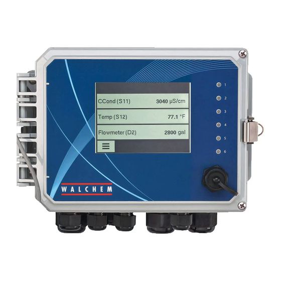
4.0 FUNCTION OVERVIEW Front Panel Figure 18 Front Panel Touchscreen A Home screen is displayed while the controller is on. This display shows a user-defined list of input readings or status of outputs. Touching any of the items on the Home Screen will bring up the item’s Details Screen, where you can access calibration and setting menus. - Page 36 Outputs Menu Configuration Menu HOA Menu Graph Menu Home Page Other icons may appear in the menu screens. Calibration icon appears in sensor input menus and brings up the calibration menu Cancel icon aborts a calibration or setting change The Page Down icon scrolls down to a new page in a list of options. The Page Up icon scrolls up to a new page in a list of options.
-
Page 37: Startup
Overview of the use of icons Changing Numeric Values To change a number, use the Character Delete icon to the digit to be changed. If the new number will be neg- ative, start with touching the minus sign, then use the numeric touchpad and decimal point to type the number (some entries must be integers and the decimal will be ignored and the setting rounded to the nearest integer). - Page 38 If a flow switch or liquid level switch is connected, D1 through D6 (whichever one has the device connected to it) should be set to DI State type (if no switch is connected, select No Sensor). Set the state that will possibly interlock control outputs (refer to the Outputs settings to program which outputs, if any, will be interlocked by the switch).
- Page 39 MAIN MENU/HOME SCREEN OVERVIEW Inputs Nickel (S11) 7.00 g/l pH (S12) 4.50 HOME SCREEN (example) Temp (S13) 77.1 F Generic AI (S21) 30.5% Flowswitch (D1) No Flow SENSOR (S1) Config Nickel (S11) 7.00 g/l Global Settings List of possible Inputs: 4.50.°F Copper Security Settings...
- Page 40 Inputs Main Menu 09:19:01 14-Mar-2017 Config Nickel (S11) 7.00 g/l Inputs ph (S12) 4.50 Outputs Temp (S13) 77.1°F Alarms Graph Generic AI (S21) 30.5% Inputs>Sensor (S11) > Calibration Details Screen SENSOR (S1) Water/Sample Calibration Content varies with One Point Process Calibration sensor type One Point Buffer Calibration Two Point Buffer Calibration...
- Page 41 Outputs OUTPUTS (RELAYS R1-R6) Main Menu 09:19:01 14-Mar-2017 Config On/Off (R1) Inputs Inhibitor (R2) Outputs Additional Settings for Manual Mode: Manual (R1-R16) Flow Timer (R3) Reset Output Timeout Name Alarms Graph HOA Setting Manual (R4) Interlock Channels Mode On Delay Time Minimum Relay Cycle Hand Time Limit Off Delay Time...
- Page 42 OUTPUTS (ANALOG A1-A2) Outputs Main Menu 09:19:01 14-Mar-2017 Manual (R5) Inputs Config Alarm (R6) Outputs Manual (A1) Alarms Graph Retransmit (A2) Outputs>Retransmit (A2) Details Screen Content varies with output type Additional settings for Additional settings for Retransmit (A1-A2) Lag Output (A1-A2) Retransmit Mode: Lag Output Mode: HOA Setting...
- Page 43 CONFIG MENU HOME SCREEN (example) Config Flowswitch (D1) No Flow Main Menu 09:19:01 14-Mar-2017 Global Settings CCond (S11) 3041 µS/cm SENSOR (S1) Inputs Config Security Settings Temp (S12) 77.0°F Network Settings Outputs Network Details Flowswitch (D1) No Flow Alarms Graph Additional Config Settings: Remote Communnications (Modbus) Email Report Settings...
-
Page 44: Shut Down
Outputs (see section 5.3) Program the settings for each output The R1 relay output will be displayed. Touch the relay field to get to the Details screen. Touch the Settings icon. If the name of the relay does not describe the control mode desired, touch the Scroll Down icon until Mode field is displayed. -
Page 45: Alarms Menu
Alarms Menu Touch the Alarms icon to view a list of active alarms. If there are more than six active alarms, the Page Down icon will be shown; touch this icon to bring up the next page of alarms. Touch the Main Menu icon to go back to the previous screen. Inputs Menu Touch the Inputs icon to view a list of all sensor and digital inputs. - Page 46 Calibration Successful or Failed If successful, touch Confirm to put the new calibration in memory. The calibration adjusts the water offset and slope and displays the new slope and the mV in water at both measurement and reference wavelengths. If failed, you may retry the calibration or cancel.
- Page 47 Second Buffer Temperature (only appears if no temperature sensor is detected for sensor types that use automatic temperature compensation) Enter the temperature of the buffer and press Confirm. Second Buffer Value (does not appear if automatic buffer recognition is used ) Enter the value of the buffer being used Rinse Electrode Remove the sensor from the process, rinse it off, and place it in the buffer solution.
- Page 48 Third Buffer Value (does not appear if automatic buffer recognition is used) Enter the value of the buffer being used Rinse Electrode Remove the sensor from the process, rinse it off, and place it in the buffer solution. Touch Confirm when ready.
-
Page 49: Copper/Nickel
Cal Successful or Failed If successful, touch Confirm to save calibration results. The calculated offset and gain will be displayed. If failed, you may retry the calibration or cancel. You may also restore calibration to the factory defaults. The calibration will fail if the offset is more than 2 mA or the gain is not between 0.5 and 2.0. Please restore input signal to process value Put the transmitter back into normal measurement mode if necessary and touch Confirm when ready to resume control. -
Page 50: Contacting Conductivity
5.2.2 Contacting Conductivity Settings Touch the Settings icon to view or change the settings related to the sensor. Alarms Low-Low, Low, High and High-High Alarms limits may be set. Deadband This is the Alarm Deadband. For example, if the High Alarm is 3000, and the dead- band is 10, the alarm will activate at 3001 and deactivate at 2990. -
Page 51: Temperature
Cable Length The controller automatically compensates for errors in the reading caused by varying the length of the cable. Gauge The cable length compensation depends upon the gauge of wire used to extend the cable Cell Constant Do not change unless instructed by the factory. Range Select the range of conductivity that best matches the conditions the sensor will see. -
Page 52: Orp
Buffers Select if calibration buffers will be manually entered, or if they will be automati- cally detected, and if so, which set of buffers will be used. The choices are Manual Entry, JIS/NIST Standard, DIN Technical, or Traceable 4/7/10. Default Temp If the temperature signal is lost at any time, then the controller will use the Default Temp setting for temperature compensation. -
Page 53: Generic Sensor
Smoothing Factor Increase the smoothing factor percentage to dampen the response to changes. For example, with a 10% smoothing factor, the next reading shown will consist of an average of 10% of the previous value and 90% of the current value. Cable Length The controller automatically compensates for errors in the reading caused by vary- ing the length of the cable. -
Page 54: Di State
Cal Required Alarm To get an alarm message as a reminder to calibrate the sensor on a regular schedule, enter the number of days between calibrations. Set it to 0 if no reminders are necessary. Alarm Suppression If any of the relays or digital inputs are selected, any alarms related to this input will be suppressed if the selected relay or digital input is active. -
Page 55: Flow Meter, Paddlewheel Type
Reset Flow Total Enter this menu to reset the accumulated flow total to 0. Touch Confirm to accept, Cancel to leave the total at the previous value and go back. Set Flow Total This menu is used to set the total volume stored in the controller to match the register on the flow meter. - Page 56 While a Total Alarm is active, the linked pump will be controlled based on the Total Alarm Mode setting: Interlock The output will be OFF while the alarm is active. Maintain The alarm condition has no effect on output control. Flow Verify Alarm The W600 monitors the status or current percent output of the channel linked to the feed monitor to determine if a Flow Verify alarm should be activated.
-
Page 57: Virtual Input - Calculation
Reset Flow Total Enter this menu to reset the accumulated flow total to 0. Touch Confirm to accept, Cancel to leave the total at the previous value and go back. Set Flow Total This menu is used to set the total accumulated volume stored in the controller to match a specified volume. -
Page 58: Virtual Input - Raw Value
Input Select the physical input whose value will be used in the calculation shown above as the Input in the formula. Input 2 Select the physical input whose value will be used in the calculation shown above as the Input 2 in the formula. Calculation Mode Select a calculation mode from the list. -
Page 59: Outputs Menu
Outputs Menu Touch the Outputs icon from the Main Menu to view a list of all relay and analog outputs. The Page Down icon pages down the list of outputs, the Page Up icon pages up the list of outputs, the Main Menu icon brings back the previous screen. -
Page 60: Relay, On/Off Control Mode
5.3.2 Relay, On/Off Control Mode Output Details The details for this type of output include the relay on/off state, HOA mode or Interlock status, accumulated on- time, alarms related to this output, current cycle on time, relay type and the current control mode setting. Settings Touch the Settings icon to view or change the settings related to the relay. -
Page 61: Plating Follow
On Delay Time Enter the delay time for relay activation in hours:minutes:seconds. Set the time to 00:00:00 to immediately activate the relay. Off Delay Time Enter the delay time for relay deactivation in hours:minutes:seconds. Set the time to 00:00:00 to immediately deactivate the relay. Total Mode Enter this menu to select the method and program feed totalization Pump Capacity Only appears for As Volume or As Turns. -
Page 62: Relay, Alarm Output Mode
5.3.6 Relay, Alarm Output Mode Output Details The details for this type of output include the relay on/off state, HOA mode or Interlock status, accumulated on- time, alarms related to this output, current cycle on time, relay type and the current control mode setting. Settings Touch the Settings icon to view or change the settings related to the relay. -
Page 63: Relay, Pulse Proportional Control Mode
Off Delay Time Enter the delay time for relay deactivation in hours:minutes:seconds. Set the time to 00:00:00 to immediately deactivate the relay. 5.3.9 Relay, Pulse Proportional Control Mode ONLY AVAILABLE IF CONTROLLER INCLUDES PULSE OUTPUT HARDWARE Output Details The details for this type of output include the relay pulse rate, HOA mode or Interlock status, accumulated on- time, alarms related to this output, current cycle on time, relay type and the current control mode setting. - Page 64 de(t) Output (%) = K e(t) + e(t)dt + T Parameter Description Units e(t) Current Error % of full scale Delta Time Between Readings seconds de(t) Difference Between Current Error & Previous Error % of full scale Parallel The parallel form allows the user to enter all parameters as Gains. In all cases, larger gain values result in faster output response.
- Page 65 and the control elements (pump, valves, etc.) will be sized properly so that the output never reaches its minimum or maximum limit during normal control operations. But with this wind-up suppression feature, overshoot will be minimized should that situation occur. Output Details The details for this type of output include the pulse rate in %, HOA mode or Interlock status, input value, current integral, current and accumulated on-times, alarms related to this output, relay type, and the current control...
-
Page 66: Relay, Dual Set Point Mode
5.3.11 Relay, Dual Set Point Mode Output Details The details for this type of output include the relay on/off state, HOA mode or Interlock status, accumulated on- time, alarms related to this output, current cycle on time, relay type and the current control mode setting. Settings Touch the Settings icon to view or change the settings related to the relay. -
Page 67: Relay, Probe Wash Control Mode
Output Details The details for this type of output include the relay on/off state, HOA mode or Interlock status, accumulated on- time, alarms related to this output, current cycle on time, relay type and the current control mode setting. The cur- rent week number and day of the week is displayed (even if there is no multi-week repetition event programmed). -
Page 68: Relay, Spike Control Mode
The alarm is cleared when the relay is next activated for any reason (the next timer event or HAND mode or “activate with” force on condition). Output Details The details for this type of output include the relay on/off state, HOA mode or Interlock status, accumulated on-time, alarms related to this output, current cycle on time, relay type and the current control mode setting. - Page 69 Interlock Conditions Interlocks override the relay control, but do not change the operation of the timer control. A digital input or output interlock condition does not delay the relay activation. The relay activation duration timer will continue even if the relay is deactivated due to an interlock condition. This will prevent delayed events which can potentially cause problems in they do not occur at the correct time.
-
Page 70: Relay, Or Analog Output, Lag Control Mode
Week Only appears if Repetition is longer than 1 Week. Select the week during which the event will occur. Day Only appears if Repetition is longer than Daily. Select the day of the week during which the event will occur. Start Time Enter the time of day to start the event. - Page 71 The default control operation for the Lead Lag group is that if a condition exists that prevents one relay from being activated, it is skipped and the next output in the group is turned on instead. This situation may occur if the output is experiencing an active Flow Verify alarm or the output is not in Auto mode.
- Page 72 Time Unbalanced This wear leveling mode improves fault-tolerance of the group by varying the wear on each pump by activating each pump for a different percentage of time. In this mode, a primary output is activated most of the time and secondary (auxiliary) output(s) are activated for a smaller percentage of the total output on-time.
- Page 73 Example 1: The Lead output (R1) is set for On/Off control of pH with a setpoint of 8.50, a deadband of 0.20 and a “force lower” control direction. The first Lag output (R2) has a setpoint of 9.00 and a deadband of 0.20. The second Lag output (R3) has a setpoint of 9.50 and a deadband of 0.20.
- Page 74 goes above 8.50, the on-times for each pump are evaluated. If R1 has been on less than 80% of the total time for the two pumps, it is energized. Otherwise, R2 has been on for less than 20% of the total time, so it is energized. If the pH remains above the deadband and does not exceed the second setpoint (8.30 <...
- Page 75 Set point This setting only appears if the control mode of the Lead output is On/Off or Dual Set- point and the Activation Mode above is Setpoint Based. Enter the process value for the input assigned to the Lead output that will trigger an additional output to activate.
-
Page 76: Relay Or Analog Output, Retransmit Mode
Off Mode Output This menu only appears for analog output Lead outputs.Enter the output mA value desired for each output in the group when the output is in Off mode, or being Inter- locked, or during a calibration of the sensor being used as an input. The acceptable range is 0 to 21 mA. -
Page 77: Analog Output, Pid Control Mode
Set point Enter the sensor process value at which the output % will be the programmed minimum %. Proportional Band Enter the sensor process value away from the set point at which the output % will be the programmed maximum %. Minimum Output Enter the lowest output %. - Page 78 Delta Time Between Readings seconds de(t) Difference Between Current Error & Previous Error % of full scale Parallel The parallel form allows the user to enter all parameters as Gains. In all cases, larger gain values result in faster output response. This form is used in the WebMaster controller and is used internally by the Control Module.
- Page 79 Output Details The details for this type of output include the analog output value in %, HOA mode or Interlock status, input value, current integral, current and accumulated on-times, alarms related to this output, and the current control mode setting. Set Point Numeric entry of a process value used as a target for PID control.
-
Page 80: Analog Output, Manual Mode
5.3.19 Analog Output, Manual Mode Output Details The details for this type of output include the analog output %, HOA mode or Interlock status, accumulated on- time, alarms related to this output, current cycle on time, and the current control mode setting. Settings A Manual analog output will activate if the HOA mode is Hand, or if it is Activated With another channel. -
Page 81: Global Settings
5.4.1 Global Settings Date Enter the current year, month and day. Time Enter the current hour (military time), minute, and second. Name Enter the name to help identify the controller when it connects to VTouch. Location Enter the location to help identify the controller when it connects to VTouch. Global Units Select the units to be used for cable length and wire gauge settings, metric or Imperial. -
Page 82: Remote Communications (Modbus)
Alarms Displays any active Network-related alarms DHCP Status Displays if the connection to the LAN using DHCP was successful or not. Controller IP Address Displays the IP address that the controller is currently using. Network Netmask Displays the netmask address that the controller is currently using. Network Gateway Displays the gateway address that the controller is currently using. -
Page 83: Display Settings
Reports Per Day Only appears if Report Type is Datalog/Summary. Only appears if the repetition is set to Hourly. Select the number of reports per day: 2, 3, 4, 6, 8, 12 or 24. The report is sent on the Report Time and then evenly spaced throughout the day. -
Page 84: File Utilities
Auto Dim Time If this is set to a non-zero time, the display backlight will dim if the touchscreen is not touched for that amount of time. Touching the screen will turn the back to normal brightness. Key Beep Select enable to hear a beep when an icon is pressed, or disable for silence 5.4.8 File Utilities File Transfer Status... -
Page 85: Hoa Menu
Display Board Displays the revision number of the display board AO Board Displays the revision number of the analog output board Last Data Log Displays the date and time of the last data log download Battery Power Displays the VDC output of the battery that is used to hold the date and time. The acceptable range is 2.4-3.2 VDC. -
Page 86: 6.0 Operation Using Ethernet
Time Range Select the time range for the X axis of the graph. The time range may also be accessed from the graph view by touching the time range icon in the lower right corner. The resolution of the screen only allows for 84 data points per graph, so not all data points in each time range can be shown. -
Page 87: Navigating The Web
Follow the instructions above to give the controller a fixed IP address that is compatible with the network settings of the computer. Open a browser and type the numeric Controller IP address in the web page address field. The login screen should quickly appear. -
Page 88: Replacing The Fuse Protecting Powered Relays
Warning: Use of non-approved fuses can affect product safety approvals. Specifications are shown below. To insure product safety certifications are maintained, it is recommended that a Walchem fuse be used. Fuse 5 x 20 mm, 6A, 250V Walchem P/N 102834 8.0 TROUBLESHOOTING... -
Page 89: Ph Sensors
Dirty sensor Clean or etch sensor Water/Sample Calibration has not been performed, or per- Perform a Water/Sample Calibration formed incorrectly Condensation inside sensor Allow sensor to dry out. Replace desiccant. Faulty sensor cable or photodetector Repair or replace sensor Faulty sensor receptacle on controller Replace 8.1.2 pH Sensors... -
Page 90: Disinfection Sensors
Possible Cause Corrective Action Dirty electrode Clean electrode Improper wiring of sensor to controller Correct wiring Faulty electrode Replace electrode Faulty preamplifier Replace preamplifier 8.1.6 Disinfection Sensors The calibration will fail if the adjustment to the gain is outside of 0.2 to 10.0, or if the calculated offset is outside of -40 to 40. - Page 91 NO SAMPLE No Sample will be displayed if the measurement signals indicate excess air in the sample. In the Input Details menu, both the Sample Measurement and Sample Reference mV will be between 0.4 and 0.7 times what the readings were in water during the last Water/ Sample Calibration (Water Measurement and Water Reference mV).
- Page 92 The chemical supply has run out. Replenish the chemical supply. The pump or valve or supply line is faulty. Repair or replace the control device. Wrong chemical is being controlled. Replace with correct chemical. The sensor is not responding to changes. Repair or replace sensor.
- Page 93 RANGE ALARM (for sensor inputs) It indicates that the signal from the sensor is out of the normal range. This error condition will stop control of any output using the sensor. This prevents controlling based upon a false sensor reading. If the temperature sensor goes into range alarm, then the controller will go into manual temperature compensation using the Default Temperature setting.
- Page 94 Ethernet card not seated correctly Unplug the network card and plug it back in Faulty Ethernet card Replace Ethernet card WEB SERVER FAILURE This alarm occurs if the web server on the Ethernet circuit board fails Possible Cause Correction Action Web server locked up Try a power cycle to reset it Faulty Ethernet card...
-
Page 95: Procedure For Evaluation Of Conductivity Electrode
SENSOR SOFTWARE VERSION This alarm occurs if a sensor input card with software v2.11 or lower is installed onto a controller board running software v2.13 or higher Possible Cause Correction Action Software is not compatible between boards Perform a Software Upgrade NETWORK SOFTWARE VERSION This alarm occurs if an Ethernet card is installed onto a controller board running a higher software version than the Ethernet card Possible Cause... -
Page 96: Diagnostic Lights
the terminal is not clamped to the plastic jacket, and that the wires are routed to the correct terminal. If there is a junction box installed between the electrode and the controller, check the wiring there as well. You should be able to measure the +5VDC ±5% and -5VDC ±5% vs IN- at the terminal strip. If not, the controller is faulty. -
Page 97: 9.0 Spare Parts Identification
9.0 Spare Parts Identification 191730 Sensor Board 191733 or 191731 Analog Input Board Ethernet Board or 191929 Combination Sensor/Analog Input Board or 192618 Copper/Nickel + pH Input Board 191732 Analog 191738 Output Saftey Cover Board 103864 Screws (6x) 102834 Fuse (W600 & W610 Only) 191578 Power Switch Cable 191734 W600 Power Relay Board... -
Page 98: 10.0 Service Policy
10.0 Service Policy Walchem controllers have a 2-year warranty on electronic components and a 1-year warranty on mechanical parts and electrodes. See Statement of Limited Warranty in front of manual for details. Walchem controllers are supported by a worldwide network of authorized master distributors. Contact your autho- rized Walchem distributor for troubleshooting support, replacement parts, and service.
Need help?
Do you have a question about the W600 Series and is the answer not in the manual?
Questions and answers