Table of Contents
Advertisement
Quick Links
Advertisement
Table of Contents

Related Manuals for Walchem WCU Series


Summary of Contents for Walchem WCU Series
- Page 1 WCU Series Electroless Copper Controller Instruction Manual...
- Page 2 WALCHEM Corporation and for the purposes disclosed in writing at the time of purchase, if any. WALCHEM Corporation's liability under this warranty shall be limited to replacement or repair, F.O.B.
-
Page 3: Table Of Contents
TABLE OF CONTENTS Introduction......................1 Specifications ......................1 Electrical: Input/Output..................1 Mechanical......................2 Unpacking and Installation ..................2 Unpacking the unit ....................2 Mounting the electronic enclosure ................3 Immersible Copper Sensor Installation ..............3 Flow Through Copper Sensor/Sample Loop Installation ........4 Control Module Installation..................8 Icon Definitions .....................9 Electrical Installation .....................9 Function Overview ....................14 Front Panel ......................15... -
Page 4: Introduction
Introduction The WCU310 series copper controllers are optoelectronic on-line analyzers that may be used in variety of applications including electroless copper baths, microetch baths and a number of other chemistries that contain more than 0.10 grams/liter (g/L) of copper ions. There are four relays that may be used as control outputs that are activated simultaneously. -
Page 5: Mechanical
Agency Approvals UL 61010-1, 2 Edition C22,2 No.61010-1 2 Edition CE Safety EN 61010-1 2 Edition CE EMC EN 61326 :1998 Annex A* Note: For EN61000-4-6,3 the controller met performance criteria B. *Class A equipment: Equipment suitable for use in establishments other than domestic, and those directly connected to a low voltage (100-240 VAC) power supply network which supplies buildings used for domestic purposes. -
Page 6: Mounting The Electronic Enclosure
Mounting the electronic enclosure The WCU series controller is supplied with mounting holes on the enclosure. It should be wall mounted with the display at eye level, on a vibration-free surface, utilizing all 4 mounting holes for maximum stability. Use M6 (1/4" diameter) fasteners that are appropriate for the substrate material of the wall. -
Page 7: Flow Through Copper Sensor/Sample Loop Installation
Flow Through Copper Sensor/Sample Loop Installation The copper flow through sensor is designed for out-of-tank monitoring of electroless copper and microetch solutions. The sensor is designed with a glass tube that contains the copper solution that forms a fixed path length between the lamp and receptor module. The solution absorbs light at specific wavelengths in proportion to the copper concentration. - Page 8 WCU with Immersible Sensor CO P PE R CO N TR O L LE R IMMERSIBLE OU T 2 OU T 3 O U T 4 SENSOR P RE V. N EX T 20 FT E X IT EN TE R (80 FT MAX.) POWER PLATING BATH...
- Page 9 The flow through sensor/sample loop must be installed according to the following guidelines: ¾ Mount the sensor on a vibration-free, vertical surface so that the sensor tubing inlet connection is at the bottom and the outlet is at the top. The vertical orientation will prevent air bubbles from being trapped in the sensor.
- Page 10 Application Notes If the distance from the solution to the sensor is further than the recommended length of 25 feet, the maximum lagtime must be calculated from the desired control band to determine a pump flow rate based on a given distance of standard, uniform tubing.
-
Page 11: Control Module Installation
Note: 1 U.S. Gallon = 231 U.S cubic 1 Liter = 61.03 U.S. cubic inches inches Volume of Cooling Coil: 0.018 Gallons Volume of Cooling Plate: 0.023 Gallons 0.068 Liters 0.088 Liters Volume of 3/8" O.D. x 1/4" I.D. (0.59 in3/ft): 0.00255 Gallons/linear ft 0.00965 Liters/linear ft Volume of the system =... -
Page 12: Icon Definitions
WCU310-5xx 240 VAC, 50/60 Hz The various standard wiring options are shown below. Your WCU series controller will arrive from the factory prewired or ready for hardwiring. Depending on your configuration of controller options, you may be required to hardwire some or all of the input/output devices. - Page 13 CAUTION! Proper grounding of this product is required. Any attempt to bypass the grounding will compromise the safety of persons and property. CAUTION! Operating this product in a manner not specified by Walchem may impair the protection provided by the equipment.
- Page 14 Figure 3 Inputs (for power relay board #191236)
- Page 15 4-20mA (Optional 4-20 mA Board) (Grounding Stud) NEUTRAL 190873 BLK (115V) GRN (115V) BRN (230V) GRN/YEL (230V) WHT (115V) BLU (230V) (INPUTS - ALL MODELS) FLOW SWITCH Green White White w/Green Stripe w/Blue (Polarity Stripe To Grounding critical) Blue Stud Orange Panel Mount Power Supply...
- Page 16 Note: All relay outputs are internally powered switching line voltage. Note: The Alarm Relay is non-programmable. Refer to the Main Menu diagram on page 16 for the list of error conditions that trigger the alarm relay. Figure 4 Outputs (for power relay board #191236)
- Page 17 Chart Recorder 4-20mA (Optional 4-20 mA Board) (Grounding Stud) NEUTRAL 190873 OUTPUTS ALRM OUT4 OUT3 OUT2 OUT1 N.O. N.O. N.O. N.O. N.C. N .O. Alarm Pump(s) Figure 4a Outputs (for power relay board #190873)
-
Page 18: Function Overview
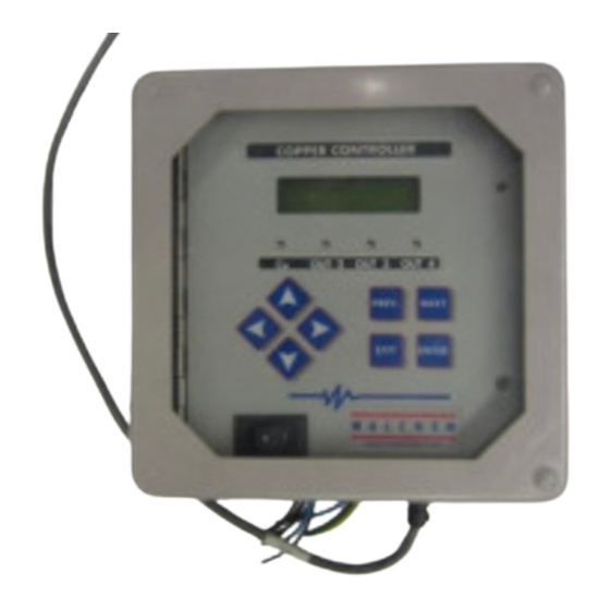
Function Overview Front Panel Backlit LCD Display C O P PER C O N T R O LL ER Output LEDs Setting Adjustment Keys O U T 2 O U T 3 O U T 4 P RE V. N E X T E X IT E N TE R Menu/Function Keys... -
Page 19: Keypad
ALL of the changes for that menu screen. Access Code The WCU series controller is shipped with the access code disabled. If you wish to enable it, see Section 5.8 for operation. With the access code enabled, any user can view parameter settings, but not change them. -
Page 20: Shutdown
To return to the summary screen, press the EXIT key until you return to this screen. The controller will automatically return to this screen after 10 minutes. Normal Startup Startup is a simple process once your set points are in memory. Simply check your supply of chemicals, turn on the controller, calibrate the sensor if necessary and it will start controlling. -
Page 21: Sensor Menu
Sensor Menu The sensor menu provides the following settings: Calibration history (informational only), 1 point calibration, Days between Calibration, Units of measure, Control mode, and New sensor set-up. Each is discussed in detail below. Refer to the Sensor Menu Chart. Note: If you are programming the unit for the first time, scroll to the Cu Mode menu and set the "Cu Mode"... - Page 22 Main Menu...
- Page 23 Self Test This feature is a diagnostic tool which can help isolate a problem between the sensor and controller. Before initiating the self test, the sensor MUST be disconnected from the controller in order to function properly. When ENTER is pressed the controller disables the sensor inputs and injects 2 test signals, simulating a properly functioning sensor.
- Page 24 Sensor Menu...
-
Page 25: Output 1 Menu
Output 1 Menu The Out 1 menu is used to set the control set point, and to configure the timer/totalizer to keep track of replenishment in the desired way. This menu provides the following settings: Total 1, Set Point, Dead Band, Time Limit, Interlock, and H O A. - Page 26 Output 1 Menu...
- Page 27 Dead Band Use the arrow keys to set the desired dead band, then press ENTER. If the set point is 2.50 g/L, and the dead band is 0.05 g/L, then the relay will close at 2.50 g/L and open 0.05 g/L away from 2.50 g/L (2.55 g/L if set for EC, 2.45 g/L if set for microetch).
- Page 28 Output 2,3,4 Menu...
-
Page 29: Output 2, 3, And 4 Menus
Output 2, 3, and 4 Menus The Out 2, 3 and 4 menus are separate from each other but operate in exactly the same way. Each menu provides the Total and H O A settings. These additional outputs are activated simultaneously with output 1 and are provided to be able to add other bath components in proportion to the copper, and display independent replenishment totals. -
Page 30: Clock Menu
Clock Menu The clock menu is used to set the date and time that the controller uses to schedule calibration prompts. There is only one menu selection: Set Clock. Set Clock Press ENTER to set the clock. Use the arrow keys to change the year, date, and month, then press ENTER. -
Page 31: Alarm Menu
Alarm Menu This menu is used to set the high and low copper concentration alarm points. Press ENTER to adjust the alarm set points. % Low Alarm Use the arrow keys to change the % below the set point copper concentration that will trigger a low alarm. -
Page 32: Access Code Menu
Calibrate This menu, in conjunction with an ammeter, is used to calibrate the mA output. Press ENTER to start the calibration. Fixed 4 mA Out The controller will output 4.00 mA. Adjust the chart recorder or data logger per its instruction so that the process value displayed is what is expected for a 4.00 mA input. - Page 33 Possible status screens are: Access Code REQ, Access Code OK, and Access Code DIS. The first indicates that the access code is required to alter settings. The second indicates that the access code is required and has been entered correctly, and the last indicates that the access code has been disabled.
-
Page 34: Maintenance
Warning: Use of non-approved fuses can affect product safety approvals. Fuse ratings depend on controller power rating. Specifications are shown below. To insure product safety certifications are maintained, it is recommended that a Walchem fuse is used. Controller Rating Walchem PN... -
Page 35: Troubleshooting
Troubleshooting CAUTION: Disconnect power to the controller before opening front panel! Troubleshooting and repair of a malfunctioning controller should only be attempted by qualified personnel using caution to ensure safety and limit unnecessary further damage. Contact the factory. Error Messages HIGH ALARM The summary screen will display an H at the right side of the bar graph if the copper concentration rises above the high alarm set point. - Page 36 Possible Cause Corrective Action 1. Liquid level too low for Increase liquid level immersible sensor. 2. Sample pump failure. Repair sample pump 3. Leak in or blockage of sample line. Repair sample line 4. Partial plate out of sensor. Etch sensor. 5.
- Page 37 Possible Cause Corrective Action 1. Condensation inside sensor Allow to dry out thoroughly 2. Faulty new sensor set-up Repeat new sensor set-up with clean water 3. Sensor disconnected Reconnect sensor CALIBRATION TIME The controller will display this prompt based upon the setting of the "Days between cal"...
-
Page 38: Service Policy
Consult your factory representative for service options. Service Policy The WCU Series Copper Controller has a 2-year warranty on electronic components and a 1-year warranty on mechanical parts (keypad, terminal strip and relays). We stock circuit boards for immediate exchange after we have isolated the cause of the problem.
Need help?
Do you have a question about the WCU Series and is the answer not in the manual?
Questions and answers