Table of Contents

Related Manuals for Walchem WDB400 Series


Summary of Contents for Walchem WDB400 Series
- Page 1 W A L C H E M WDB400 Controllers WDB400 Series Dual Boiler Controller Instruction Manual Walchem Corporation Five Boynton Road Hopping Brook Park Holliston, MA 01746 USA TEL: 508-429-1110 FAX: 508-429-7433 WEB: www.walchem.com...
- Page 2 WALCHEM Corporation and for the purposes disclosed in writing at the time of purchase, if any. WALCHEM Corporation's liability under this warranty shall be limited to replacement or repair, F.O.B. Holliston, MA U.S.A. of any defective equipment or part which, having been returned to WALCHEM Corporation, transportation charges prepaid, has been inspected and determined by WALCHEM Corporation to be defective.
-
Page 3: Table Of Contents
Table of Contents INTRODUCTION........................1 SPECIFICATIONS .........................2 Measurement Performance ....................2 Electrical: Input/Output .......................2 Mechanical .........................2 WDB Variables and their Limits..................3 UNPACKING & INSTALLATION....................4 Unpacking the unit......................4 Mounting the electronic enclosure..................4 Installation ..........................4 Icon Definitions ........................8 Electrical installation ......................8 FUNCTION OVERVIEW ......................12 Front Panel ........................12 Display..........................12 Keypad ..........................13... -
Page 4: Introduction
INTRODUCTION The Walchem WDB400 Series controllers offer conductivity control of boiler water and control of chemical feed of two separate boilers. The chemical feed pump may be selected to operate in one of the following modes: Feed and Blowdown Feed and Blowdown with Lockout... -
Page 5: Specifications
SPECIFICATIONS Measurement Performance Conductivity Range 0 - 10,000 µS/cm (microSiemens/centimeter) Conductivity Resolution 1 µS/cm Conductivity Accuracy 10 - 10,000 µS/cm ±1% of reading 0 - 10 µS/cm ±20% of reading Temperature Range 32 - 392°F (0 - 200°C) Temperature Resolution 0.1°C Temperature Accuracy ±... -
Page 6: Wdb Variables And Their Limits
WDB Variables and their Limits Low Limit High Limit Conductivity menu PPM Conversion Factor 0.200 ppm/µS/cm 1.000 ppm/µS/cm Interval Time (sampling) 5 minutes 24:00 hours Duration Time (sampling) 1 minute 59 min: 59 sec Hold Time 1 second 499 min: 59 sec Blowdown Time 1 minute 8 hrs: 20 min... -
Page 7: Unpacking & Installation
UNPACKING & INSTALLATION Unpacking the unit Inspect the contents of the carton. Please notify the carrier immediately if there are any signs of damage to the controller or its parts. Contact your distributor if any of the parts are missing. The carton should contain: a WDB series controller and instruction manual. - Page 8 5. Mount the electrode in the side branch of a cross in a horizontal run of pipe. This will minimize entrapment of steam around the electrode and will allow any solids to pass through. 6. There MUST be a flow restriction after the electrode and/or control valve in order to provide back pressure.
- Page 9 5. Determine the Orifice or Flow Control Valve Size for this Blowdown Rate Use the following graphs to select a flow control device: Flow Rate in Lbs/hr for Various Orifices 18000 16000 14000 12000 1/8 inch dia 10000 3/16 inch dia 1/4 inch dia 8000 5/16 inch dia...
- Page 10 Manual Blowdown (Normally Closed) To Drain DRAIN Boiler Controller Install accessories PREV NEXT either vertically or EXIT ENTER horizontally, per manufacturer's www.walchem.com instructions. Flow Motorized Skimmer Blowdown Line Control Ball 3/4" Min. up to Electrode Valve or Orifice Solenoid Valve Union...
-
Page 11: Icon Definitions
National, State and Local codes! Proper grounding of this product is required. Any attempt to bypass the grounding will compromise the safety of persons and property. Operating this product in a manner not specified by Walchem may impair the protection provided by the equipment. - Page 12 AUX B BLOWDOWN A CONDUCTIVITY WATER METER B SPARES ELECTRODE A (OPTIONAL) CONDUCTIVITY ELECTRODE B 4-20mA 1 (OPTIONAL) 4-20mA 2 (OPTIONAL) SPARE FLOW SWITCH A BLOWDOWN B WATER METER A POWER (OPTIONAL) FLOW SWITCH B (OPTIONAL) (OPTIONAL) AUX A ALARM Figure 3 Conduit/Wiring Configuration...
- Page 13 BLEED FEED N.C. N.O. N.C. N.O. L1 L2/N GROUND STUD SYSTEM B COND L1 L2/N SHIELD WHT 120V BLU 240V SHIELD SYSTEM A Do not connect shield drain wire SYSTEM A SYSTEM B at this end! COND G WR B FLOW SW 1 FLOW SW 2 FLOW MTR 1...
- Page 14 Chart Chart Recorder Recorder BLEED FEED BOI 1 BIO 2 ALARM N.C. N.O. N.C. N.O. N.C. N.O. N.C. N.O. N.C. N.O. N.C. N.O. L2/N GROUND STUD GRN 120V GRN 120V GRN/YEL 240V GRN/YEL 240V BLOWDN B BLOWDN A AUX A AUX B ALARM L2/N...
-
Page 15: Function Overview
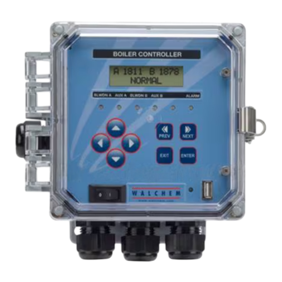
FUNCTION OVERVIEW Front Panel Backlit LCD Display Output LEDs Setting Adjustment Keys Menu/Function Keys USB LED On/Off Power Switch USB Connector Figure 6 Front Panel Display A summary screen is displayed while the WDB controller is on. The operating conditions that are displayed on the bottom line of this display are Hi Alarm A, Hi Alarm B, Low Alarm A, Low Alarm B, Temp Err A, Temp Err B, Cond Err A, Cond Err B, No Flow A, No Flow B, Blodown Timeout A, Blodown Timeout B, Blowdown A, Blowdown B, Feed A Timeout, Feed B Timeout, Feed A, Feed B,... -
Page 16: Keypad
Keypad The keypad consists of 4 directional arrow keys and 4 function keys. The arrows are used to move the adjustment cursor and change settings, while the function keys are used to enter values, and navigate the various menu screens. The function keys are , and (previous). -
Page 17: Operation
OPERATION These units control continuously while power is applied. Programming is accomplished via the local keypad and display. To view the top level menu, press any key. The menu structure is grouped by inputs and outputs. Each input has its own menu for calibration and unit selection as needed. Each output has its own setup menu including set points, timer values and operating modes as needed. - Page 18 Figure 8 Main Menu...
-
Page 19: Conductivity (A Or B) Menu
Conductivity (A or B) Menu The conductivity menu provides the following settings: Calibration, Self Test, Unit selection, and Sampling mode setup. Additional settings are also discussed below. Refer to figure 9, Conductivity Menu Chart. Calibrate To Calibrate the conductivity, use either a hand held meter, or a standard solution, and adjust the controller to match. - Page 20 BlowTime This is the length of time of the blowdown used in Intermittent Sampling with Timed Blowdown sampling mode. This is set in Hours:Minutes and can be set from 1 minute to 8 hours 20 minutes. At the end of the blowdown time, the controller will check the conductivity of a held sample once again. If the conductivity is still above the set point, another blowdown cycle will occur.
-
Page 21: Temperature (A Or B) Menu
Temperature (A or B) Menu The Temperature menu provides the following settings: Calibration, Unit selection. The Temperature menu will be indicated on the display by one of the following: Temperature Normal operation Temp 270°F Normal operation Temp Error Indicates that there is a problem with the temperature input. See figure 10. Calibrate This menu only appears if a temperature element is connected at power-up. -
Page 22: Blowdown (A Or B) Menu
Blowdown (A or B) Menu The Blowdown Menu provides the following settings: Set Point, Dead Band, Time Limit, Control Direction, HOA. The Blowdown menu will be indicated on the display by one of the following: (The 'A' indicates that the output is being controlled automatically.) Blowdn A Indicates that the blowdown output is currently OFF. - Page 23 Figure 11 Blowdown (A or B) Menu...
-
Page 24: Auxiliary Menu
Auxiliary Menu The Auxiliary output may be used either to control a chemical feed pump or as an alarm. When setting up the controller for the first time, the Output Mode should be selected first. Press ENTER at the Aux menu, scroll to the Output Mode menu and press again . - Page 25 Feed Based on Time/Cont. (Time per contact.) This determines the length of time that the feed pump should be on for each contact Water Contactor that is received. Mode ÷ Contacts By This setting allows a divider to be entered. The divider will count actual contacts from the meter until the setting is reached before a contact is considered to be received.
- Page 26 Figure 12 Auxiliary Menu...
-
Page 27: Time Menu
Time Menu This menu has only one choice, to set the Time used for Datalogs. This menu will appear as follows: Time: Mon 10:20 Set Time Press ENTER to set the Time. Use the arrow keys to adjust the day and time and then press ENTER to store or EXIT to discard. -
Page 28: 4-20Ma (A Or B) Menu
4-20mA (A or B) Menu This menu is only available if the 4-20mA output board is installed in the controller. Installing this option board on the lower power supply board in the controller will assign it to Boiler A. Installing a 4-20mA option board on the top front panel assembly assigns the output to Boiler B. -
Page 29: Access Code Menu
Access Code Menu This menu determines whether the access code feature of the controller is enabled or disabled and allows you to customize the access code to your own value. The access code controls whether or not you are allowed to change the parameters in the controller. With the access code disabled, any user may change any parameter. -
Page 30: Datalog Menu
Datalog Menu This is indicated in the model code by the letter U at the end of the model code. This menu allows you to save data from the controller to a USB flash drive. The controller has four logs, the Current Datalog, the Backup Datalog, the Event Log, and the Reset Log. - Page 31 Datalog Menu 2000 µS 67° F Datalog ENTER EXIT Next Next Next Datalog Datalog Datalog Datalog Backup DataLog Copy Event Log Copy Reset Log Current Datalog Prev Prev Prev Possible Status Screens ENTER EXIT ENTER EXIT ENTER EXIT ENTER EXIT Transfer Success Datalog Datalog...
-
Page 32: Config Menu
5.10 Config Menu This menu allows you to export a file that contains all of the set points in the controller to a USB flash disk drive, and then later import the set points into another controller. Export Config Place a USB flash drive with at least 10 MB capacity into the USB port on the front panel of the controller. -
Page 33: Upgrade Menu
5.11 Upgrade Menu This menu is used to upgrade the software to a newer version. If a new version of the software is available, an upgrade file will be posted on our web site. Save this file to a USB flash disk drive. It needs to be the only executable (.exe file extension) file stored on the root directory of the stick. -
Page 34: Maintenance
Warning: Use of non-approved fuses can affect product safety approvals. Fuse ratings depend on controller power rating. Specifications are shown below. To insure product safety certifications are maintained, it is recommended that a Walchem fuse is used. F1 Fuse Walchem P/N... -
Page 35: Troubleshooting
TROUBLESHOOTING CAUTION: Disconnect power to the controller before opening front panel! Troubleshooting and repair of a malfunctioning controller should only be attempted by qualified personnel using caution to ensure safety and limit unnecessary further damage. Contact the factory. Error Messages HIGH ALARM - (main summary screen only) The summary screen will display an H at the right end of the bar graph if the conductivity rises above the high conductivity alarm set point. - Page 36 BLODOWN TIMEOUT This error condition will stop conductivity control. It is caused by the blowdown output being activated for longer than the programmed Blowdown Time Limit. Possible Cause Corrective Action Programmed value too low for normal conditions. Increase Blowdown Time Limit. Blowdown flow rate too low.
-
Page 37: Conductivity Readout Does Not Change
Conductivity Readout Does Not Change If the readout is stuck at or near zero: Possible Cause Corrective Action 1. Dry electrode Check for flow through system. 2. Electrode is disconnected. Check wiring to electrode. Go to self-test menu, as described in section 5.2 If readout changes to 900- 1100, the problem is with electrode or connections. -
Page 38: No Display
Factory authorized repairs that are received by next-day-air will be returned within 24 hours. Normal priority for returns is two weeks. Out of warranty repairs or circuit board exchanges are done on a flat fee basis after the warranty is expired. WALCHEM CORPORATION 5 BOYNTON ROAD HOPPING BROOK PARK HOLLISTON, MA 01746 USA... - Page 39 TEL: 508-429-1110 FAX: 508-429-7433 WWW.WALCHEM.COM...
Need help?
Do you have a question about the WDB400 Series and is the answer not in the manual?
Questions and answers