
Subscribe to Our Youtube Channel
Related Manuals for VIPA System 300S


Summary of Contents for VIPA System 300S
- Page 1 VIPA System 300S CPU | 314-6CF03 | Manual HB140 | CPU | 314-6CF03 | GB | 16-43 SPEED7 CPU 314ST...
- Page 2 VIPA GmbH Ohmstr. 4 91074 Herzogenaurach Telephone: +49 9132 744-0 Fax: +49 9132 744-1864 Email: info@vipa.com Internet: www.vipa.com 314-6CF03_000_CPU 314ST,3,GB - © 2016...
-
Page 3: Table Of Contents
VIPA System 300S Table of contents Table of contents General..................6 1.1 Copyright © VIPA GmbH ........... 6 1.2 About this manual.............. 7 1.3 Safety information.............. 8 Basics..................10 2.1 Safety information for users..........10 2.2 Operating structure of a CPU........... 11 2.2.1 General................ - Page 4 5.8.1 Parameterization via Siemens CPU......64 5.8.2 Parameters CPU............65 5.8.3 Parameters for DP............67 5.8.4 Parameters for MPI/DP ..........68 5.9 Setting VIPA specific CPU parameters......69 5.9.1 Proceeding..............69 5.9.2 VIPA specific parameters..........71 5.10 Project transfer............... 74 5.10.1 Transfer via MPI/PROFIBUS........
- Page 5 10.3 TIA Portal - Hardware configuration - I/O modules..218 10.4 TIA Portal - Hardware configuration - Ethernet PG/OP channel................. 219 10.5 TIA Portal - Setting VIPA specific CPU parameters..222 10.6 TIA Portal - VIPA-Include library........225 10.7 TIA Portal - Project transfer.......... 226...
-
Page 6: General
General 1.1 Copyright © VIPA GmbH All Rights Reserved This document contains proprietary information of VIPA and is not to be disclosed or used except in accordance with applicable agree- ments. This material is protected by the copyright laws. It may not be repro-... -
Page 7: About This Manual
Tel.: +49 9132 744-1150 (Hotline) EMail: support@vipa.de 1.2 About this manual Objective and contents This manual describes the SPEED7 CPU 314-6CF03 of the CPU from VIPA. It contains a description of the construction, project imple- mentation and usage. Product Order no. as of state:... -
Page 8: Safety Information
General VIPA System 300S Safety information Structure of the manual The manual consists of chapters. Every chapter provides a self-con- tained description of a specific topic. Guide to the document The following guides are available in the manual: An overall table of contents at the beginning of the manual... - Page 9 VIPA System 300S General Safety information Documentation The manual must be available to all personnel in the project design department installation department commissioning operation CAUTION! The following conditions must be met before using or commissioning the components described in this manual: –...
-
Page 10: Basics
Safety information for users Basics 2.1 Safety information for users Handling of electro- VIPA modules make use of highly integrated components in MOS- static sensitive modules Technology. These components are extremely sensitive to over-vol- tages that can occur during electrostatic discharges. The following symbol is attached to modules that can be destroyed by electrostatic discharges. -
Page 11: Operating Structure Of A Cpu
The CPU contains a standard processor with internal program memory. In combination with the integrated SPEED7 technology the unit provides a powerful solution for process automation applications within the System 300S family. A CPU supports the following modes of operation: cyclic operation... -
Page 12: Operands
Basics VIPA System 300S Operating structure of a CPU > Operands 2.2.3 Operands The following series of operands is available for programming the CPU: Process image and periphery Bit memory Timers and counters Data blocks Process image and The user application can quickly access the process image of the periphery inputs and outputs PIO/PII. -
Page 13: Cpu 314-6Cf03
– Digital input: 8xDC 24V with interrupt capability, 4 counter – Digital input/output: 8xDC 24V, 0.5A Modules and CPUs of the System 300S from VIPA and Siemens may be used at the bus as a mixed configuration. The user application is stored in the battery buffered RAM or on an additionally pluggable MMC storage module. - Page 14 2Mbyte by means of a MCC memory extension card. SPEED-Bus The SPEED-Bus is a 32bit parallel bus developed from VIPA. Via the SPEED-Bus you may connect up to 10 SPEED-Bus modules to your CPU. HB140 | CPU | 314-6CF03 | GB | 16-43...
- Page 15 SPEED-Bus are plugged-in at the left side of the CPU via a special SPEED-Bus rail. VIPA delivers profile rails with integrated SPEED-Bus for 2, 6, or 10 SPEED-Bus peripheral modules with different lengths. Each SPEED-Bus rail has a slot for an external power supply.
-
Page 16: General Data
Basics VIPA System 300S General data 2.4 General data Conformity and approval Conformity 2014/35/EU Low-voltage directive 2014/30/EU EMC directive Approval Refer to Technical data others RoHS 2011/65/EU Product is lead-free; Restriction of the use of certain hazardous substances in electrical and... - Page 17 VIPA System 300S Basics General data Mounting conditions Mounting place In the control cabinet Mounting position Horizontal and vertical Standard Comment Emitted interfer- EN 61000-6-4 Class A (Industrial area) ence Noise immunity EN 61000-6-2 Industrial area zone B EN 61000-4-2...
-
Page 18: Assembly And Installation Guidelines
CPU, the SPEED-Bus peripheral modules are connected via a SPEED-Bus bus connector at the left side of the CPU. VIPA delivers profile rails with integrated SPEED-Bus for 2, 6 or 10 SPEED-Bus peripheral modules with different lengths. Serial Standard bus The single modules are directly installed on a profile rail and con- nected via the backplane bus coupler. - Page 19 VIPA System 300S Assembly and installation guidelines Installation dimensions Dimensions Installation dimensions HB140 | CPU | 314-6CF03 | GB | 16-43...
-
Page 20: Assembly Speed-Bus
Assembly and installation guidelines VIPA System 300S Assembly SPEED-Bus 3.3 Assembly SPEED-Bus Pre-manufactured For the deployment of SPEED-Bus modules, a pre-manufactured SPEED-Bus profile rail SPEED-Bus rail is required. This is available mounted on a profile rail with 2, 6 or 10 extension slots. - Page 21 VIPA System 300S Assembly and installation guidelines Assembly SPEED-Bus Installation of the pro- Bolt the profile rail with the background (screw size: M6), so that file rail you still have minimum 65mm space above and 40mm below the profile rail. Please look for a low-impedance connection between profile rail and background.
- Page 22 Assembly and installation guidelines VIPA System 300S Assembly SPEED-Bus To connect the SPEED-Bus modules, plug it between the trian- gular positioning helps to a slot marked with "SLOT ..." and pull it down. Fix the CPU by screwing. Installation CPU without...
-
Page 23: Assembly Standard Bus
VIPA System 300S Assembly and installation guidelines Assembly standard bus CAUTION! – The power supplies must be released before instal- lation and repair tasks, i.e. before handling with the power supply or with the cabling you must discon- nect current/voltage (pull plug, at fixed connection switch off the concerning fuse)! –... - Page 24 VIPA System 300S Assembly standard bus Bus connector For the communication between the modules the System 300S uses a backplane bus connector. Backplane bus connectors are included in the delivering of the peripheral modules and are clipped at the module from the backside before installing it to the profile rail.
-
Page 25: Cabling
VIPA System 300S Assembly and installation guidelines Cabling Click the CPU downwards and bolt it like shown. 10. Repeat this procedure with the peripheral modules, by clicking a backplane bus connector, stick the module right from the modules you've already fixed, click it downwards and connect it with the backplane bus connector of the last module and bolt it. - Page 26 Assembly and installation guidelines VIPA System 300S Cabling CageClamp technology For the cabling of power supply of a CPU, a green plug with Cage- (green) Clamp technology is deployed. The connection clamp is realized as plug that may be clipped off carefully if it is still cabled.
-
Page 27: Installation Guidelines
VIPA System 300S Assembly and installation guidelines Installation guidelines Front connector I/O 40 pole front connector order number 392-1AM00 periphery Open the front flap of your I/O module. Bring the front connector in cabling position. For this you plug the front connector on the module until it locks. - Page 28 The components of VIPA are developed for the deployment in indus- trial environments and meets high demands on the EMC. Neverthe- less you should project an EMC planning before installing the compo- nents and take conceivable interference causes into account.
- Page 29 VIPA System 300S Assembly and installation guidelines Installation guidelines Proof the correct fixing of the lead isolation. – Data lines must be laid isolated. – Analog lines must be laid isolated. When transmitting signals with small amplitudes the one sided laying of the isolation may be favourable.
- Page 30 Assembly and installation guidelines VIPA System 300S Installation guidelines To fix the isolation tangles use cable clamps out of metal. The clamps must clasp the isolation extensively and have well contact. Lay the isolation on an isolation rail directly after the entry of the cable in the cabinet.
-
Page 31: Hardware Description
VIPA System 300S Hardware description Properties Hardware description 4.1 Properties CPU 314-6CF03 SPEED7 technology and SPEED-Bus integrated 512kbyte work memory integrated (256kbyte code, 256kbyte data) Work memory expandable to max. 2Mbyte (1Mbyte code, 1Mbyte data) 2Mbyte load memory PROFIBUS DP master integrated (DP-V0, DP-V1) -
Page 32: Structure
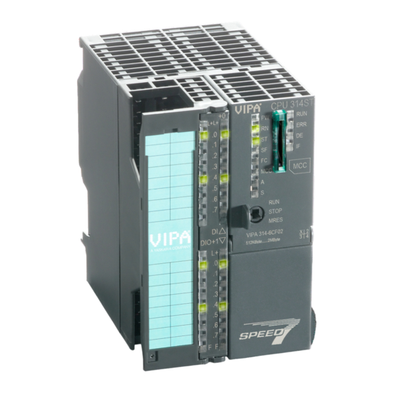
Hardware description VIPA System 300S Structure > Interfaces 4.2 Structure 4.2.1 General CPU 314-6CF03 1 LEDs of the integrated PROFIBUS DP master 2 Storage media slot (lockable) 3 LEDs of the CPU part 4 LEDs of the I/O part 5 Operating mode switch CPU... - Page 33 VIPA System 300S Hardware description Structure > Interfaces The power supply is protected against polarity inversion and over- current. The internal electronic is galvanically connected with the supply voltage. Each SPEED-Bus rail has a slot for an external power supply. This allows you to raise the maximum current at the back plane bus.
-
Page 34: Memory Management
As external storage medium for applications and firmware you may use a MMC storage module (Multimedia card). The VIPA storage media are pre-formatted with the PC format FAT16 and can be accessed via a card reader. After PowerON respectively an overall reset the CPU checks, if there is a storage medium with data valid for the CPU. -
Page 35: Battery Backup For Clock And Ram
VIPA System 300S Hardware description Structure > Battery backup for clock and RAM CAUTION! If the media was already unlocked by the spring mech- anism, with shifting the sliding mechanism, a just installed memory card can jump out of the slot! 4.2.5 Battery backup for clock and RAM... -
Page 36: Operating Mode Switch
Hardware description VIPA System 300S Structure > LEDs 4.2.6 Operating mode switch With the operating mode switch you may switch the CPU between STOP and RUN. During the transition from STOP to RUN the operating mode START-UP is driven by the CPU. - Page 37 VIPA System 300S Hardware description Structure > LEDs Meaning (RUN) (STOP) (SFAIL) (FRCE) (MMC) Firmware update ○ ● ● The alternate blinking indicates that there is new firmware on the memory card. ○ ○ ● The alternate blinking indicates that a firmware update is executed.
- Page 38 Hardware description VIPA System 300S Structure > LEDs Slave operation Meaning (RUN) (ERR) green green ○ ○ ○ ○ Slave has no project respectively PtP is active. ○ ○ ○ Slave is without master. ○ ○ * Alternate flashing at configuration faults.
-
Page 39: In-/Output Range Cpu 314-6Cf03
VIPA System 300S Hardware description Structure > In-/Output range CPU 314-6CF03 4.2.8 In-/Output range CPU 314-6CF03 Overview CPU The CPU 314-6CF03 has the following analog and digital in- and 314-6CF03 output ranges integrated in one casing: Analog input: 4x12Bit, 1xPt100... - Page 40 Hardware description VIPA System 300S Structure > In-/Output range CPU 314-6CF03 CPU 314-6CF03: Analog part pin assignment and status indi- cator Assignment LEDs Description Power supply DC 24V AIO LED (green) Voltage measurement channel 0 Supply voltage Current measurement channel 0...
-
Page 41: Technical Data
VIPA System 300S Hardware description Technical data CPU 314-6CF03: Digital part pin assignment and status indicator Assignment LEDs Description Power supply +DC 24 V DI .0 ..7 I+0.0 / Counter 0(A) LED (green) I+0.1 / Counter 0(B) I+0.0 ... I+0.7 I+0.2 / Gate0/Latch0/Reset0... - Page 42 Hardware description VIPA System 300S Technical data Order no. 314-6CF03 Power loss 14 W Technical data digital inputs Number of inputs Cable length, shielded 1000 m Cable length, unshielded 600 m Rated load voltage DC 24 V Reverse polarity protection of rated load ü...
- Page 43 VIPA System 300S Hardware description Technical data Order no. 314-6CF03 Total current per group, horizontal configura- tion, 40°C Total current per group, horizontal configura- tion, 60°C Total current per group, vertical configuration Output voltage signal "1" at min. current L+ (-0.8 V) Output voltage signal "1"...
- Page 44 Hardware description VIPA System 300S Technical data Order no. 314-6CF03 Current consumption from load voltage L+ 85 mA (without load) Voltage inputs ü Min. input resistance (voltage range) 120 kΩ Input voltage ranges -10 V ... +10 V 0 V ... +10 V Operational limit of voltage ranges +/-0.3%...
- Page 45 VIPA System 300S Hardware description Technical data Order no. 314-6CF03 Operational limit of resistance thermometer +/-0.6% ranges Operational limit of resistance thermometer ranges with SFU Basic error limit thermoresistor ranges +/-0.4% Basic error limit thermoresistor ranges with Destruction limit resistance thermometer inputs max.
- Page 46 Hardware description VIPA System 300S Technical data Order no. 314-6CF03 Max. capacitive load (current range) 1 µF Max. inductive load (current range) 30 mA Output voltage ranges -10 V ... +10 V 0 V ... +10 V Operational limit of voltage ranges +/-0.4%...
- Page 47 VIPA System 300S Hardware description Technical data Order no. 314-6CF03 Mode period measurement Gate input available ü Latch input available ü Reset input available ü Counter output available ü Load and working memory Load memory, integrated 2 MB Load memory, maximum...
- Page 48 Hardware description VIPA System 300S Technical data Order no. 314-6CF03 Between channels and power supply Max. potential difference between circuits DC 75 V/ AC 50 V Max. potential difference between inputs (Ucm) - Max. potential difference between Mana and Mintern (Uiso) Max.
- Page 49 VIPA System 300S Hardware description Technical data Order no. 314-6CF03 Maximum nesting depth per priority class Maximum nesting depth additional within an error OB Time Real-time clock buffered ü Clock buffered period (min.) Accuracy (max. deviation per day) 10 s...
- Page 50 Hardware description VIPA System 300S Technical data Order no. 314-6CF03 S7 basic communication, user data per job 76 Byte S7 communication ü S7 communication as server ü S7 communication as client S7 communication, user data per job 160 Byte Number of connections, max.
- Page 51 VIPA System 300S Hardware description Technical data Order no. 314-6CF03 5V DC Power supply max. 90mA, isolated 24V DC Power supply max. 100mA, non-isolated Functionality MPI Number of connections, max. PG/OP channel ü Routing ü Global data communication ü S7 basic communication ü...
- Page 52 Hardware description VIPA System 300S Technical data Order no. 314-6CF03 S7 communication ü S7 communication as server ü S7 communication as client Direct data exchange (slave-to-slave communi- cation) DPV1 ü Transmission speed, min. 9.6 kbit/s Transmission speed, max. 12 Mbit/s Automatic detection of transmission speed Transfer memory inputs, max.
- Page 53 VIPA System 300S Hardware description Technical data Order no. 314-6CF03 Type of interface Ethernet 10/100 MBit Connector RJ45 Electrically isolated ü PG/OP channel ü Number of connections, max. Productive connections Housing Material Mounting Rail System 300 Mechanical data Dimensions (WxHxD)
-
Page 54: Deployment Cpu 314-6Cf03
Deployment CPU 314-6CF03 VIPA System 300S Start-up behavior Deployment CPU 314-6CF03 5.1 Assembly Ä Chapter 3 Information about assembly and cabling: ‘Assembly and installation guidelines’ on page 18 5.2 Start-up behavior Turn on power supply After the power supply has been switched on, the CPU changes to the operating mode the operating mode lever shows. -
Page 55: Addressing
Now you may extend your system with up to 3 profile rails by starting each with an IM 361 from Siemens at slot 3. Considering the max total current with the CPU 314-6CF03 from VIPA up to 32 modules may be arranged in a row. Here the installation of the line connections IM 360/361 from Siemens is not required. - Page 56 Deployment CPU 314-6CF03 VIPA System 300S Addressing > Addressing Define addresses by You may access the modules with read res. write accesses to the hardware configuration peripheral bytes or the process image. To define addresses a hardware configuration may be used. For this, click on the properties of the according module and set the wanted address.
- Page 57 VIPA System 300S Deployment CPU 314-6CF03 Addressing > Addressing Example for automatic The following sample shows the functionality of the automatic address allocation address allocation separated for standard bus and SPEED-Bus: HB140 | CPU | 314-6CF03 | GB | 16-43...
-
Page 58: Address Assignment I/O Part
Deployment CPU 314-6CF03 VIPA System 300S Addressing > Address assignment I/O part 5.3.3 Address assignment I/O part Overview By including the SPEEDBUS.GSD in your hardware configurator, the module is at your disposal in the hardware catalog. After the installation of the GSD you will find the CPU 314-6CF03 at ‘Additional field devices è... -
Page 59: Hardware Configuration - Cpu
ACCU 4 is loaded into ACCU 3 and 2. This may cause conflicts in applications that presume an unmodified ACCU 2. For more information may be found in the manual "VIPA Operation list SPEED7" at "Differences between SPEED7 and 300V programming". HB140 | CPU | 314-6CF03 | GB | 16-43... -
Page 60: Hardware Configuration - I/O Modules
Now you may extend your system with up to 3 profile rails by starting each with an IM 361 from Siemens at slot 3. Considering the max. total current with the VIPA SPEED7 CPUs up to 32 modules may be arranged in a row. Here the installation of the line connections IM 360/361 from Siemens is not required. -
Page 61: Hardware Configuration - Ethernet Pg/Op Channel
IP address parameters have to be assigned to this by means of the Siemens SIMATIC Manager. This is called "initializa- tion". Assembly and commis- Install your System 300S with your CPU. sioning Wire the system by connecting cables for voltage supply and signals. - Page 62 Deployment CPU 314-6CF03 VIPA System 300S Hardware configuration - Ethernet PG/OP channel To get the stations and their MAC address, use the [Browse] button or type in the MAC Address. The Mac address may be found at the 1. label beneath the front flap of the CPU.
-
Page 63: Hardware Configuration - Speed-Bus
Hardware configuration - SPEED-Bus > Preconditions 5.7 Hardware configuration - SPEED-Bus 5.7.1 Preconditions Since the VIPA specific CPU parameters may be set and the modules at the SPEED-Bus may be configured, the installation of the SPEEDBUS.GSD from VIPA in the hardware catalog is necessary. -
Page 64: Proceeding
317-2AJ10 V2.6) in the Siemens hardware configurator, the standard 317-2AJ10 parameters of the VIPA CPU may be set with "Object properties" of the CPU 317-2DP during hardware configuration. Via a double-click on the CPU 317-2DP the parameter window of the CPU may be accessed. -
Page 65: Parameters Cpu
VIPA System 300S Deployment CPU 314-6CF03 Setting standard CPU parameters > Parameters CPU 5.8.2 Parameters CPU Supported parameters The CPU does not evaluate each parameter, which may be set at the hardware configuration. The following parameters are supported by the CPU at this time:... - Page 66 OB85 call up at I/O access error: The preset reaction of the CPU may be changed to an I/O access error that occurs during the update of the process image by the system. The VIPA CPU is preset such that OB 85 is not called if an I/O access error occurs and no entry is made in the diagnostic buffer either.
-
Page 67: Parameters For Dp
VIPA System 300S Deployment CPU 314-6CF03 Setting standard CPU parameters > Parameters for DP Cyclic interrupts Priority: Here the priorities may be specified according to which the corresponding cyclic interrupt is processed. With priority "0" the corresponding interrupt is deactivated. -
Page 68: Parameters For Mpi/Dp
Name: At Name "MPI/DP" for the MPI interface is shown. If you change the name, the new name appears in the Siemens SIMATIC Manager. Type: Please regard only the type "MPI" is supported by the VIPA CPU. Interface: Here the MPI address is shown. -
Page 69: Setting Vipa Specific Cpu Parameters
Phase offset OB 33, OB 34 Requirements Since the VIPA specific CPU parameters may be set, the installation of the SPEEDBUS.GSD from VIPA in the hardware catalog is neces- sary. The CPU may be configured in a PROFIBUS master system and the appropriate parameters may be set after installation. - Page 70 German (default) SPEEDBUS.GSG German SPEEDBUS.GSE English The GSD files may be found at www.vipa.com at the "Service" part. The integration of the SPEEDBUS.GSD takes place with the following proceeding: Browse to www.vipa.com Click to ‘Service è Download è GSD- and EDS-Files è...
-
Page 71: Vipa Specific Parameters
"DP-Master". Connect the slave system "VIPA_SPEEDbus". After installing the SPEEDBUS.GSD this may be found in the hardware catalog at Profibus-DP / Additional field devices / I/O / VIPA / VIPA_SPEEDBUS. For the slave system set the PROFIBUS address 100. - Page 72 PROFIBUS DP SyncOut In this operating mode the cycle time of the VIPA DP master system depends on the CPU cycle time. After CPU start-up the DP master gets synchronized. As soon as their cycle is passed they wait for the next synchronization impulse with output data of the CPU.
- Page 73 In the operating mode PROFIBUS DP SyncIn the CPU cycle is synchronized to the cycle of the VIPA PROFIBUS DP master system. Here the CPU cycle depends on the VIPA DP master with the longest cycle time. If the CPU gets into RUN it is synchronized with each PROFIBUS DP master.
-
Page 74: Project Transfer
Deployment CPU 314-6CF03 VIPA System 300S Project transfer > Transfer via MPI/PROFIBUS 5.9.2.4 Phase offset and execution of OB 33 and OB 34 The CPU offers additional cyclic interrupts, which interrupt the cyclic processing in certain distances. Point of start of the time interval is the change of operating mode from STOP to RUN. - Page 75 Please consider with the CPU 314-6CF03 that the total exten- sion of the MPI net does not exceed 50m. Per default the MPI net runs with 187.5kbaud. VIPA CPUs are delivered with MPI address 2. MPI programming cable The MPI programming cables are available at VIPA in different var- iants.
-
Page 76: Transfer Via Ethernet
Switch to the register Local connection. Set the COM port of the PCs and the transfer rate 38400baud for the MPI programming cable from VIPA. Transfer your project via ‘PLC è Load to module’ via PROFIBUS to the CPU and save it with ‘PLC è... -
Page 77: Transfer Via Mmc
VIPA System 300S Deployment CPU 314-6CF03 Project transfer > Transfer via MMC With [OK] the transfer is started. System dependent you get a message that the pro- jected system differs from target system. This message may be accepted by [OK]. -
Page 78: Access To The Internal Web Page
Deployment CPU 314-6CF03 VIPA System 300S Access to the internal Web page 5.11 Access to the internal Web page Access to the web page The Ethernet PG/OP channel provides a web page that you may access via an Internet browser by its IP address. The web page con- tains information about firmware versions, current cycle times etc. - Page 79 VIPA System 300S Deployment CPU 314-6CF03 Access to the internal Web page Slot 100 Cycletime [microseconds] : min=0 cur=770 ave=750 CPU cycle time: max=878 min = minimal cur = current max = maximal MCC-Trial-Time: 70:23 Remaining time in hh:mm for deactivation of the expansion memory if MCC is removed.
- Page 80 Deployment CPU 314-6CF03 VIPA System 300S Access to the internal Web page SPEED-BUS Slot 101 Module at the SPEED-Bus VIPA 321-1BH70 V1.0.1 Px000029.pkg Name, firmware-version, package SUPPORTDATA : Information for support BB000189 V1010, AB000076 V1010 PRODUCT V1010, Hx000013 V1000 ModuleType 1FC20001 Address Input 128...131...
-
Page 81: Operating Modes
VIPA System 300S Deployment CPU 314-6CF03 Operating modes > Overview Standard Bus Modules at the standard bus ModuleType: 9FC3: Digital Input 32 Type of module Baseaddress Input 0 Configured base address if exists firmware no. and package Rack 1 /Slot 5 ... - Page 82 Deployment CPU 314-6CF03 VIPA System 300S Operating modes > Overview Operating mode RUN The application program in OB 1 is processed in a cycle. Under the control of alarms other program sections can be included in the cycle. All timers and counters being started by the program are active and the process image is updated with every cycle.
-
Page 83: Function Security
(parameterizable min. 1ms) that stop res. execute a RESET at the CPU in case of an error and set it into a defined STOP state. The VIPA CPUs are developed func- tion secure and have the following system properties:... -
Page 84: Overall Reset
Deployment CPU 314-6CF03 VIPA System 300S Overall reset 5.13 Overall reset Overview During the overall reset the entire user memory is erased. Data located in the memory card is not affected. You have 2 options to ini- tiate an overall reset:... -
Page 85: Firmware Update
VIPA System 300S Deployment CPU 314-6CF03 Firmware update Overall reset by means Precondition The operating mode of the CPU is to be switched to of the Siemens SIMATIC STOP. You may place the CPU in STOP by the menu command Manager ‘PLC è... - Page 86 MMC Click on ‘Service è Download è Firmware’. Navigate via ‘System 300S è CPU’ to your CPU and download the zip file to your PC. Extract the zip file and copy the extracted pkg files to your MMC.
- Page 87 VIPA System 300S Deployment CPU 314-6CF03 Firmware update Transfer firmware from Switch the operating mode switch of your CPU in position STOP. MMC into CPU Turn off the voltage supply. Plug the MMC with the firmware files into the CPU. Please take care of the correct plug-in direction of the MMC.
-
Page 88: Reset To Factory Settings
Deployment CPU 314-6CF03 VIPA System 300S Reset to factory settings 5.15 Reset to factory settings Proceeding With the following proceeding the internal RAM of the CPU is com- pletely deleted and the CPU is reset to delivery state. Please note that here also the IP address of the Ethernet PG/OP channel is set to 0.0.0.0 and the MPI address is reset to the address... -
Page 89: Slot For Storage Media
VIPA System 300S Deployment CPU 314-6CF03 Slot for storage media 5.16 Slot for storage media Overview At the front of the CPU there is a slot for storage media. Via this slot as external storage medium for applications and firmware you may use a memory card (MMC respectively SD). -
Page 90: Memory Extension With Mcc
Overview There is the possibility to extend the work memory of the CPU. For this, a MCC memory extension card is available from VIPA. The MCC is a specially prepared MMC (Multimedia Card). By plugging the MCC into the MCC slot and then an overall reset the according memory expansion is released. -
Page 91: Extended Know-How Protection
Extended know-how protection Overview Besides the "standard" Know-how protection the SPEED7-CPUs from VIPA provide an "extended" know-how protection that serves a secure block protection for accesses of 3. persons. Standard protection The standard protection from Siemens transfers also protected blocks to the PG but their content is not displayed. -
Page 92: Cmd - Auto Commands
Deployment CPU 314-6CF03 VIPA System 300S CMD - auto commands The overall reset stores the blocks in protect.wld permanently in the CPU protected from accesses of 3. persons. Protection behavior Protected blocks are overwritten by a new protect.wld. Using a PG 3. - Page 93 VIPA System 300S Deployment CPU 314-6CF03 CMD - auto commands Command Description Diagnostics entry WAIT1SECOND Waits about 1 second. 0xE803 WEBPAGE The current web page of the CPU is stored at 0xE804 the MMC as" webpage.htm". LOAD_PROJECT The function "Overall reset and reload from 0xE805 MMC"...
-
Page 94: Diagnostic Entries
You may read the diagnostics buffer of the CPU via the Siemens data SIMATIC Manager. Besides of the standard entries in the diagnos- tics buffer, the VIPA CPUs support some additional specific entries as Event-IDs. To monitor the diagnostics entries you choose in the Siemens SIMATIC manager ‘PLC è... - Page 95 VIPA System 300S Deployment CPU 314-6CF03 Diagnostic entries Event ID Description 0x05: Status interrupt 0x06: Update interrupt 0x07: Redundancy interrupt 0x08: Controlled by the supervisor 0x09: Enabled 0x0A: Wrong sub module plugged 0x0B: Restoration of the sub module 0x0C: Diagnostic interrupt (outgoing)
- Page 96 Deployment CPU 314-6CF03 VIPA System 300S Diagnostic entries Event ID Description ZInfo1 : Periphery address ZInfo2 : Slot 0xE017 Error at access to integrated slave 0xE018 Error at mapping of the master periphery 0xE019 Error at standard back plane bus system recognition...
- Page 97 VIPA System 300S Deployment CPU 314-6CF03 Diagnostic entries Event ID Description 11: Wrong sequence number 12: Faulty block number in the telegram 13: Faulty block type in the telegram 14: Inactive function 15: Wrong size in the telegram 20: Error in writing on MMC...
- Page 98 Deployment CPU 314-6CF03 VIPA System 300S Diagnostic entries Event ID Description 0x63: VFC 0x61: VDB 0x62: VSDB 0x64: VSFC 0x66: VSFB ZInfo2 : Block number ZInfo3 : Block length 0xE21E Memory card reading: Error at reload (after overall reset), file "Protect.wld" too big...
- Page 99 VIPA System 300S Deployment CPU 314-6CF03 Diagnostic entries Event ID Description 0xE401 FSC card was removed DatID : FeatureSet Trialtime in minutes ZInfo1 : Memory extension in kB ZInfo2 : FeatureSet PROFIBUS ZInfo2 : FeatureSet field bus ZInfo2 : FeatureSet motion...
- Page 100 Deployment CPU 314-6CF03 VIPA System 300S Diagnostic entries Event ID Description 0x63: VFC 0x61: VDB 0x62: VSDB 0x64: VSFC 0x66: VSFB ZInfo3 : Block no. 0xE501 Parser error ZInfo3 : SDB number ZInfo1 : ErrorCode 1: Parser error: SDB structure 2: Parser error: SDB is not a valid SDB type.
- Page 101 VIPA System 300S Deployment CPU 314-6CF03 Diagnostic entries Event ID Description ZInfo1 : Periphery address ZInfo3 : 0: Periphery address is input, 1: Periphery address is output 0xE605 Too many productive connections configured ZInfo1 : Slot of the interface ZInfo2 : Number configured connections...
- Page 102 Deployment CPU 314-6CF03 VIPA System 300S Diagnostic entries Event ID Description 0xE80A Internal error - Please contact the hotline! 0xE80B CMD - Auto command: DIAGBUF recognized and successfully executed ZInfo3 : Status 0: OK 0xFE81: File create error 0xFEA1: File write error...
- Page 103 VIPA System 300S Deployment CPU 314-6CF03 Diagnostic entries Event ID Description 0xE8FB CMD - Auto command: Error: Initialization of the Ethernet PG/OP channel by means of SET_NETWORK is faulty 0xE8FC CMD - Auto command: Error: Some IP parameters missing in SET_NETWORK...
- Page 104 Deployment CPU 314-6CF03 VIPA System 300S Diagnostic entries Event ID Description 6: Start-up (cold restart/warm start) 7: Start-up (restart) 8: RUN 9: RUN (redundant operation) 10: HALT 11: COUPLING 12: UPDATING 13: DEFECTIVE 14: Troubleshooting 15: Without power 0xFD: Process image enabled in STOP...
- Page 105 VIPA System 300S Deployment CPU 314-6CF03 Diagnostic entries Event ID Description ZInfo3 : Record set length 0xEA14 SBUS: Multiple parametrization of a periphery address (diagnostics address) ZInfo1 : Periphery address ZInfo2 : Slot ZInfo3 : Data width 0xEA15 Internal error - Please contact the hotline!
- Page 106 Deployment CPU 314-6CF03 VIPA System 300S Diagnostic entries Event ID Description ZInfo1 : Rack/slot of the controller ZInfo2 : Recognized ID at the configured slot PK : Not relevant to the user DatID : Not relevant to the user 0xEA53...
- Page 107 VIPA System 300S Deployment CPU 314-6CF03 Diagnostic entries Event ID Description 0xEA65 Internal error - Please contact the hotline! 0xEA66 PROFINET error in communication stack PK : Rack/slot OB : StackError.Service DatID : StackError.DeviceRef ZInfo1 : StackError.Error.Code ZInfo2 : StackError.Error.Detail ZInfo3 : StackError.Error.AdditionalDetail...
- Page 108 Deployment CPU 314-6CF03 VIPA System 300S Diagnostic entries Event ID Description ZInfo1 : Device ID ZInfo2 : Not relevant to the user ZInfo3 : Not relevant to the user OB : Operation mode 0: Configuration in operation mode RUN 1: STOP (update)
- Page 109 VIPA System 300S Deployment CPU 314-6CF03 Diagnostic entries Event ID Description 9: RUN (redundant operation) 10: HALT 11: COUPLING 12: UPDATING 13: DEFECTIVE 14: Troubleshooting 15: Without power 0xFD: Process image enabled in STOP 0xFE: Watchdog 0xFF: Not set 0xEA6D...
- Page 110 Deployment CPU 314-6CF03 VIPA System 300S Diagnostic entries Event ID Description ZInfo2 : Not relevant to the user ZInfo3 : Not relevant to the user OB : Operation mode 0: Configuration in operation mode RUN 1: STOP (update) 2: STOP (overall reset)
- Page 111 VIPA System 300S Deployment CPU 314-6CF03 Diagnostic entries Event ID Description 9: RUN (redundant operation) 10: HALT 11: COUPLING 12: UPDATING 13: DEFECTIVE 14: Troubleshooting 15: Without power 0xFD: Process image enabled in STOP 0xFE: Watchdog 0xFF: Not set PK : Rack/slot...
- Page 112 Deployment CPU 314-6CF03 VIPA System 300S Diagnostic entries Event ID Description ZInfo1 : Diagnostics address of the master ZInfo2 : Current connection mode 0x01: 10Mbit half-duplex 0x02: 10Mbit full-duplex 0x03: 100Mbit half-duplex 0x04: 100Mbit full-duplex 0x05: Link mode undefined 0x06: Auto Negotiation...
- Page 113 VIPA System 300S Deployment CPU 314-6CF03 Diagnostic entries Event ID Description 0x02: Configured address already used 0x03: Mapping error PK : Not relevant to the user DatID : Not relevant to the user ZInfo2 : Slot (0=not be determined) 0xEB05...
- Page 114 Deployment CPU 314-6CF03 VIPA System 300S Diagnostic entries Event ID Description 12: Error 13: Error in initialising the EtherCAT stack (is entered by the CP) PK : Not relevant to the user DatID : Not relevant to the user ZInfo2 : Error code higher 2 bytes...
- Page 115 VIPA System 300S Deployment CPU 314-6CF03 Diagnostic entries Event ID Description 2: NOTE: For the drive the DC Beckhoff mode is recommended (DC reference clock is not in Beckhoff Mode) 3: The station address could not be determined for checking (station address in Zinfo1 is...
- Page 116 Deployment CPU 314-6CF03 VIPA System 300S Diagnostic entries Event ID Description 0x04: SafeOp 0x08: Op ZInfo1 : New status 0x00: Undefined/Unkown 0x01: INIT 0x02: PreOp 0x03: BootStrap 0x04: SafeOp 0x08: Op ZInfo2 : Diagnostics address of the master ZInfo3 : Number of stations, which are not in the same state as the master...
- Page 117 VIPA System 300S Deployment CPU 314-6CF03 Diagnostic entries Event ID Description 0xEC50 EtherCAT: DC out of sync ZInfo2 : Diagnostics address of the master ZInfo3 : DC State Change 0: DC master out of sync 1: DC slaves out of Sync...
- Page 118 Deployment CPU 314-6CF03 VIPA System 300S Diagnostic entries Event ID Description 0x04: SafeOp 0x08: Op ZInfo2 : Diagnostic address of the master ZInfo3 : Number of stations, which are not in the same state as the master DatID : Input address...
- Page 119 VIPA System 300S Deployment CPU 314-6CF03 Diagnostic entries Event ID Description 0x001C: Invalid sync manager types 0x001D: Invalid output configuration 0x001E: Invalid input configuration 0x001F: Invalid watchdog configuration 0x0020: Slave needs cold start 0x0021: Slave needs INIT 0x0022: Slave needs PreOp...
- Page 120 Deployment CPU 314-6CF03 VIPA System 300S Diagnostic entries Event ID Description 0x08: Op ZInfo2 : Diagnostics address of the master ZInfo3 : Number of stations, which are not in the same state as the master DatID : Input address DatID : Output address...
- Page 121 VIPA System 300S Deployment CPU 314-6CF03 Diagnostic entries Event ID Description 0x03: BootStrap 0x04: SafeOp 0x08: Op ZInfo1 : New status 0x00: Undefined/Unkown 0x01: INIT 0x02: PreOp 0x03: BootStrap 0x04: SafeOp 0x08: Op ZInfo2 : Diagnostics address of the station...
- Page 122 Deployment CPU 314-6CF03 VIPA System 300S Diagnostic entries Event ID Description 0x0033: Invalid DC IO error 0x0034: Invalid DC timeout error 0x0042: Error in acyclic data exchange Ethernet over EtherCAT 0x0043: Error in acyclic data exchange CAN over EtherCAT 0x0044: Error in acyclic data exchange file access over EtherCAT...
- Page 123 VIPA System 300S Deployment CPU 314-6CF03 Diagnostic entries Event ID Description 0x08: Op ZInfo2 : There is an EtherCAT configuration 0: There is no EC configuration 1: There is an EC configuration ZInfo3 : DC in sync 0: not in sync...
- Page 124 Deployment CPU 314-6CF03 VIPA System 300S Diagnostic entries Event ID Description 0: Configuration in operation mode RUN 1: STOP (update) 2: STOP (overall reset) 3: STOP (own initialization) 4: STOP (internal) 5: Start-up (cold start) 6: Start-up (cold restart/warm start)
- Page 125 VIPA System 300S Deployment CPU 314-6CF03 Diagnostic entries Event ID Description 0x0019: No valid outputs available 0x001A: Synchronisation error 0x001B: Sync manager watchdog 0x001C: Invalid sync manager types 0x001D: Invalid output configuration 0x001E: Invalid input configuration 0x001F: Invalid watchdog configuration...
- Page 126 Deployment CPU 314-6CF03 VIPA System 300S Diagnostic entries Event ID Description ZInfo3 : MEF-Byte5 0xED62 EtherCAT: Diagnostics buffer CP: Error on SDO access PK : EtherCAT station address (low byte) OB : EtherCAT station address (high byte) DatID : Subindex...
-
Page 127: Control And Monitoring Of Variables With Test Functions
VIPA System 300S Deployment CPU 314-6CF03 Control and monitoring of variables with test functions Event ID Description ZInfo2 : EtherCAT station address 0xEE00 Additional information at UNDEF_OPCODE ZInfo1 : Not relevant to the user ZInfo2 : Not relevant to the user... - Page 128 Deployment CPU 314-6CF03 VIPA System 300S Control and monitoring of variables with test functions The processing of the states may be interrupted by means of jump commands or by timer and process-related interrupts. The interrup- tion of the processing of statuses does not change the execution of the program.
-
Page 129: Deployment I/O Periphery
VIPA System 300S Deployment I/O periphery Overview Deployment I/O periphery 6.1 Overview General At the CPU 314-6CF03 the analog and digital in-/output channels are together in a 2tier casing. The following components are integrated: Analog input – 4xU/Ix12bit – 1xPt100 Analog output –... -
Page 130: In-/Output Range Cpu 314-6Cf03
Deployment I/O periphery VIPA System 300S In-/Output range CPU 314-6CF03 6.2 In-/Output range CPU 314-6CF03 Overview CPU The CPU 314-6CF03 has the following analog and digital in- and 314-6CF03 output ranges integrated in one casing: Analog input: 4x12Bit, 1xPt100 Analog output: 2x12Bit Digital input: 8xDC 24V, interrupt capable, 4 counter Digital in-/output: 8xDC 24V, 0.5A... - Page 131 VIPA System 300S Deployment I/O periphery In-/Output range CPU 314-6CF03 CPU 314-6CF03: Analog part pin assignment and status indi- cator Assignment LEDs Description Power supply DC 24V AIO LED (green) Voltage measurement channel 0 Supply voltage Current measurement channel 0...
-
Page 132: Address Assignment I/O Part
Deployment I/O periphery VIPA System 300S Address assignment I/O part CPU 314-6CF03: Digital part pin assignment and status indicator Assignment LEDs Description Power supply +DC 24 V DI .0 ..7 I+0.0 / Counter 0(A) LED (green) I+0.1 / Counter 0(B) I+0.0 ... - Page 133 VIPA System 300S Deployment I/O periphery Address assignment I/O part Addr. Name Byte Function AI_CH1 Analog input CH1 AI_CH2 Analog input CH2 AI_CH3 Analog input CH3 AI_CH4 Analog input CH4 reserved CVCL_0 Counter/Latch value 0 reserved ISTS_0 Input status counter 0...
-
Page 134: Analog Part
Deployment I/O periphery VIPA System 300S Analog part 6.4 Analog part Overview The analog part consists of 4 input, 1 Pt100 and 2 output channels. 10byte input and 4byte output data of the process image are used by the analog part. The channels of the module are galvanically sepa- rated from the SPEEDBus via DC/DC transducer and opto couplers. - Page 135 VIPA System 300S Deployment I/O periphery Analog part For every channel the measuring data are stored as word in the data input range. For the output you have to enter a value as word into the data output range. Ä ‘Input area’ on page 132...
- Page 136 Deployment I/O periphery VIPA System 300S Analog part Bit 15 = "0": à positive value Bit 15 = "1": à negative value Behavior at errors As soon as a measuring value exceeds overrange respectively unter- range, the following value is returned: Measured value >...
- Page 137 VIPA System 300S Deployment I/O periphery Analog part Measuring Voltage Decimal Range Conversion range 0 ... 10V 11.76V 32511 7EFFh overrange 27648 6C00h nominal range 13824 3600h 0000h -1.76V -4864 ED00h underrange Measuring Current Decimal Range Conversion range 0 ... 20mA 23.52mA...
-
Page 138: Analog Part - Parametrization
Deployment I/O periphery VIPA System 300S Analog part - Parametrization 6.5 Analog part - Parametrization Parameter data 18Byte of parameter data are available for the configuration. By using the record set B4h of the SFC 55 "WR_PARM" you may alter the par- ametrization in the module during runtime. - Page 139 VIPA System 300S Deployment I/O periphery Analog part - Parametrization Byte Bit 7 ... 0 Default Channel 2: Measuring cycle Ä ‘Structure measuring cycle byte:’ on page 140 Channel 3: Measuring cycle Ä ‘Structure measuring cycle byte:’ on page 140 Channel 4: Measuring cycle Ä...
- Page 140 Deployment I/O periphery VIPA System 300S Analog part - Parametrization Function no. – Here you set the function no. of your measuring respectively output function for every channel. These can be found in the corresponding function no. assignment from the table for the input respectively output area.
- Page 141 VIPA System 300S Deployment I/O periphery Analog part - Parametrization Function Input area Current 4...20mA 1.185...22.81mA S7 format from Siemens 22.81mA = End overdrive region (32511) 4...20mA = Nominal range (0 ... 27648) 1.185mA = End underdrive region (-4864) two’s complement Current 0...20mA...
-
Page 142: Analog Part - Diagnostic Functions
Deployment I/O periphery VIPA System 300S Analog part - Diagnostic functions Output area (channel 5, channel 6) Function Output area Voltage ±10V ±11.76V S7 format from Siemens 11.76V= End overdrive region (32511) -10...10mA = Nominal range (-27648 ... 27648) -11.76V = End underdrive region (-32512) two’s complement... - Page 143 VIPA System 300S Deployment I/O periphery Analog part - Diagnostic functions At a pending diagnostic the CPU interrupts the user application and jumps to the OB 82 for diagnostic . This OB allows you with an incoming according programming to monitor detailed diagnostic information via the SFCs 51 or 59 and to react to it.
- Page 144 Deployment I/O periphery VIPA System 300S Analog part - Diagnostic functions Record set 1 - channel specific diagnostic (Byte 0 ... 14) incoming Byte Bit 7 ... 0 Ä ‘Record set 0 - diagnostic 1...3 Content record set 0 ’...
-
Page 145: Digital Part
VIPA System 300S Deployment I/O periphery Digital part Byte Bit 7 ... 0 Bit 0: Parametrization error channel 3 Bit 1: 0 (fix) Bit 2: 0 (fix) Bit 3: 0 (fix) Bit 4: Wire break channel 3 Bit 5: 0 (fix) - Page 146 Deployment I/O periphery VIPA System 300S Digital part CAUTION! Please regard that the voltage at an output channel is always £ the supply voltage connected to L+. Please regard also that due to the parallel connection of in- and output channel for each group one set output can be supplied via a connected input signal.
-
Page 147: Counter - Fast Introduction
VIPA System 300S Deployment I/O periphery Counter - Fast introduction Ä ‘Input area’ on page 132 Used area Addr. Name Byte Function DI_0 Digital input I+0.0 ... I+0.7 DI_1 Digital input I+1.0 ... I+1.7 CVCL_0 Counter value / latch value counter 0... - Page 148 Deployment I/O periphery VIPA System 300S Counter - Fast introduction During the count process the counter signal is recognized and evaluated. Every counter occupies one double word in the input address area with the counter register and in the input and output area one word for the status.
-
Page 149: Counter - In-/Output Area
VIPA System 300S Deployment I/O periphery Counter - In-/output area For each counter the following inputs are available: Counter – Pulse input for counter signal respectively track A of an encoder. Here you may connect encoder with 1-, 2- or 4-tier evaluation. - Page 150 Deployment I/O periphery VIPA System 300S Counter - In-/output area Ä ‘Input area’ on page 132 Used area Addr. Name Byte Function DI_0 Digital input I+0.0 ... I+0.7 DI_1 Digital input I+1.0 ... I+1.7 CVCL_0 Counter value / latch value counter 0...
- Page 151 VIPA System 300S Deployment I/O periphery Counter - In-/output area ISTS_ Input status The status word in the input area has the following structure: Name Function COUNT_LTCH 0: Value in the input image is counter value 1: Value in the input image is latch value CTRL_C_DO Is set when the digital output is enabled.
-
Page 152: Counter - Parametrization
Deployment I/O periphery VIPA System 300S Counter - Parametrization Name Function SET_SW_GATE By setting the software gate is set (not allowed in OB 100). reserved reserved SET_C_VAL By setting the counter may be temporarily set to a value, which was pre-set via record set (9A+x)h before. - Page 153 VIPA System 300S Deployment I/O periphery Counter - Parametrization Byte Record set Description C0: Count value that is transferred to counter by setting bit 5 in the output status word C1: Count value that is transferred to counter by setting bit 5 in the output status...
- Page 154 Deployment I/O periphery VIPA System 300S Counter - Parametrization The double word for the counter mode has the following struc- ture: Byte Bit 7 ... 0 Bit 2 ... 0: Signal evaluation – 000b = Counter de-activated At de-activated counter the further parameter settings for this counter are ignored and the according I/O channel is set as "normal"...
- Page 155 VIPA System 300S Deployment I/O periphery Counter - Parametrization Byte Bit 7 ... 0 Ä Chapter 6.11 ‘Counter - Func- Bit 5 ... 0: Counter function tions’ on page 159 – 000000b = count endless – 000001b = once: forward –...
- Page 156 Deployment I/O periphery VIPA System 300S Counter - Parametrization Byte Bit 7...0 Bit 1 ... 0: Edge selection I+0.3 Bit 7 ... 2: reserved Bit 1 ... 0: Edge selection I+0.4 Bit 7 ... 2: reserved Bit 1 ... 0: Edge selection I+0.5 Bit 7 ...
- Page 157 VIPA System 300S Deployment I/O periphery Counter - Parametrization Byte Bit 15...0 8...9 Input filter I+0.4 in 2.56ms 10...11 Input filter I+0.5 in 2.56ms 12...13 Input filter I+0.6 in 2.56ms 14...15 Input filter I+0.7 in 2.56ms 16...17 Input filter I+1.0 in 2.56ms 18...19...
- Page 158 Deployment I/O periphery VIPA System 300S Counter - Parametrization Ä Chapter 6.12 ‘Counter - Additional functions’ Functions on page 164 Comparison value – Via the parametrization you may preset a comparison value that may influence the counter output respectively throw a process interrupt when compared with the recent counter value.
-
Page 159: Counter - Functions
VIPA System 300S Deployment I/O periphery Counter - Functions 6.11 Counter - Functions Overview You may count forward and backwards and choose between the fol- lowing counter functions: Count endless, e.g. distance measuring with incremental encoder Count once, e.g. count to a maximum limit Count periodic, e.g. - Page 160 Deployment I/O periphery VIPA System 300S Counter - Functions Count continuously In this operating mode, the counter counts from the load value. When the counter counts forward and reaches the upper count limit and another counting pulse in positive direction arrives, it jumps to the lower count limit and counts from there on.
- Page 161 VIPA System 300S Deployment I/O periphery Counter - Functions Aborting gate control: Main counting direction forward The counter counts starting with the load value. When the counter reaches the end value -1 in positive direction, it jumps to the load value at the next positive count pulse and the gate is automatically closed.
- Page 162 Deployment I/O periphery VIPA System 300S Counter - Functions Main counting direction backwards The counter counts backwards starting with the load value. When the counter reaches the end value +1 in negative direction, it jumps to the load value at the next negative count pulse and the gate is automatically closed.
- Page 163 VIPA System 300S Deployment I/O periphery Counter - Functions Limits Valid value range Lower count limit -2 147 483 648 (-2 Upper count limit +2 147 483 647 (2 Main counting direction forward The counter counts forward starting with the load value.
-
Page 164: Counter - Additional Functions
Deployment I/O periphery VIPA System 300S Counter - Additional functions Limits Valid value range Limit value -2 147 483 648 (-2 to +2 147 483 646 (2 Upper count limit +2 147 483 647 (2 6.12 Counter - Additional functions... - Page 165 VIPA System 300S Deployment I/O periphery Counter - Additional functions Gate function The activation respectively de-activation of a counter happens via an internal gate (I-gate). The I-gate consists of a software gate (SW- gate) and a hardware gate (HW-gate). The SW-gate is opened (acti- vated) via your user application by setting the output status bit 2 for the according counter.
- Page 166 Deployment I/O periphery VIPA System 300S Counter - Additional functions At interrupt function, the counter starts counting with the last recent counter value after gate restart. Gate control abort, Gate control via SW-gate, aborting (parametrization: record set interrupt 0, byte 0, bit 7 ... 3 = 00000b)
- Page 167 VIPA System 300S Deployment I/O periphery Counter - Additional functions Gate control via SW/HW-gate, aborting (parametrization: record set 0, byte 0, bit 7 ... 3 = 00001b) SW-gate HW-gate Reaction counter Edge 0-1 Continue Edge 0-1 Restart with Load value Gate control via SW/HW-gate, interrupting (parametrization: record set 0, byte 0, bit 7 ...
- Page 168 Deployment I/O periphery VIPA System 300S Counter - Additional functions Output switches when counter value £ comparison value – The output remains set as long as the counter value is lower or equal comparison value. Output set at comparison value (pulse at comparison value) –...
- Page 169 VIPA System 300S Deployment I/O periphery Counter - Additional functions 1 Counter value ³ comparison value ® output is set and hysteresis activated 2 Leave hysteresis range ® output is reset 3 Counter value ³ comparison value ® output is set and hysteresis activated 4 Leave hysteresis range, output remains set for counter value ³...
- Page 170 Deployment I/O periphery VIPA System 300S Counter - Additional functions With reaching the comparison condition the hysteresis gets active. At active hysteresis the comparison result remains unchanged until the counter value leaves the set hysteresis range. After leaving the hyste- resis range a new hysteresis is only activated with again reaching the comparison conditions.
-
Page 171: Counter - Diagnostic And Interrupt
VIPA System 300S Deployment I/O periphery Counter - Diagnostic and interrupt > Process interrupt 6.13 Counter - Diagnostic and interrupt Overview The parametrization allows you to define the following trigger for a process interrupt that may initialize a diagnostic interrupt:... -
Page 172: Diagnostic Interrupt
Deployment I/O periphery VIPA System 300S Counter - Diagnostic and interrupt > Diagnostic interrupt Local Bit 7...0 byte Bit 0: Gate counter 0 open (activated) Bit 1: Gate counter 0 closed Bit 2: Over-/underflow/end value counter 0 Bit 3: Counter 0 reached comparison value... - Page 173 VIPA System 300S Deployment I/O periphery Counter - Diagnostic and interrupt > Diagnostic interrupt Example: Diagnostic interrupt Every OB 82 call causes an entry in the diagnostic buffer of the CPU processing containing error cause and module address. By using the SFC 59 you may read the diagnostic bytes.
- Page 174 Deployment I/O periphery VIPA System 300S Counter - Diagnostic and interrupt > Diagnostic interrupt Byte Bit 7...0 Bit 3 ... 0: 0 (fix) Bit 4: Failure module internal supply voltage (output overload) Bit 7 ... 5: 0 (fix) Bit 5 ... 0: 0 (fix)
- Page 175 VIPA System 300S Deployment I/O periphery Counter - Diagnostic and interrupt > Diagnostic interrupt Byte Bit 7...0 Number of diagnostic bits per channel (here 08h) Number of channels of a module (here 08h) Bit 0: Error in channel group 0 (I+0.0 ... I+0.3) Bit 1: Error in channel group 1 (I+0.4 ...
- Page 176 Deployment I/O periphery VIPA System 300S Counter - Diagnostic and interrupt > Diagnostic interrupt Byte Bit 7...0 Diagnostic interrupt due to process interrupt lost at... Bit 0: ... input I+1.4 Bit 1: 0 (fix) Bit 2: ... input I+1.5 Bit 3: 0 (fix) Bit 4: ...
- Page 177 VIPA System 300S Deployment I/O periphery Counter - Diagnostic and interrupt > Diagnostic interrupt Byte Bit 7...0 Diagnostic interrupt due to process interrupt lost at... Bit 0: ... gate counter 2 closed Bit 1: 0 (fix) Bit 2: ... gate counter 2 opened Bit 3: 0 (fix) Bit 4: ...
-
Page 178: Deployment Ptp Communication
– The activation of the PtP functionality happens by embedding the SPEEDBUS.GSD from VIPA in the hardware catalog. After the installation the CPU may be configured in a PROFIBUS master system and here the interface may be switched to PtP communication. -
Page 179: Principle Of The Data Transfer
Function RS485 of the Properties. Requirements Since the VIPA specific CPU parameters may be set, the installation of the SPEEDBUS.GSD from VIPA in the hardware catalog is neces- sary. The CPU may be configured in a PROFIBUS master system and the appropriate parameters may be set after installation. - Page 180 German (default) SPEEDBUS.GSG German SPEEDBUS.GSE English The GSD files may be found at www.vipa.com at the "Service" part. The integration of the SPEEDBUS.GSD takes place with the following proceeding: Browse to www.vipa.com Click to ‘Service è Download è GSD- and EDS-Files è...
- Page 181 "DP-Master". Connect the slave system "VIPA_SPEEDbus". After installing the SPEEDBUS.GSD this may be found in the hardware catalog at PROFIBUS DP / Additional field devices / I/O / VIPA / VIPA_SPEEDBUS. For the slave system set the PROFIBUS address 100.
-
Page 182: Parametrization
Deployment PtP communication VIPA System 300S Parametrization > FC/SFC 216 - SER_CFG - Parametrization PtP RS485 9pin SubD jack RS485 n.c. M24V RxD/TxD-P (Line B) P24V RxD/TxD-N (Line A) n.c. Connection 7.4 Parametrization 7.4.1 FC/SFC 216 - SER_CFG - Parametrization PtP The parametrization happens during runtime deploying the FC/SFC 216 (SER_CFG). -
Page 183: Communication
There is no reception acknowledgement. The communication procedure has to be controlled by the concerning user application. An according Receive_ASCII FB may be found within the VIPA library in the service area of www.vipa.com. STX/ETX STX/ETX is a simple protocol with start and end ID, where STX stands for Start of Text and ETX for End of Text. - Page 184 Deployment PtP communication VIPA System 300S Protocols and procedures Any data transferred from the periphery must be preceded by a Start followed by the data characters and the end character. Depending of the byte width the following ASCII characters can be transferred: 5bit: not allowed: 6bit: 20...3Fh, 7bit: 20...7Fh, 8bit:...
- Page 185 VIPA System 300S Deployment PtP communication Protocols and procedures 3964 The 3964R procedure controls the data transfer of a point-to-point link between the CPU and a communication partner. The procedure adds control characters to the message data during data transfer. These control characters may be used by the communication partner to verify the complete and error free receipt.
- Page 186 Deployment PtP communication VIPA System 300S Protocols and procedures Max. 32 participants Simple and secure telegram frame It is essential: You may connect 1 master and max. 31 slaves at the bus The single slaves are addressed by the master via an address sign in the telegram.
-
Page 187: Modbus - Function Codes
VIPA System 300S Deployment PtP communication Modbus - Function codes Modbus The Modbus protocol is a communication protocol that fixes a hierarchic structure with one master and several slaves. Physically, Modbus works with a serial half-duplex connection. There are no bus conflicts occurring, because the master can only communicate with one slave at a time. - Page 188 0x and 1x gives you access to digital bit areas and 3x and 4x to analog word areas. For the CPs from VIPA is not differentiating digital and analog data, the following assignment is valid: 0x - Bit area for master output data...
- Page 189 VIPA System 300S Deployment PtP communication Modbus - Function codes Code Command Description Write 1 bit Write 1 bit to master output area 0x Write 1 word Write 1 word to master output area 4x Write n bits Write n bits to master output area 0x...
- Page 190 Deployment PtP communication VIPA System 300S Modbus - Function codes Command telegram Slave address Function code Address 1. bit Number of bits Check sum CRC/LRC 1byte 1byte 1word 1word 1word Respond telegram Slave Function Number of Data 1. Data 2.
- Page 191 VIPA System 300S Deployment PtP communication Modbus - Function codes Respond telegram Slave address Function code Address bit Status bit Check sum CRC/LRC 1byte 1byte 1word 1word 1word Write 1 word 06h Code 06h: Write 1 word to master output area 4x...
-
Page 192: Modbus - Example Communication
Deployment PtP communication VIPA System 300S Modbus - Example communication Command telegram Slave Func- Address Number Number Data 1. Data 2. Check address tion 1. word of bytes word word code words CRC/LRC 1byte 1byte 1word 1word 1byte 1word 1word... - Page 193 VIPA System 300S Deployment PtP communication Modbus - Example communication Structure for the according PLC programs for master and slave: HB140 | CPU | 314-6CF03 | GB | 16-43...
-
Page 194: Deployment Profibus Communication
Deployment PROFIBUS communication VIPA System 300S Overview Deployment PROFIBUS communication 8.1 Overview PROFIBUS DP PROFIBUS is an international standard applicable to an open and serial field bus for building, manufacturing and process automa- tion that can be used to create a low (sensor-/actuator level) or medium (process level) performance network of programmable logic controllers. -
Page 195: Fast Introduction
Ä Chapter 5.10 ‘Project transfer’ on page 74 To be compatible to the Siemens SIMATIC Manager, the CPU 314-6CF03 from VIPA is to be configured as CPU 317-2DP (6ES7 317-2AJ10-0AB0/V2.6) The integrated PROFIBUS DP master (X3) is to be configured and connected via the sub module X2 (DP). -
Page 196: Deployment As Profibus Dp Master
Deployment PROFIBUS communication VIPA System 300S Deployment as PROFIBUS DP master Proceeding To be compatible with the Siemens SIMATIC Manager the following steps should be executed: Start the Siemens hardware configurator with a new project. Insert a profile rail from the hardware catalog. -
Page 197: Deployment As Profibus Dp Slave
VIPA System 300S Deployment PROFIBUS communication Deployment as PROFIBUS DP slave 8.5 Deployment as PROFIBUS DP slave Fast introduction In the following the deployment of the PROFIBUS section as "intelli- gent" DP slave on master system is described, which exclusively may be configured in the Siemens SIMATIC Manager. - Page 198 Deployment PROFIBUS communication VIPA System 300S Deployment as PROFIBUS DP slave Save, compile and transfer your project to your CPU. Project engineering DP master and DP slave are in the same project master section Insert another station and configure a CPU.
- Page 199 VIPA System 300S Deployment PROFIBUS communication Deployment as PROFIBUS DP slave DP master and DP slave are in different projects Create a new project, add a station and configure a CPU. Designate the station as "...DP master". Add your modules according to the real hardware assembly.
-
Page 200: Profibus Installation Guidelines
Deployment PROFIBUS communication VIPA System 300S PROFIBUS installation guidelines 8.6 PROFIBUS installation guidelines PROFIBUS in general A PROFIBUS DP network may only be built up in linear structure. PROFIBUS DP consists of minimum one segment with at least one master and one slave. - Page 201 In PROFIBUS all participants are wired parallel. For that purpose, the bus cable must be feed-through. Via the order number 972-0DP10 you may order the bus connector "EasyConn" from VIPA. This is a bus connector with switchable terminating resistor and integrated bus diagnostic.
- Page 202 5 you also can use highly flexible bus cable: Lapp Kabel order no: 2170222, 2170822, 2170322. With the order no. 905-6AA00 VIPA offers the "Easy- Strip" de-isolating tool that makes the connection of the EasyConn much easier. Dimensions in mm Termination with "Easy-...
-
Page 203: Commissioning And Start-Up Behavior
VIPA System 300S Deployment PROFIBUS communication Commissioning and Start-up behavior A complete description of installation and deployment of the terminating resistors is delivered with the con- nector. Assembly Loosen the screw. Lift contact-cover. Insert both wires into the ducts provided (watch for the correct... - Page 204 Deployment PROFIBUS communication VIPA System 300S Commissioning and Start-up behavior Master behavior at CPU STOP The global control command "Clear" is sent to the slaves by the master. Here the DE-LED is blinking. DP slaves with fail safe mode were provided with output telegram length "0".
-
Page 205: Winplc7
Source You may receive a demo version from VIPA. Without any activation with the demo version the CPUs 11x of the System 100V from VIPA may be configured. To configure the SPEED7 CPUs a license for the "profi" version is necessary. This may be online be received from VIPA and activated. - Page 206 WinPLC7 VIPA System 300S Installation Installation WinPLC7 The installation and the registration of WinPLC7 has the following Demo approach: For installation of WinPLC7 start the setup program of the corre- sponding CD respectively execute the online received exe file. Select the according language.
-
Page 207: Example Project Engineering
VIPA System 300S WinPLC7 Example project engineering > Project engineering Installation of WinPCAP To find a station via Ethernet (accessible nodes) you have to install for station search via the WinPCAP driver. This driver may be found on your PC in the Ethernet installation directory at WinSPS-S7-V5/WinPcap_... - Page 208 Enter a station name. Please consider that the name does not contain any spaces. After the load animation choose in the register Select PLC- System the system "VIPA SPEED7" and click to [Create]. A new station is created. Save the empty station with [Strg]+[S].
- Page 209 VIPA System 300S WinPLC7 Example project engineering > Project engineering 13. Confirm the message concerning the overall reset of the CPU. ð The IP parameters are transferred to the CPU and the list of accessible stations is refreshed. 14. Select your CPU and click to [Confirm].
- Page 210 WinPLC7 VIPA System 300S Example project engineering > Project engineering In the upper part of the editor there is the parameter table. In this example the 2 integer values value1 and value2 are to be compared together. Since both values are read only by the function, these are to be defined as "in".
- Page 211 VIPA System 300S WinPLC7 Example project engineering > Project engineering Click to the input left above and insert value1. Since these are block parameters a selection list of block parameters may be viewed by entering "#". Type in "#" and press the [Return] key.
- Page 212 WinPLC7 VIPA System 300S Example project engineering > Project engineering Adding a new network For further comparisons the operations "CMP>I" at Q 124.1 and "CMP<I" at Q 124.2 are necessary. Create a network for both opera- tions with the following proceeding: Move your mouse at an arbitrary position on the editor window and press the right mouse key.
-
Page 213: Test The Plc Program In The Simulator
VIPA System 300S WinPLC7 Example project engineering > Test the PLC program in the Simulator Creating the block OB 1 The FC 1 is to be called from the cycle OB 1. Go to OB 1, which was automatically created with starting the project. -
Page 214: Transfer Plc Program To Cpu And Its Execution
WinPLC7 VIPA System 300S Example project engineering > Transfer PLC program to CPU and its execution To view the process image select ‘View è Display process image window’ or click at ð The various areas are displayed. Double click to the process image and enter at ‘Line 2’ the address PQB 124. - Page 215 VIPA System 300S WinPLC7 Example project engineering > Transfer PLC program to CPU and its execution For presetting the Ethernet data click to [...] and click to [Acces- sible nodes]. Click at [Determining accessible nodes]. ð After a waiting time every accessible station is listed.
-
Page 216: Configuration With Tia Portal
General General In this chapter the project engineering of the VIPA CPU in the Sie- mens TIA Portal is shown. Here only the basic usage of the Siemens TIA Portal together with a VIPA CPU is shown. Please note that soft- ware changes can not always be considered and it may thus be devi- ations to the description. -
Page 217: Tia Portal - Hardware Configuration - Cpu
10.2 TIA Portal - Hardware configuration - CPU Configuration Siemens With the Siemens TIA Portal the CPU from VIPA is to be configured as CPU 317-2DP (6ES7 317-2AJ10-0AB0/V2.6) from Siemens. Start the Siemens TIA Portal. Create a new project in the Portal view with ‘Create new project’... -
Page 218: Tia Portal - Hardware Configuration - I/O Modules
2 X2 DP interface Setting standard CPU Since the CPU from VIPA is configured as Siemens CPU, so the set- parameters ting of the parameters takes place via the Siemens CPU. For para- metrization click in the Project arearespectively in the Device over- view at the CPU part. -
Page 219: Tia Portal - Hardware Configuration - Ethernet Pg/Op Channel
VIPA System 300S Configuration with TIA Portal TIA Portal - Hardware configuration - Ethernet PG/OP channel Device overview Module Slot Type PLC... CPU ... DI... DI... DO... DO... DIO... DIO... AI... AI... AO... AO... Parametrization For parametrization click in the Project area respectively in the Device overview on the module you want to parameterize. - Page 220 Configuration with TIA Portal VIPA System 300S TIA Portal - Hardware configuration - Ethernet PG/OP channel Assembly and commis- Install your System 300S with your CPU. sioning Wire the system by connecting cables for voltage supply and signals. Connect the Ethernet jack of the Ethernet PG/OP channel to Ethernet.
- Page 221 VIPA System 300S Configuration with TIA Portal TIA Portal - Hardware configuration - Ethernet PG/OP channel Confirm with [Assign IP configuration]. ð Directly after the assignment the Ethernet PG/OP channel is online reachable using the set IP address data. The value remains as long as it is reassigned, it is overwritten by a hardware configuration or an factory reset is executed.
-
Page 222: Tia Portal - Setting Vipa Specific Cpu Parameters
TIA Portal - Setting VIPA specific CPU parameters Requirements Since the VIPA specific CPU parameters may be set, the installation of the SPEEDBUS.GSD from VIPA in the hardware catalog is neces- sary. The CPU may be configured in a PROFIBUS master system and the appropriate parameters may be set after installation. - Page 223 German (default) SPEEDBUS.GSG German SPEEDBUS.GSE English The GSD files may be found at www.vipa.com at the "Service" part. The integration of the SPEEDBUS.GSD takes place with the following proceeding: Browse to www.vipa.com Click to ‘Service è Download è GSD- and EDS-Files è...
- Page 224 Connect the slave system "VIPA_SPEEDbus". After installing the SPEEDBUS.GSD this may be found in the hardware catalog at: Other field devices > PROFIBUS DP > I/O > VIPA GmbH > VIPA_SPEEDbus. Set for the SPEEDbus slave system the PROFIBUS address 100.
-
Page 225: Tia Portal - Vipa-Include Library
Downloads > VIPA LIB. The library is available as packed zip file for the corresponding TIA Portal version. As soon as you want to use VIPA specific blocks you have to import them into your project. Execute the following steps: –... -
Page 226: Tia Portal - Project Transfer
Transfer via Ethernet Transfer via memory card Transfer via MPI Currently the VIPA programming cables for transfer via MPI are not supported. This is only possible with the programming cable from Sie- mens. Establish a connection to the CPU via MPI with an appropriate programming cable. - Page 227 VIPA System 300S Configuration with TIA Portal TIA Portal - Project transfer Transfer via Ethernet For transfer via Ethernet the CPU has the following interface: X5: Ethernet PG/OP channel Initialization So that you may the according Ethernet interface, you have to assign IP address parameters by means of the "initialization".
- Page 228 Configuration with TIA Portal VIPA System 300S TIA Portal - Project transfer The blinking of the MC LED of the CPU marks the active transfer. Please regard that your user memory serves for enough space for your user program, otherwise your user program is not completely loaded and the SF LED gets on.
Need help?
Do you have a question about the System 300S and is the answer not in the manual?
Questions and answers