Table of Contents
Advertisement
Quick Links
Advertisement
Table of Contents

Related Manuals for VIPA System 200V CP 240


Summary of Contents for VIPA System 200V CP 240
- Page 1 Manual VIPA System 200V Order No.: VIPA HB97E_CP Rev. 11/30...
- Page 3 Suggestions for improvement are always welcome. Trademarks VIPA , System 100V, System 200V, System 300V and System 500V are registered trademarks of VIPA Gesellschaft für Visualisierung und Prozessautomatisierung mbH. SIMATIC, STEP und S7-300 are registered trademarks of Siemens AG.
- Page 4 VIPA. In addition to the product summary it contains detailed descriptions of the different modules. You are provided with information on the connection and the utilization of the System 200V CP 240 modules. Every chapter is concluded with the technical data of the respective module.
-
Page 5: Table Of Contents
Manual VIPA System 200V Contents Contents User considerations ................. 1 Safety information ..................2 Chapter 1 Basics ................1-1 Safety information for Users..............1-2 Overview ....................1-3 Components..................1-4 General description System 200V ............1-5 Chapter 2 Assembly and installation guidelines......2-1 Overview .................... - Page 6 Contents Manual VIPA System 200V Chapter 6 CP 240 - M-Bus..............6-1 System overview .................. 6-2 Basics ....................6-3 Fast introduction................... 6-4 Structure ....................6-5 Communication principle ..............6-6 Overview of M-Bus telegrams .............. 6-8 Example for M-Bus deployment............6-13 Technical data..................
-
Page 7: User Considerations
Manual VIPA System 200V User considerations User considerations This manual describes the modules that are suitable for use in the System Objective and 200V. It contains a description of the construction, project implementation contents and the technical data. The manual is targeted at users who have a background in automation Target audience technology. -
Page 8: Safety Information
Manual VIPA System 200V Safety information The System 200V is constructed and produced for: Applications conforming with • all VIPA System 200V components specifications • communication and process control • general control and automation applications • industrial applications • operation within the environmental conditions specified in the technical data •... -
Page 9: Chapter 1 Basics
Manual VIPA System 200V Chapter 1 Basics Chapter 1 Basics The focus of this chapter is on the introduction of the VIPA System 200V. Overview Various options of configuring central and decentral systems are presented in a summary. The chapter also contains the general specifications of the System 200V, i.e. -
Page 10: Safety Information For Users
Chapter 1 Basics Manual VIPA System 200V Safety information for Users VIPA modules make use of highly integrated components in MOS- Handling of technology. These components are extremely sensitive to over-voltages electrostatically that can occur during electrostatic discharges. sensitive modules... -
Page 11: Overview
Manual VIPA System 200V Chapter 1 Basics Overview The System 200V is a modular automation system for centralized and The System 200V decentralized applications requiring medium performance specifications. The modules are installed directly on a 35mm mounting rail. Bus connectors inserted into the mounting rail provide the interconnecting bus. -
Page 12: Components
Other fieldbus systems may be connected by means of slaves for Interbus, CANopen, DeviceNet, SERCOS and Ethernet. Peripheral A large number of peripheral modules are available from VIPA, for example digital as well as analog inputs/outputs, counter functions, displacement modules sensors, positioners and serial communication modules. -
Page 13: General Description System 200V
Manual VIPA System 200V Chapter 1 Basics General description System 200V • Mounting rail 35mm Structure/ • Peripheral modules with recessed labelling dimensions • Dimensions of the basic enclosure: 1tier width: (HxWxD) in mm: 76x25.4x74 in inches: 3x1x3 2tier width: (HxWxD) in mm: 76x50.8x74 in inches: 3x2x3... - Page 14 Chapter 1 Basics Manual VIPA System 200V HB97E - CP - Rev. 11/30...
-
Page 15: Chapter 2 Assembly And Installation Guidelines
Manual VIPA System 200V Chapter 2 Assembly and installation guidelines Chapter 2 Assembly and installation guidelines This chapter contains the information required to assemble and wire a Overview controller consisting of Systems 200V components. Content Topic Page Chapter 2 Assembly and installation guidelines......2-1 Overview .................... -
Page 16: Overview
Bus connector System 200V modules communicate via a backplane bus connector. The backplane bus connector is isolated and available from VIPA in of 1-, 2-, 4- or 8tier width. The following figure shows a 1tier connector and a 4tier connector bus: The bus connector is isolated and has to be inserted into the mounting rail until it clips in its place and the bus connections protrude from the rail. - Page 17 Assembly regarding the current • Sort the modules with a high current consumption right beside the consumption header module. At ftp.vipa.de/manuals/system200v a list of current consumption of every System 200V module can be found. HB97E - CP - Rev. 11/30...
- Page 18 Chapter 2 Assembly and installation guidelines Manual VIPA System 200V Assembly horizontal You may install the System 200V as well horizontal as vertical. Please respectively vertical regard the allowed environment temperatures: • horizontal structure: from 0 to 60° • vertical structure: from 0 to 40°...
-
Page 19: Assembly
Manual VIPA System 200V Chapter 2 Assembly and installation guidelines Assembly Please follow these rules during the assembly! • Turn off the power supply before you insert or remove any modules! • Make sure that a clearance of at least 60mm exists above and 80mm below the middle of the bus rail. - Page 20 Chapter 2 Assembly and installation guidelines Manual VIPA System 200V Assembly The following sequence represents the assembly procedure as viewed from the side. procedure • Install the mounting rail. Make sure that a clearance of at least 60mm exists above and 80mm below the middle of the bus rail.
- Page 21 Manual VIPA System 200V Chapter 2 Assembly and installation guidelines Removal The following sequence shows the steps required for the removal of modules in a side view. procedure • The enclosure of the module has a spring-loaded clip at the bottom by which the module can be removed from the rail.
-
Page 22: Wiring
Chapter 2 Assembly and installation guidelines Manual VIPA System 200V Wiring Most peripheral modules are equipped with a 10pole or an 18pole Outline connector. This connector provides the electrical interface for the signaling and supply lines of the modules. The modules carry spring-clip connectors for the interconnections and wiring. - Page 23 Manual VIPA System 200V Chapter 2 Assembly and installation guidelines Wiring procedure • Install the connector on the module until it locks with an audible click. For this purpose you press the two clips together as shown. The connector is now in a permanent position and can easily be wired.
-
Page 24: Assembly Dimensions
Chapter 2 Assembly and installation guidelines Manual VIPA System 200V Assembly dimensions Here follow all the important dimensions of the System 200V. Overview 1tier width (HxWxD) in mm: 76 x 25.4 x 74 Dimensions Basic enclosure 2tier width (HxWxD) in mm: 76 x 50.8 x 74... - Page 25 Manual VIPA System 200V Chapter 2 Assembly and installation guidelines 89 mm Function modules 88 mm 85 mm 84,46 mm 11 mm 4,66 mm CPUs here with 91 mm 89 mm EasyConn from 85 mm VIPA 11 mm 5 mm...
-
Page 26: Installation Guidelines
Chapter 2 Assembly and installation guidelines Manual VIPA System 200V Installation guidelines The installation guidelines contain information on the proper assembly of General System 200V. Here we describe possible ways of interference that may disturb the controlling system and how you have to approach shielding and screening issues to ensure the electromagnetic compatibility (EMC). - Page 27 Manual VIPA System 200V Chapter 2 Assembly and installation guidelines The most In many cases, adherence to a set of very elementary rules is sufficient to ensure EMC. For this reason we wish to advise you to heed the following important rules for rules when you are installing your controllers.
- Page 28 Chapter 2 Assembly and installation guidelines Manual VIPA System 200V Screening of The screening of cables reduces the influence of electrical, magnetic or electromagnetic fields; we talk of attenuation. cables The earthing rail that is connected conductively to the cabinet diverts interfering currents from screen conductors to ground.
-
Page 29: Chapter 3 Project Engineering
Manual VIPA System 200V Chapter 3 Project engineering Chapter 3 Project engineering This chapter deals with the project engineering and the programming of a Overview CP 240 in general. Detailed information about the project engineering of a special CP 240 is to be found as sample project in the according chapter. -
Page 30: Fast Introduction
This is listed in the hardware catalog under Profibus- DP > Additional field devices > I/O > VIPA_System_200V. • Assign the address 1 to the slave system. With this, the VIPA CPU identifies the system as central periphery system. -
Page 31: Include Gsd And Fcs
The VIPA specific blocks may be found at www.vipa.de as downloadable Installing blocks library at the service area with Downloads > VIPA LIB. The library is available as packed zip-file. If you want to use VIPA specific blocks, you have to import the library into your project. Retrieve library Start... -
Page 32: Project Engineering
Chapter 3 Project engineering Manual VIPA System 200V Project engineering General The address allocation and he parameterization of the directly plugged System 200V modules happens by means of the Siemens SIMATIC Manager in form of a virtual Profibus system. You transfer your project into the CPU serial via the MPI interface or directly via MMC. - Page 33 Manual VIPA System 200V Chapter 3 Project engineering For the communication between CPU and CP 240 shown in the text below, PLC program the following handling blocks are used: FC 0 SEND Data output CPU to CP 240 FC 1 RECEIVE...
- Page 34 MPI interface you may also use a serial point-to-point transfer from your PC to MPI with the help of the "Green Cable" from VIPA. The "Green Cable" has the order no. VIPA 950-0KB00 and may only be used with the VIPA CPUs with MP I interface.
-
Page 35: Standard Handling Blocks For Cpu 21X
Manual VIPA System 200V Chapter 3 Project engineering Standard handling blocks for CPU 21x This FC serves the data output from the CPU to the CP 240. Here you SEND (FC 0) define the send range via the identifiers _DB, ADB and ANZ. - Page 36 Chapter 3 Project engineering Manual VIPA System 200V This FC serves the data reception of the CP 240. Here you set the reception RECEIVE (FC 1) range via the identifiers _DB and ADB. When the output EMFR is set, a new telegram has been read completely.
- Page 37 Manual VIPA System 200V Chapter 3 Project engineering STEUERBIT (FC 8) This block allows you the following access to the serial modem lines: Read: DTR, RTS, DSR, RI, CTS, CD Write: DTR, RTS Declaration Name Type Comment Logical Address BOOL...
- Page 38 Chapter 3 Project engineering Manual VIPA System 200V The block must be called within the cyclic program section. This function is SYNCHRON_ used to acknowledge the start-up ID of the CP 240 and thus the synchro- RESET nization between CPU and CP. Furthermore it allows to set back the CP in Synchronization and case of a communication interruption to enable a synchronous start-up.
- Page 39 Manual VIPA System 200V Chapter 3 Project engineering This FC serves the fragmented ASCII data reception. This allows you to ASCII_FRAGMENT handle on large telegrams in 12Byte blocks to the CPU directly after the (FC 11) reception. Here the CP does not wait until the complete telegram has been received.
-
Page 40: Rk512 Communication - Handling Blocks
Chapter 3 Project engineering Manual VIPA System 200V RK512 communication - Handling blocks This FC serves for an active access to a partner station by means of FETCH_RK512 RK512, which makes passive data available. Here a telegram with source (FC 2) data is sent to the partner station. - Page 41 Manual VIPA System 200V Chapter 3 Project engineering Periphery address with which you may call the CP 240. Via the hardware configuration you may set the periphery address. Number of the source data block of the remote station. 1. data word of the data block of the remote station.
- Page 42 Chapter 3 Project engineering Manual VIPA System 200V This FC serves for data transfer from the CPU to a partner station. The SEND_RK512 target at the partner station is transferred together with the user data Here (FC 3) the source area of the own station is defined by QDB, QBDW and LANG.
- Page 43 Manual VIPA System 200V Chapter 3 Project engineering ZBDW 1. data word of the data block of the partner station Coordination flag KOOR The coordination flag serves to coordinate sending data. The coordination flag is set by the SEND order. As long as the flag is set, no other SEND order may be released.
- Page 44 Chapter 3 Project engineering Manual VIPA System 200V These FC serves for to deal with the FETCH and SEND orders in a passive S/R_ALL_RK512 station. (FC 4) Declaration Name Type Comment Logical Address ANZW WORD Indicator word PAFE BYTE Parameterization error byte...
-
Page 45: Rk512 Communication - Indicator Word Anzw
Manual VIPA System 200V Chapter 3 Project engineering RK512 communication - Indicator word ANZW Status and error Status and error reports are created by the handling blocks: • by the indicator word ANZW (information at order commissioning). reports • by the parameter error byte PAFE (indication of a wrong order para- meterization). - Page 46 Chapter 3 Project engineering Manual VIPA System 200V Status management Here you may see if an order has already been started, if an error occurred CPU Byte 1 or if this order is blocked, e.g. a virtual connection doesn’t exist any longer.
-
Page 47: Chapter 4 Cp 240 - Serial
This chapter contains a description of the construction and the interfaces of Overview the communication processor CP 240 with RS232- or RS485- interface respectively RS422/485 interface. VIPA distributes the communication processor CP 240 with different communication protocols that are explained in the following. -
Page 48: System Overview
Chapter 4 CP 240 - serial Manual VIPA System 200V System overview • RS232 interface (only VIPA 240-1BA20) Properties • RS485 interface (only VIPA 240-1CA20) • RS422/485 interface (only VIPA 240-1CA21) • The protocols ASCII, STX/ETX, 3964(R), RK512 and Modbus are supported •... -
Page 49: Fast Introduction
The CP 240 modules are supplied with operating voltage via the back plane bus. For the internal communication the VIPA FCs are to be used. Here the data is transferred with a maximum block size of 12Byte. For the project engineering of the CP 240 together with a CPU 21x in the Siemens SIMATIC Manager, the inclusion of the GSD VIPA_21x.gsd is... -
Page 50: Structure
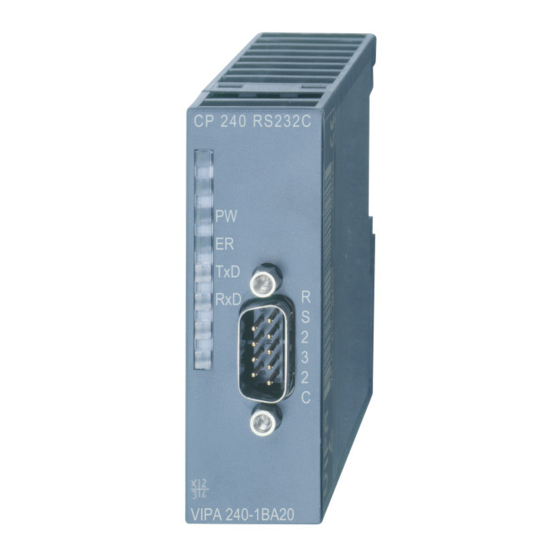
Chapter 4 CP 240 - serial Manual VIPA System 200V Structure Front view LED status indicator CP 240 RS232 CP 240 9pin serial D-type plug for RS232 240-1BA20 communication VIPA 240-1BA20 CP 240 CP 240 RS485 LED status indicator 240-1CA20... - Page 51 Manual VIPA System 200V Chapter 4 CP 240 - serial Components Power supply The communication processor receives power via the back plane bus. LEDs The communication processor is provided with 4 LEDs for the purpose of displaying the operating status. The following table depicts the description and the color of these LEDs.
- Page 52 Chapter 4 CP 240 - serial Manual VIPA System 200V CP240 Periphery RS232 cabling without hardware handshake shield CP240 Periphery RS232 cabling with hardware handshake shield shield HB97E - CP - Rev. 11/30...
- Page 53 Manual VIPA System 200V Chapter 4 CP 240 - serial • Logical states represented by voltage differences between the two cores RS485 interface of a twisted pair cable • Serial bus connection in two-wire technology using half duplex mode • High noise immunity •...
- Page 54 Chapter 4 CP 240 - serial Manual VIPA System 200V CP 240 Periphery RS485 cabling with Profibus RxD/TxD-P (B) RxD/TxD-P (B) cable RxD/TxD-N (A) RxD/TxD-N (A) Shield Periphery RxD/TxD-P (B) RxD/TxD-N (A) Periphery RxD/TxD-P (B) RxD/TxD-N (A) Pin 6 (P5V) of the isolated interfaces carries the isolated 5V supply with the RS485 cabling respective ground on pin 5 (M5V).
- Page 55 Manual VIPA System 200V Chapter 4 CP 240 - serial CP 240 Periphery RS422 cabling TxD-N (A) RxD-N (A) Send Receive TxD-P (B) RxD-P(B) RxD-N (A) TxD-N (A) Receive Send RxD-P (B) TxD-P (B) Shield Shield In the case of cables >50m you have to solder in a terminating resistor of approx. 330Ω...
-
Page 56: Ascii / Stx/Etx / 3964(R) / Rk512 - Basics
Chapter 4 CP 240 - serial Manual VIPA System 200V ASCII / STX/ETX / 3964(R) / RK512 - Basics ASCII data communication is one of the simple forms of data exchange ASCII that can be compared to a multicast/broadcast function. - Page 57 Manual VIPA System 200V Chapter 4 CP 240 - serial The 3964(R) procedure controls the data transfer of a point-to-point link 3964(R) between the CP 240 and a communication partner. The procedure adds control characters to the message data during data transfer. These control characters may be used by the communication partner to verify the complete and error free receipt.
- Page 58 Chapter 4 CP 240 - serial Manual VIPA System 200V The RK512 is an extended form of the 3964(R) procedure. The difference 3964(R) is that a message header is sent ahead of the message data. The header with RK512 contains data about the size, type and length of the message data.
- Page 59 Manual VIPA System 200V Chapter 4 CP 240 - serial Block check 3964R appends a Block check character to safeguard the transmitted data. The BCC-Byte is calculated by means of an XOR function over the character entire data of the message, including the DLE/ETX.
- Page 60 Chapter 4 CP 240 - serial Manual VIPA System 200V Message contents Every message has a header. Depending on the history of the message traffic, this header will contain all the required information. Structure of the output message Sample output message...
- Page 61 Manual VIPA System 200V Chapter 4 CP 240 - serial Structure of the input message Sample input message Normal message Reaction message Active partner Passive partner Byte Byte Message Reaction identifier Message header message flag Input command Data type Input...
-
Page 62: Ascii / Stx/Etx / 3964(R) / Rk512 - Communication Principle
The serial communication happens via the deployment of handling blocks in the PLC user application. These handling blocks may be downloaded via handling from ftp.vipa.de or received as part of the CD-ROM VIPA "ToolDemo". blocks Depending on the protocol the following handling blocks are used:... - Page 63 Manual VIPA System 200V Chapter 4 CP 240 - serial Tasks of the CPU The CPU has to split the telegram to send into blocks of 12Byte and transfer them via the back plane bus to the CP 240. In the CP 240 these blocks are assembled in the send buffer, proofed for completeness and then sent to the serial interface.
- Page 64 Chapter 4 CP 240 - serial Manual VIPA System 200V For the deployment of the CP 240 together with a System 200V CPU VIPA Software offers you a series of standard handler blocks that provide the software handshake handshake comfortable and easy.
-
Page 65: Ascii / Stx/Etx / 3964(R) / Rk512 - Parameterization
Manual VIPA System 200V Chapter 4 CP 240 - serial ASCII / STX/ETX / 3964(R) / RK512 - Parameterization General You may configure the CP 240 by means of 16Byte of configuration data. The structure of the parameter data depends on the selected protocol or. - Page 66 Chapter 4 CP 240 - serial Manual VIPA System 200V Structure of Byte Function Range of values Default parameter bytes parameters for STX/ETX Baud rate 00h: Default (9600Baud) 00h: 9600Baud 01h: 150Baud 02h: 300Baud 03h: 600Baud 04h: 1200Baud 05h: 1800Baud...
- Page 67 Manual VIPA System 200V Chapter 4 CP 240 - serial Structure of Byte Function Range of values Default parameter bytes for parameters 3964(R) / 3964(R) Baud rate 00h: Default (9600Baud) 00h: 9600Baud with RK512 01h: 150Baud 02h: 300Baud 03h: 600Baud...
- Page 68 Chapter 4 CP 240 - serial Manual VIPA System 200V Parameter description The data communication rate in Bit/s (Baud). Baud rate You may select one of the following values: 00h: Default (9600Baud) 01h: 150Baud 02h: 300Baud 03h: 600Baud 04h: 1200Baud...
- Page 69 Manual VIPA System 200V Chapter 4 CP 240 - serial Transfer For every character frame there are 3 data formats available. The data formats are different in the number of data bits, with or without parity bit parameter byte and number of stop bits.
- Page 70 Chapter 4 CP 240 - serial Manual VIPA System 200V Time delay after The delay time that must expire before a command is executed. The ZNA is specified in units of 20ms. command (ZNA) Range: 0 ... 255 Default: 0...
- Page 71 Manual VIPA System 200V Chapter 4 CP 240 - serial Delayed The delayed acknowledgment time defines the maximum time for the acknowledgment from the partner when the connection is being acknowledgment established. The QVZ is specified in units of 20ms.
-
Page 72: Modbus - Basics
Chapter 4 CP 240 - serial Manual VIPA System 200V Modbus - Basics Overview The Modbus protocol is a communication protocol that defines a hierarchic structure between a master and several slaves. Physically, Modbus transmits via a serial half-duplex core as point-to-point connection with RS232 or as multi-point connection with RS485. - Page 73 Manual VIPA System 200V Chapter 4 CP 240 - serial Modbus at the The CP 240 Modbus supports several operating modes that are described in the following: CP 240 from VIPA Modbus Master In Modbus Master operation you control the communication via your PLC user application.
-
Page 74: Modbus - Parameterization
Chapter 4 CP 240 - serial Manual VIPA System 200V Modbus - Parameterization Parameter Byte Function Range Default parameter structure at Modbus Baud rate 0h: 9600Baud 0h: 9600Baud 6h: 2400Baud 7h: 4800Baud 9h: 9600Baud Ah: 14400Baud Bh: 19200Baud Ch: 38400Baud... - Page 75 Manual VIPA System 200V Chapter 4 CP 240 - serial Parameter description The data communication rate in bit/s (Baud). You may select one of the Baud rate following values: 00h: Default (9600Baud) 06h: 2400Baud 07h: 4800Baud 09h: 9600Baud 0Ah: 14400Baud...
- Page 76 Chapter 4 CP 240 - serial Manual VIPA System 200V Data bits Number of data bits that represent a character. Parity The parity is depending on the value even or odd. For the purposes of the parity check, the information bits are expanded by the parity bit. The value of the parity bit ("0"...
-
Page 77: Modbus - Deployment
• Each 1 System 200V consisting of CPU 21x and CP 240 • Siemens SIMATIC Manager • Programming cable for MPI coupling (e.g. Green Cable from VIPA) • GSD-file VIPA_21x.gsd (V1.67 or higher) • VIPA handling blocks Fx000002_V120.zip or higher •... - Page 78 Chapter 4 CP 240 - serial Manual VIPA System 200V The following text describes the communication options between Modbus Communication master and Modbus slave with the following combination options: options • CP 240 Modbus Master ↔ CP 240 Modbus Slave Short •...
- Page 79 Manual VIPA System 200V Chapter 4 CP 240 - serial Master → → → → Modbus Master Slave Long The communication in master mode happens via data blocks deploying the CP 240 SEND-RECEIVE handling blocks. With the usage of a blockage you may transfer up to 250Byte user data.
- Page 80 Chapter 4 CP 240 - serial Manual VIPA System 200V Access to multiple At deployment of multiple slaves with RS485 there cannot occur bus conflict errors because the master may only communicate with one slave at slaves a time. The master sends a command telegram to the save specified via the address and waits for a certain time where within the slave may send its respond telegram.
-
Page 81: Modbus - Function Codes
0x and 1x gives you access to digital Bit areas and 3x and 4x to analog word areas. For the CP 240 from VIPA is not differentiating digital and analog data, the following assignment is valid: Bit area for master output data... - Page 82 Chapter 4 CP 240 - serial Manual VIPA System 200V Overview With the following Modbus function codes a Modbus master can access a Modbus slave: With the following Modbus function codes a Modbus master can access a Modbus slave. The description always takes place from the...
- Page 83 Manual VIPA System 200V Chapter 4 CP 240 - serial Code 01h: Read n Bits of master output area 0x Read n Bits 01h, 02h Code 02h: Read n Bits of master input area 1x Command telegram Slave address Function code...
- Page 84 Chapter 4 CP 240 - serial Manual VIPA System 200V Code 06h: Write 1 Word to master output area 4x Write 1 Word Command telegram Slave address Function code Address Value Check sum word word CRC/LRC 1 Byte 1 Byte...
-
Page 85: Modbus - Error Messages
Manual VIPA System 200V Chapter 4 CP 240 - serial Modbus - Error messages Overview At the communication at Modbus there are 2 error types: • Master doesn’t receive valid data • Slave responds with error message Master doesn’t If the slave doesn’t answer within the specified delay time or if a telegram is... -
Page 86: Modbus - Example
Requirements • 2 System 200V with CPU 21x and CP 240 • Programming cable for MPI connection (e.g. Green Cable from VIPA) • Serial cable to connect both CP 240 • Assemble a Modbus system, existing of master system, slave system Approach and connect them with the serial cable. - Page 87 Manual VIPA System 200V Chapter 4 CP 240 - serial Project structure The project has the following structure: The sample already contains the PLC program and the parameters for the Master project Modbus master. you only need to adjust the Modbus parameters.
- Page 88 Chapter 4 CP 240 - serial Manual VIPA System 200V PLC program The wanted Modbus commands are set via your PLC program. In the present sample the deployment of SEND and RECEIVE in the OB1 is shown. OB 1: CALL //"SEND"...
- Page 89 Manual VIPA System 200V Chapter 4 CP 240 - serial For the project engineering of the slave you only have to adjust the Modbus Slave project parameters. A PLC application is not required for the source and desti- engineering nation data are delivered in the master telegram.
- Page 90 Chapter 4 CP 240 - serial Manual VIPA System 200V Open the variable table Tabelle1 of the example project and switch to Send and receive online mode. telegram Send block DB10 Command telegram DB10.DBD 0 DW#16#05100000 → with Slave address 05h →...
- Page 91 Manual VIPA System 200V Chapter 4 CP 240 - serial Receive block with Slave does not answer to the master command error response If the slave does not respond within the specified timeout time, the master enters the following error message into the receive block: ERROR01 NO DATA.
-
Page 92: Technical Data
Chapter 4 CP 240 - serial Manual VIPA System 200V Technical data CP 240 RS232 Electrical Data VIPA 240-1BA20 Number of channels Voltage supply 5V via back plane bus Current consumption max. 150mA Status monitor via LED at the front side... - Page 93 Manual VIPA System 200V Chapter 4 CP 240 - serial CP 240 RS422/485 Electrical Data VIPA 240-1CA21 Number of channels Voltage supply 5V via back plane bus Current consumption max. 150mA Status monitor via LED at the front side Protocols...
- Page 94 Chapter 4 CP 240 - serial Manual VIPA System 200V Technical Data Protocols ASCII Telegram length max. 1024Byte Baud rate 150, 300, 600, 1200, 1800, 2400, 4800, 7200, 9600, 14400, 19200, 38400, 57600, 76800, 115200 Character delay time ZVZ 0 ... 5.1s in 20ms steps...
-
Page 95: Chapter 5 Cp 240 - Enocean
Manual VIPA System 200V Chapter 5 CP 240 - EnOcean Chapter 5 CP 240 - EnOcean This chapter contains information about the structure and the inclusion of Overview the communication processor CP 240 with EnOcean transceiver module. Content Topic Page Chapter 5 CP 240 - EnOcean ............ -
Page 96: System Overview
Chapter 5 CP 240 - EnOcean Manual VIPA System 200V System overview CP 240 EnOcean CP 240 EnOcean ANT. VIPA 240-1EA20 Order data Type Order number Description CP 240 EnOcean VIPA 240-1EA20 CP with EnOcean radio transceiver module TCM 120... -
Page 97: Basics
EnOcean uses IDs for the addressing. An ID is an compound of ID base and a freely configurable bit area. Since the EnOcean modules are delivered by VIPA with a different ID base with extensive projects it is recommended to note all ID base of the modules. So on error an module can be replaced and the appropriate ID base can be taken. -
Page 98: Fast Introduction
EnOcean communication. The CP 240 EnOcean is supplied with voltage via the back plane bus. For the internal communication the VIPA FCs are used. For the project engineering of the CP 240 EnOcean together with a CPU 21x in the Siemens SIMATIC Manager, the inclusion of the GSD VIPA_21x.gsd is... -
Page 99: Structure
Manual VIPA System 200V Chapter 5 CP 240 - EnOcean Structure • The communication processor has the order number VIPA 240-1EA20 Properties • 16Byte Parameter data • Voltage supply via back plane bus • The TCM 120 Transceiver module works at 868.3MHz. - Page 100 Chapter 5 CP 240 - EnOcean Manual VIPA System 200V Antennas The consignment doesn’t include an antenna but you may optional order a portable antenna or a magnetic socket antenna with 150cm cable. Both antennas are provided with a SMA plug. The coaxial build SMA plug (straight medium adaptor) is a miniature HF plug with threaded connector that excels by high HF denseness.
-
Page 101: Communication Principle
Manual VIPA System 200V Chapter 5 CP 240 - EnOcean Communication principle The CPU writes data via the back plane bus, which is to be sent, into the Send and receive according data channel. The communication processor enters them into a data ring buffer (2048Byte) and transmits them then via EnOcean. - Page 102 Chapter 5 CP 240 - EnOcean Manual VIPA System 200V For the deployment of the CP 240 together with a System 200V CPU VIPA Software offers handling blocks that enable a comfortable software handshake. handshake For the deployment of the CP 240 without handling blocks, the following text shows the functionality for transmitting and receiving data with an example.
-
Page 103: Example For Enocean Deployment
In the following example an EnOcean communication (send and receive) is build-up. Furthermore the sample illustrates how you may easily establish the control over communication processes by using the handling blocks. At need you may receive the example project from VIPA. Requirements The following components are required for the sample:... - Page 104 Chapter 5 CP 240 - EnOcean Manual VIPA System 200V Data blocks The example uses the following data blocks: DB10 Send data block Addr. Label Type Comment STRUCT +0.0 Sendefach STRUCT Send data block +0.0 RX_TX_Kennung BYTE 0B=RX/6B=TX +1.0 BYTE +2.0...
- Page 105 Manual VIPA System 200V Chapter 5 CP 240 - EnOcean DB11 Receive data block Addr. Label Type Comment STRUCT +0.0 Empfangsfach STRUCT Receive data block +0.0 RX_TX_Kennung BYTE 0B=RX/6B=TX +1.0 BYTE +2.0 Datenbyte3 BYTE Data byte 3 +3.0 Datenbyte2 BYTE Data byte 2 +4.0...
- Page 106 Chapter 5 CP 240 - EnOcean Manual VIPA System 200V PLC program The example already contains the PLC application and the hardware configuration. The following blocks are used: CALL FC 9 //Re-boot or Reset OB 1 :=256 //Address of the module TIMER_NR :=T2 :=M3.0...
- Page 107 Manual VIPA System 200V Chapter 5 CP 240 - EnOcean B#16#6B //allocate send data FC 101 "SEND_en_ocean".Empfangsfach.RX_TX_Kennung //send ID B#16#5 //ORG-ID "SEND_en_ocean".Empfangsfach.ORG B#16#2 "SEND_en_ocean".Empfangsfach.Datenbyte3 "SEND_en_ocean".Empfangsfach.Datenbyte2 "SEND_en_ocean".Empfangsfach.Datenbyte1 "SEND_en_ocean".Empfangsfach.Datenbyte0 "SEND_en_ocean".Empfangsfach.IDbyte2_3 W#16#3267 //Only the last 7Bit "SEND_en_ocean".Empfangsfach.IDbyte0_1 //are relevant for addr. //and are "ORed" in the "SEND_en_ocean".Empfangsfach.Status...
-
Page 108: Overview Of The Enocean Telegrams
Chapter 5 CP 240 - EnOcean Manual VIPA System 200V Overview of the EnOcean telegrams General structure The following table shows the general structure of an EnOcean telegram. Send and receive telegrams have the same structure. They only differ in the ID. - Page 109 Manual VIPA System 200V Chapter 5 CP 240 - EnOcean The TX_TELEGRAM and RX_TELEGRAM telegrams have the same Description of structure. The only difference is that a TX_TELEGRAM is identified by "3” ORG field in H_SEQ instead of "0” for an RX_TELEGRAM.
- Page 110 Chapter 5 CP 240 - EnOcean Manual VIPA System 200V Description of If ORG = 0x05 (Telegram from a PTM switch module) STATUS field Reserved RP_COUNTER Reserved (2 bit) Do not care (1 bit) T21=0 PTM type 1, T21=1 PTM type 2...
- Page 111 Manual VIPA System 200V Chapter 5 CP 240 - EnOcean If ORG = 0x05 and NU = 1 (N-message from a PTM switch module): Description of DATA_BYTE 3..0 DATA_BYTE2..0 always = 0 DATA_BYTE3 as follows: SRID (2 bit) Rocker ID, from left (A) to right (D): 0, 1,...
- Page 112 Chapter 5 CP 240 - EnOcean Manual VIPA System 200V If ORG = 0x07 (Telegram from a 4 Byte STM sensor): DATA_BYTE3 Value of third sensor analog input DATA_BYTE2 Value of second sensor analog input DATA_BYTE1 Value of first sensor analog input...
- Page 113 Manual VIPA System 200V Chapter 5 CP 240 - EnOcean Command Telegrams and Messages After a power-on, a hardware reset or a RESET command the TCM INF_INIT informs the user through several of these telegrams about the current status. The messages have the general syntax as shown. The information contained by the bytes marked as X should be decoded according to ASCII code.
- Page 114 Chapter 5 CP 240 - EnOcean Manual VIPA System 200V Standard message used to confirm that an action was performed correctly by the TCM. Bit 7 Bit 0 0xA5 0x5A 0x8B 0x58 ChkSum Standard error message response if after a TCT command the operation could not be carried out successfully by the TCM.
- Page 115 Manual VIPA System 200V Chapter 5 CP 240 - EnOcean SET_IDBASE With this command the user can rewrite its ID range base number. The most significant ID byte is IDBaseByte3. The information of the 25 most significant bits is stored in EEPROM.
- Page 116 Chapter 5 CP 240 - EnOcean Manual VIPA System 200V SET_RX_SENSITIVITY This command is used to set the TCM radio sensitivity. In LOW radio sensitivity, signals from remote transmitters are not detected by the TCM receiver. This feature is useful when only information from transmitters in the vicinity should be processed.
- Page 117 Manual VIPA System 200V Chapter 5 CP 240 - EnOcean SLEEP If the TCM receives the SLEEP command, it works in an energy-saving mode. The TCM will not wake up before a hardware reset is made or a WAKE telegram is sent via the serial interface.
- Page 118 Chapter 5 CP 240 - EnOcean Manual VIPA System 200V MODEM_ON Activates TCM modem functionality and sets the modem ID. An OK confirmation telegram is generated. The modem ID is the ID at which the TCM receives messages of type 6DT. The modem ID and modem status (ON/OFF) is stored in EEPROM.
- Page 119 Manual VIPA System 200V Chapter 5 CP 240 - EnOcean INF_MODEM_ Informs the user about the TCM current modem status. The information provided is the following: Modem status (ON or OFF) and modem ID STATUS stored. Modem state=0x01, modem ON Modem state=0x00, modem OFF Modem ID MSB= most significant modem ID byte.
- Page 120 Chapter 5 CP 240 - EnOcean Manual VIPA System 200V INF_SW_VER Informs the user about the current software version of the TCM. Bit 7 Bit 0 0xA5 0x5A Example: Version 1.0.1.16 0x8B 0x8C TCM SW Version Pos.1 = 1 TCM SW Version Pos.1 TCM SW Version Pos.2...
- Page 121 Manual VIPA System 200V Chapter 5 CP 240 - EnOcean ERR_MODEM_ When the TCM receives an original (not repeated) MDA telegram with the same modem ID as its own, it sends this message through the serial port DUP_ID and informs that at least 2 TCMs have the same modem ID. This is not necessarily a problem and may even be intended.
- Page 122 Chapter 5 CP 240 - EnOcean Manual VIPA System 200V ERR_TX_ When a radio telegram intended to be sent has an ID number outside the ID range, this error message is generated. The radio telegram is not IDRANGE delivered. Bit 7...
-
Page 123: Exchange Module And Set Id Base
Manual VIPA System 200V Chapter 5 CP 240 - EnOcean Exchange module and set ID base Overview Since the ID base of every module is different, you have in case of replacement the option to change the ID base of a module for up to 10 times by means of a SET_IDBASE telegram. - Page 124 Chapter 5 CP 240 - EnOcean Manual VIPA System 200V SET_IDBASE In case of replacement send a SET_IDBASE telegram with the following structure from your CPU to the module (transceiver). Use the address of the module you want to replace as new ID base:...
-
Page 125: Technical Data
Manual VIPA System 200V Chapter 5 CP 240 - EnOcean Technical data CP 240 EnOcean Electrical data VIPA 240-1EA20 Number of channels Power supply 5V via back plane bus Current consumption max. 120mA Power loss 0.75W External power supply Status indicator (LEDs) - Page 126 Chapter 5 CP 240 - EnOcean Manual VIPA System 200V 5-32 HB97E - CP - Rev. 11/30...
-
Page 127: Chapter 6 Cp 240 - M-Bus
Manual VIPA System 200V Chapter 6 CP 240 - M-Bus Chapter 6 CP 240 - M-Bus This chapter contains information about the assembly and the inclusion of Overview the CP 240 M-Bus for communication with energy and excise counters. Content... -
Page 128: System Overview
Chapter 6 CP 240 - M-Bus Manual VIPA System 200V System overview CP 240 M-Bus CP 240M-Bus M-Bus VIPA 240-1FA20 Order data Type Order No. Description CP 240 M-Bus VPA 240-1FA20 CP with M-Bus interface HB97E - CP - Rev. 11/30... -
Page 129: Basics
Manual VIPA System 200V Chapter 6 CP 240 - M-Bus Basics M-Bus The M-Bus system (Metering Bus) is an European standardized (DIN EN 1434-3) two-wire field bus for the excise data capturing. At this the data transfer happens serial via a polarity inversion secure two-wire core from slave systems (measuring devices) to a master system. -
Page 130: Fast Introduction
The CP 240 M-Bus is power supplied via the back plane bus. For the internal communication the VIPA FCs are used. For the project engineering of the CP 240 M-Bus together with a CPU 21x in the Siemens SIMATIC Manager, the inclusion of the GSD VIPA_21x.gsd is required. -
Page 131: Structure
Manual VIPA System 200V Chapter 6 CP 240 - M-Bus Structure • The communication processor has the order number VIPA 240-1FA20 Properties • Voltage supply via back plane bus • Up to 6 slaves may be connected • Standardized bus system acc. DIN EN 1434-3... -
Page 132: Communication Principle
Chapter 6 CP 240 - M-Bus Manual VIPA System 200V Communication principle Send and receive The CPU writes data via the back plane bus, which is to be sent into the according data channel. data The communication processor enters them into a ring buffer (2048Byte) and transmits them via M-Bus. - Page 133 Manual VIPA System 200V Chapter 6 CP 240 - M-Bus For the deployment of the CP 240 together with a System 200V CPU VIPA Software offers you a series of standard handling blocks that provide the software handshake handshake comfortable and easy.
-
Page 134: Overview Of M-Bus Telegrams
M-Bus. With the call of the VIPA handling blocks exclusively the following data (marked green) must be transferred, depending on the telegram. Here the sum of these bytes has to be set as length value. - Page 135 Manual VIPA System 200V Chapter 6 CP 240 - M-Bus Baud rate Every M-Bus telegram has to be prefixed with one byte that specifies the baud rate. The following baud rates are supported: Hex value Baud 2400 9600 If none of the mentioned values is entered in the 1 byte, 2400Baud are automatically used.
- Page 136 Chapter 6 CP 240 - M-Bus Manual VIPA System 200V FCB bit The FCB bit alternates at successful communication. An unchanging FCB summons the terminal device to send the last telegram again. The lack of an answer from a slave is accounted after 330 bit times plus 50ms. The master firstly assumes that an error occurred in the connection level.
- Page 137 Manual VIPA System 200V Chapter 6 CP 240 - M-Bus Master → Slave CI field Application Defined at Sending data EN1434-3 Select slave User group July ´93 Reset on application level User group March ´94 Synchronize slave Set baud rate 300 User group July ´93...
- Page 138 Chapter 6 CP 240 - M-Bus Manual VIPA System 200V The following examples show how a telegram is build-up from predefined Examples data and how the received telegram is stored in the data block. Assignment via DB Telegram via M-Bus...
-
Page 139: Example For M-Bus Deployment
In the following example a M-Bus communication (send and receive) is build-up. Furthermore the example shows how you may easily control the communication processes by using the handling blocks. At need you may receive the example project from VIPA. Requirements For the example, the following components are required:... - Page 140 Chapter 6 CP 240 - M-Bus Manual VIPA System 200V Data blocks The example uses the following data blocks: DB10 SEND data block Addr. Name Type Comment STRUCT +0.0 Sendefach STRUCT Send data block +0.0 Baudrate BYTE B8h=300, BBh=2400, BDh=9600 +1.0...
- Page 141 Manual VIPA System 200V Chapter 6 CP 240 - M-Bus PLC program The PLC application has the following structure: CALL //SYNCHRON_RESET :=256 //Module address TIMER_NR :=T8 //Delay time for CP :=M3.0 //CPU start complete NULL :=M3.1 //Internal flag RESET :=M3.2 //Initialize reset at CP STEUERB_S:=DB10.DBB260...
- Page 142 Chapter 6 CP 240 - M-Bus Manual VIPA System 200V FC 100 This function sends a request to a M-Bus participant and receives the answer. The transmit data has to be entered into DB 10 starting with data byte 4 before calling the function.
-
Page 143: Technical Data
Manual VIPA System 200V Chapter 6 CP 240 - M-Bus Technical data CP 240 with M-Bus interface Electrical Data VIPA 240-1FA20 Number of channels Number of connectable slaves Power supply 5V via back plane bus Current consumption max. 300mA External power supply... - Page 144 Chapter 6 CP 240 - M-Bus Manual VIPA System 200V 6-18 HB97E - CP - Rev. 11/30...
-
Page 145: Index
Manual VIPA System 200V Index Appendix A Index Examples........5-9 exchange module ....5-29 3964(R)........4-11 Fast introduction....... 5-4 with RK 512 ......4-12 Handling blocks ......5-4 LEDs......... 5-5 Parameter......... 5-4 A field.......... 6-10 set ID Base......5-29 ASCII .......... 4-10 Software handshake.... - Page 146 Index Manual VIPA System 200V Protocol........4-29 STEUERBIT (FC 8) ....3-9 RTU ........4-26 SYNCHRON_RESET (FC 9).. 3-10 Slave FETCH_RK512 (FC 2) ....3-12 Flow control ........ 4-23 Long ......4-27, 4-33 Short......4-27, 4-32 Slave respond......4-36 Green Cable ......... 3-6 Technical data ......
- Page 147 Manual VIPA System 200V Index RS485-Schnittstelle Overview......1-3, 1-5 Verkabelung ......4-8 Peripheral modules ....1-4 Profile rail ......... 2-2 Project engineering ....1-4 S/R_ALL_RK512 (FC 4) ..... 3-16 Reliability ........1-5 SEND (FC 0)......... 3-7 Removal ........2-7 SEND_RK512 (FC 3)....3-14 Safety Information ....
- Page 148 Index Manual VIPA System 200V M.Stich HB97E - CP - Rev. 11/30...
Need help?
Do you have a question about the System 200V CP 240 and is the answer not in the manual?
Questions and answers