Table of Contents
Advertisement
Advertisement
Table of Contents

Related Manuals for Tenmars TM-185


Summary of Contents for Tenmars TM-185
- Page 1 Temperature/Humidity Monitor TM-185 TM-185D User’s Manual HB2TM1850000...
-
Page 2: Table Of Contents
TM-185/TM-185D Table of Contents PREFACE ............2 CHARACTERISTICS ........2 GENERAL SPECIFICATIONS ......3 ELECTRICAL SPECIFICATION ......4 INSTRUMENT DESCRIPTION ......5 LED DESCRIPTION .......... 8 CLOCK AND DATE SETUP ......9 ALARM RANGE SETUP ......... 10 BATTERY REPLACEMENT ......12 EXTERNAL DC POWER ........ -
Page 3: Preface
TM-185/TM-185D 1 PREFACE Thank you for your patronage, please do read the operation instructions in details before you use this meter, so that operate correctly, make a machine give play to the best function. 2 CHARACTERISTICS LED display. ... -
Page 4: General Specifications
TM-185/TM-185D 3 General Specifications Display: Double rows LED, humidity MAX reading 999,and temperature MAX reading 1999. Temperature sensor: Diode. Humidity Sensor: Capacitor Sensor. Sampling: 1 times/second. Power: AC to DC Adapter. (9V/1A). Backup Power:9V battery、 NEDA 1604、IEC 6F22 or JIS 006P(Only data logger use). -
Page 5: Electrical Specification
TM-185/TM-185D 4 Electrical Specification Measurement Range: Humidity: 5%~95%. Temprature:-20.0°C~60.0°C /-4.0°F~140.0°F. Temperature Accuracy:±1.0°C/±1.8°F (-5.0°C ~40.0°C /23°F~104°F);other ±2.0°C /3.6°F. Humidity Accuracy: ±2.5%RH(at 25°C,10%RH~90%RH). ±5.0%RH(at 25°C,<10%RH,>90%RH). Note1: If you require more accurate we can do it according to your requirement. -
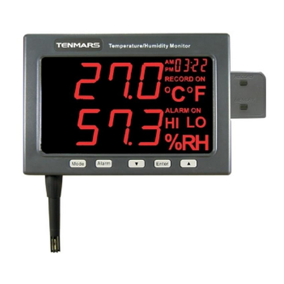
Page 6: Instrument Description
TM-185/TM-185D 5 Instrument description... - Page 7 TM-185/TM-185D...
- Page 8 TM-185/TM-185D 1. Temperature & Humidity sensor 2. Time Set Button Alarm Set Button 4. °C /°F Set Button/Down Button 5. Enter Button 6. Hold Button/UP Button 7. LED Display 8. Data Logger Box (optional) 9. Data Logger Box interface (-) 10.
-
Page 9: Led Description
TM-185/TM-185D 6 LED description Temperature reading value Humidity reading value Time reading value Time unit Data logger symbol Temperature unit Alarm symbol HI symbol LO symbol 10. Humidity unit... -
Page 10: Clock And Date Setup
TM-185/TM-185D 7 Clock and Date setup Push “ ” button into time clock and date setup. Push “ ”button to select option to adjust Push “ ”or “ ” button to change the digit. Push “... -
Page 11: Alarm Range Setup
TM-185/TM-185D 8 Alarm Range Setup Push “ ” button into alarm setup LED will display ALARM ON。If you just reading alarm setup please push “ ” button again LED will display ALARM OFF. First push “ ” button into alarm range setup,LED display show “... - Page 12 TM-185/TM-185D If test Temperature or Humidity exceed set range, buzzer were bleep, at this time socket output sin wave signal at 2000Hz,terminal blocks were short.
-
Page 13: Battery Replacement
TM-185/TM-185D 9 Battery replacement WARNING If the LO Battery LED were turn on, please replace the battery immediately Turn off the instrument. Open the battery cover and remove the battery. Replace with four-9V NEDA 1604, IEC 6F22 or JIS 006P size battery. -
Page 14: External Dc Power
TM-185/TM-185D 10 External DC Power Voltage External AC to DC adapter: (8~14V Max) Socket:pin Positive, Ground Casing External Diameter 6.3mm internal Diameter 2.0 mm Safety Precaution For cleaning the instrument use a soft dry cloth. Never use a wet cloth, solvents or water, etc. -
Page 15: Software Installation (Tm-185D)
TM-185/TM-185D 12 Software installation (TM-185D) Please put the CD in the PC that will be connected to this meter. Please select the USB driver that will be installed, such as E:\TM-185D\PL-2303 Driver Installer.exe (windows 2000 SP4/windows XP SP2), click twice on... - Page 16 TM-185/TM-185D Select the SETUP.EXE i.e., E:\TM-185D\SETUP.EXE and installs the desktop icon Tack out the CD from PC after completed the installation of the desktop icon.
- Page 17 TM-185/TM-185D Use the USB cable to connect the meter and computer according to the drawing. Select the desktop icon (TM-185) and click twice on left key of the mouse to run the procedure.
-
Page 18: Maintenance
TM-185/TM-185D 13 Maintenance Do not use the meter in an environment with severe change; do not store the unit in an environment with high temperature, high humidity, and high vibration Take battery off if the meter has not been used for a long period of time ... -
Page 19: End Of Life
TM-185/TM-185D 14 End of life Caution: this symbol indicates that equipment and its accessories shall be subject to a separate collection and correct disposal 15 Auto Stores Data Push “ ” button into time clock and date setup. ... -
Page 20: Single Data Memory
TM-185/TM-185D 16 Single data memory Push Record button (in TM-185D) each time to store the display reading and memory location in memory. 17 Viewing logged Data Push Memory button (in TM-185D) into view logged data mode,push Memory button again exit view logged data mode ... - Page 21 TENMARS ELECTRONICS CO., LTD 6F, 586, RUI GUANG ROAD, NEIHU, TAIPEI 114, TAIWAN. E-mail: service@tenmars.com http://www.tenmars.com...
Need help?
Do you have a question about the TM-185 and is the answer not in the manual?
Questions and answers