Sign In
Upload
Download
Table of Contents
Contents
Add to my manuals
Delete from my manuals
Share
URL of this page:
HTML Link:
Bookmark this page
Add
Manual will be automatically added to "My Manuals"
Print this page
×
Bookmark added
×
Added to my manuals
Manuals
Brands
Westomatic Manuals
Vending machines
Eco Encore
Technical manual
Westomatic Eco Encore Technical Manual
Hide thumbs
1
2
3
4
5
6
7
8
9
10
11
12
13
14
15
16
17
18
19
20
21
22
23
24
25
26
27
28
29
30
31
32
33
34
35
36
37
38
39
40
41
42
43
44
45
46
47
48
49
50
51
52
53
54
55
56
57
58
59
60
61
62
63
64
65
66
67
68
69
70
71
72
73
74
75
76
77
78
79
80
81
82
83
84
85
86
87
88
89
90
91
92
93
94
95
96
97
98
99
100
101
102
103
104
105
106
107
108
109
110
111
112
113
114
115
116
117
118
119
120
121
122
123
124
125
126
127
128
129
130
131
132
133
134
135
136
137
138
139
140
141
142
143
144
145
146
147
148
149
150
page
of
150
Go
/
150
Contents
Table of Contents
Bookmarks
Table of Contents
Table of Contents
Safety Notice
Specifications
Drink Selection Codes
External Features
Installations & Commissioning
How to Set up and Use Machine Facilities
Using the External Keypad
Programming
Machine Set-Up Addresses
Programming Commands
11. Drinks Setup
Drinks Setup
Table of Multiple Field Parameters
Example 1
Example 2
Drink Selection Set up Address
Single Cup
Hot Water
Still Water
Carbonated Water
Syrup 1
Syrup 2
Instant 1
Instant 2
Instant 5/Soup/Topping/Cold Powder
Instant Espresso
Espresso Choc
Creamichoc
Chocolate
Freshbrew Tea/Coffee
Bean to Cup Regular Coffee
FB/BTC Espresso
Double Inst/Fb/Btc Espresso
Inst/Fb/Btc Cappuccino
Inst/Fb/Btc Café Latte
Quick Reference Addresses
Freshbrew Brewer Unit
Bean to Cup Drinks Setup
Carbonated Water
Chilled Water
Nestle Accolade
Moving Dispense Head
Microprocessor System & Simm Logic
Error Codes
Fault Finding
Machine Maintenance
Connector Outputs
Parts Order Process
Recommended Spare Parts List
Parts List Diagrams
Step Guide for Bean to Cup Drinks
Advertisement
Quick Links
1
How to Set up and Use Machine Facilities
2
Programming
3
Drinks Setup
4
Error Codes
5
Fault Finding
Download this manual
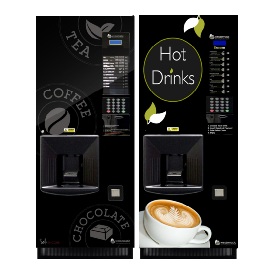
Eco Encore & Solo Encore
Technical Manual
Table of
Contents
Previous
Page
Next
Page
1
2
3
4
5
Advertisement
Chapters
Table of Contents
2
11. Drinks Setup
52
Table of Contents
Need help?
Do you have a question about the Eco Encore and is the answer not in the manual?
Ask a question
Questions and answers
Related Manuals for Westomatic Eco Encore
Vending machines Westomatic Easy 6000 Operator And Installation Manual
(41 pages)
Vending machines Westomatic EASY 6000 Technical Manual
(58 pages)
Vending machines Westomatic Elevate Quartz Series Technical Information
(53 pages)
Vending machines Westomatic ELEVATE QUARTZ Operating Instructions Manual
Cold drinks vending machine (77 pages)
Vending machines Westomatic EVOLVE Technical Manual
(57 pages)
Vending machines Westomatic EVOLVE Installation Manual
(4 pages)
Vending machines Westomatic EVOLVE Fitting Plinths
(7 pages)
Vending machines Westomatic EVOLVE Manual
Replace screen fascia (24 pages)
Vending machines Westomatic EVOLVE Installing
Screen media (7 pages)
Vending machines Westomatic EVOLVE Manual
Change button dispense volume (7 pages)
Vending machines Westomatic EVOLVE Manual
Adjusting water/ flavour dispense volume (17 pages)
Vending machines Westomatic Evolve Manual
(4 pages)
Vending machines Westomatic SHMOO Cleaning Manual
(8 pages)
Vending machines Westomatic Elevate Quick Start Manual
(6 pages)
Vending machines Westomatic Snackpoint Quattro Manual
(134 pages)
Vending machines Westomatic Primo Compact Installation Manual
(13 pages)
This manual is also suitable for:
Solo encore
Table of Contents
Print
Rename the bookmark
Delete bookmark?
Delete from my manuals?
Login
Sign In
OR
Sign in with Facebook
Sign in with Google
Upload manual
Upload from disk
Upload from URL


Need help?
Do you have a question about the Eco Encore and is the answer not in the manual?
Questions and answers