MSA ALTAIR 5 Operating Manual
Multi gas detector
Hide thumbs
Also See for ALTAIR 5:
- Instruction manual (245 pages) ,
- Operating manual (221 pages) ,
- Quick start card (2 pages)

Related Manuals for MSA ALTAIR 5


Summary of Contents for MSA ALTAIR 5
- Page 1 Operating Manual ALTAIR 5 – Multi Gas Detector Manufactured by P.O. Box 427, Pittsburgh, Pennsylvania 15230, USA Order No.: 10094176/00 Y-HLS...
- Page 2 WARNING Read this manual carefully before using the instrument. The instrument will perform as designed only if it is used and maintained in accordance with the manufacturer's instruction. Otherwise, it could fail to perform as designed and persons who rely on this instrument for their safety could sustain serious personal injury or death.
-
Page 3: Table Of Contents
Instrument Setup ................29 3.5. Data Logging ................. 37 3.6. Function Tests on the Instrument ..........37 3.7. Safe LED..................38 3.8. Calibration Check ................38 3.9. Calibration ..................38 3.10. Instrument Shutdown ..............41 ALTAIR 5 - Operating Manual... - Page 4 Options from Main Page..............59 7.4. Password Protected Options............60 7.5. Menu Sequence from Main page ..........61 7.6. Calibration Sequence ..............63 7.7. Calibration Options................ 64 7.8. Alarm Options ................65 7.9. Instrument Options ................ 67 ALTAIR 5 - Operating Manual...
-
Page 5: Instrument Safety
Instrument Safety 1.1. Correct Use The ALTAIR 5 Multigas Detector is for use by trained and qualified per- sonnel. It is designed to be used when performing a hazard assessment to: Assess potential worker exposure to combustible and toxic gases •... -
Page 6: Safety And Precautionary Measures To Be Adopted
• (available sensors see Section 6). Check function (see section 3.6) each day before use. MSA recommends carrying out a routine inspection prior to use each day before use. Perform calibration check (see section 3.8) before each day's use to verify proper instrument operation. - Page 7 100 % LEL or 5.00 %vol CH , and an explosion hazard exists. Move away from hazardous area immediately. Do not use the ALTAIR 5 Multigas Detector to test for combustible or • toxic gases in the following atmospheres as this may result in erroneous...
- Page 8 Do not replace batteries in hazardous area. Observe proper battery maintenance Use only battery chargers made available by MSA for use with this instrument; other chargers may damage the battery pack and the unit. Dispose of in accordance with local health and safety regulations.
-
Page 9: 1.3.1 Warranty
Two years* ClO2, NH3, HCN, NO2, PH3, SO2 sensors One year* For extended warranty offerings please contact MSA 1.3.1 Warranty This warranty does not cover filters, fuses, etc. Certain other accessories not specifically listed here may have different warranty periods. This warranty is valid only if the product is maintained and used in accordance with Seller's instructions and/or recommendations. -
Page 10: Description
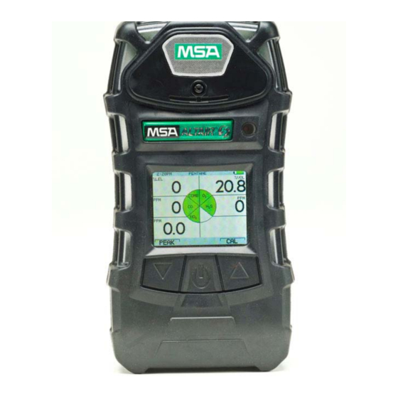
Communication ] Button Sensor Inlets 10 Belt Clip Pump Cap 11 Charging Connection Horn 12 Screws Display 13 Pump inlet ] Button 14 Filter The instrument monitors gases in ambient air and in the workplace. ALTAIR 5 - Operating Manual... - Page 11 The alarm levels for the individual gases are factory-set and can be changed through the instrument Setup Menu. These changes can also be made through MSA Link Software. Ensure that the latest version of the MSA Link software has been downloaded from MSA’s website www.msanet.com. ALTAIR 5 - Operating Manual...
-
Page 12: Device Hardware Interfaces
GREEN user that the instrument is ON and operating under the conditions defined in section 3.7. This option can be turned OFF through the MSA Link software. The red LEDs are visual indications of an alarm condition or any type of error in the instrument. -
Page 13: On-Screen Indicators
CO Sensor – Indicates the CO Indicates current time 1:30 PM channel use. Indicates the name of next S Sensor – Indicates the page – here a PEAK reading PEAK S channel use. mode ALTAIR 5 - Operating Manual... - Page 14 2.3.3 Battery Life Indicator The battery condition icon continuously displays in the upper right-hand corner of the display. A bar represents the charging level of the battery, if the battery is empty only the battery icon outline remains. ALTAIR 5 - Operating Manual...
- Page 15 • alarm sounds • alarm LEDs flash • display shows " " • LOW BATTERY instrument continues to operate until the instrument is turned OFF • or battery shutdown occurs. ALTAIR 5 - Operating Manual...
- Page 16 NOTE: Allow very hot or cold instruments to stabilize for one hour at room temperature before attempting to charge. Minimum and maximum ambient temperature to charge the instrument • is 10°C/50°F and 35°C/95°F, respectively. For best results, charge the instrument at room temperature (23°C). • ALTAIR 5 - Operating Manual...
-
Page 17: Viewing Optional Displays
This page shows the lowest level of oxygen recorded by the instrument since turn-ON or since the MIN reading was reset. To reset the MIN readings: (1) Access the MIN page. ] button. (2) Press the [ ALTAIR 5 - Operating Manual... - Page 18 (15 minutes x 35 ppm) = 35 ppm 15 minutes 10-minute exposure of 35 ppm and 5 minutes exposure of 15 ppm: (10 minutes x 35 ppm) + (5 minutes x 5 ppm) = 25 ppm 15 minutes ALTAIR 5 - Operating Manual...
- Page 19 4-hour exposure of 50 ppm and 4-hour exposure of 100 ppm: (4 hours x 50 ppm) + (4 hours x 100 ppm) = 75 ppm 8 hours 12-hour exposure of 100 ppm: (12 hours x 100 ppm) = 150 ppm 8 hours ALTAIR 5 - Operating Manual...
-
Page 20: Sensor Missing Alarm
The alarm can be silenced for five seconds by pressing • the [ ] button; no other pages can be viewed. If there is a sensor error at startup, the instrument shuts OFF in • 60 seconds. ALTAIR 5 - Operating Manual... -
Page 21: Monitoring Toxic Gases
• the alarm message displays and flashes in combination with the • corresponding gas concentration enters an alarm state • alarm sounds • alarm LEDs flash • a vibration alarm triggers • ALTAIR 5 - Operating Manual... -
Page 22: Monitoring The Oxygen Concentration
(altitude) or extreme changes in ambient temperature. It is recommended that an oxygen calibration be performed at the temperature and pressure of use. Be sure that the instrument is in known fresh air before performing a calibration. ALTAIR 5 - Operating Manual... -
Page 23: Monitoring Combustible Gases
A combustible gas reading of "XXX” indicates the atmosphere is above 100 % COMB or 5.00 %vol CH and an explosion hazard exists. Move away from contaminated area immediately. In such cases, the instrument LockAlarm feature activates. ALTAIR 5 - Operating Manual... -
Page 24: Operation
The oxygen sensor has built-in temperature compensation. However, if temperature shifts dramatically, the oxygen sensor reading may shift. Zero the instrument at a temperature within 86°F (30°C) of the work site temperature for the least effect. ALTAIR 5 - Operating Manual... -
Page 25: Turning On And Fresh Air Setup
Alarm setpoints TWA Alarm • Settings for calibration cylinder • Current date • Last calibration date • CAL due date • Sensor warm-up period • Fresh Air Setup option. • Refer to flowchart in Appendix, Section 7.1 ALTAIR 5 - Operating Manual... - Page 26 Last Cal Date The Last Cal date displays in a month, day and year format. CAL Due This display option can be set by MSA Link software. If this option is not set, this screen is not displayed. Sensor Warm Up The time for sensor Warm Up is shown by a progressing bar.
- Page 27 The calibration check is required to verify span accuracy. Failure to follow this warning can result in serious personal injury or death. SETUP Vol% COMB FRESH AIR SETUP ? Figure 3-1 Fresh Air Setup ALTAIR 5 - Operating Manual...
-
Page 28: Measurement Mode (Normal Operation)
OPERATION If this option is enabled through the MSA Link software, the instrument displays a blinking " ", prompting the user to FRESH AIR SETUP? perform a Fresh Air Setup: (1) Press the [ ] button to bypass the Fresh Air Setup. -
Page 29: Instrument Setup
Incorrect password: instrument returns to the Main Page. • Correct password: user can set the instrument options. • The password can be changed with a PC through the MSA Link software. The following options are available by pressing the [ ] and [ ] buttons: Calibration options - see Section 3.4.1... - Page 30 With this confirmation the instrument automatically moves to the next cylinder setting. (3) Repeat the sequence for changing the required settings for all necessary gas values. After the last setting is performed, the instrument returns to the Calibration Options menu. ALTAIR 5 - Operating Manual...
- Page 31 ALARM OPTIONS ALARM OPTIONS The Alarm Options Menu allows the user to: enable/disable the Vibrate • enable/disable the Horn • enable/disable the Alarm LED • enable/disable the Motion Alert Feature and • set Sensor Alarms. • ALTAIR 5 - Operating Manual...
- Page 32 • TWA Alarm. • (1) Press the [ ] button to enter Sensor Alarm setup. LOW Alarm Setup screen displays. • SETUP Vol% 19.5 COMB LOW ALARM ABORT CHANGE NEXT Figure 3-5 Sensor Alarm Setup ALTAIR 5 - Operating Manual...
- Page 33 OFF. When turned ON, the combustible high alarm is latching. The combustible alarm can be silenced momentarily by pressing the [ ] button. However, if the gas concentration causing the alarm is still present, the unit will go back into alarm. ALTAIR 5 - Operating Manual...
- Page 34 • Backlight Options. • Press the [ ] button go to next page (EXIT MENU) • the [ ] button to go previous page (ALARM OPTIONS) • the [ ] button to enter setup. • ALTAIR 5 - Operating Manual...
- Page 35 Other operations such as changing the gas type (Methane, Butane, Propane etc. for the combustible sensor) and units (ppm to mg/m ) are only possible using the MSA Link software. (3) Change status by pressing the [ ] or [ ] button.
- Page 36 • Setting Stealth Mode (1) Press the [ ] button to change mode. (2) Press the [ ] button to go to the next page or the [ ] button to return to previous page. ALTAIR 5 - Operating Manual...
-
Page 37: Data Logging
3.5. Data Logging Connecting Instrument to PC (1) Switch ON the ALTAIR 5 and align the Datalink Communication port on the ALTAIR 5 to the IR interface of the PC. (2) Start the MSA Link software on the PC and start connection by clicking the connect icon. -
Page 38: Safe Led
Perform this calibration check before each day’s use for each installed sensor. (1) Turn ON the ALTAIR 5 Multigas Detector in clean, fresh air. (2) Verify that readings indicate no gas is present. (3) Attach regulator (supplied with calibration kit) to the cylinder. - Page 39 ZERO CALIBRATION PASS 1:30 PM SETUP ” PASS “ ZERO CALIBRATION ZERO CALIBRATION FAIL ”. FAIL Only if the instrument passes 1:30 PM SETUP • 15.0 the zero calibration the SPAN COMB screen displays. SPAN CALIBRATION ? ALTAIR 5 - Operating Manual...
- Page 40 SETUP completed, the instrument COM B displays either “ SPAN CALIBRATION SPAN CALIBRATION PASS 1:30 PM SETUP ” PASS COMB “ SPAN CALIBRATION SPAN CALIBRATION FAIL ” FAIL The instrument returns to • Measuring mode. ALTAIR 5 - Operating Manual...
-
Page 41: 3.10. Instrument Shutdown
FOR SHUTDOWN Figure 3-10 Instrument Shutdown The instrument displays a blinking " HOLD BUTTON FOR " and a progress bar shows the user how much longer to SHUTDOWN hold the button to complete the shutdown routine. ALTAIR 5 - Operating Manual... -
Page 42: Maintenance
WARNING Repair or alteration of the ALTAIR 5 Multigas Detector, beyond the proce- dures described in this manual or by anyone other than a person authorized by MSA, could cause the instrument to fail to perform properly. -
Page 43: Troubleshooting
Contact MSA ERROR RAM Battery warning repeats LOW BATTERY every 15 seconds. Battery is completely BATTERY discharged. ALARM Charge instrument Instrument Remove from service as does not battery soon as possible and turn ON recharge battery ALTAIR 5 - Operating Manual... -
Page 44: Verifying Pump Operation
If liquid is sucked into the instrument, readings will be inaccurate and instrument could be damaged. We recommend the use of an MSA sample probe (P/N 10042621, 10042622, 10040589, or equivalent) containing a special membrane filter, permeable to gas but impermeable to water, to prevent such an occurrence. -
Page 45: Replacing The Battery
Battery pack (1) Unscrew the two captive screws on the rear of the instrument. (2) Pull the battery pack out of the instrument by gripping the sides and lifting it up and away from the instrument. ALTAIR 5 - Operating Manual... -
Page 46: Live Maintenance Procedure - Replacing And Adding A Sensor
To add a sensor to an instrument that is not already equipped with a full array of sensors, remove the sensor plug from in front of the formerly unused sensor housing. ALTAIR 5 - Operating Manual... - Page 47 Insert the combustible sensor by placing it in the left-hand side of • the sensor holder.Ensure groove in combustible sensor is aligned with notch in sensor slot. If a sensor is not to be installed, ensure that a sensor plug is • installed properly in place. ALTAIR 5 - Operating Manual...
-
Page 48: Cleaning The Instrument
86°F (18 °C and 30 °C). After storage, always recheck instrument calibration before use. 4.7. Shipment Pack the instrument in its original shipping container with suitable padding. If the original container is unavailable, an equivalent container may be substituted. ALTAIR 5 - Operating Manual... -
Page 49: Technical Specifications/Certifications
Oxygen: Electrochemical sensor methods Toxic gases Electrochemical sensor Standard two years. Extended options available Warranty (see full warranty for specific limitations). Measuring Combustible range 0-100% LEL 0-200 ppm 0-999 ppm 0-25 % Vol. 0-5.00% CH4 ALTAIR 5 - Operating Manual... -
Page 50: Factory-Set Alarm Thresholds
TECHNICAL SPECIFICATIONS/CERTIFICATIONS Measuring range 0-20.0 ppm 0-200 ppm 0-100 ppm 0-5.00 ppm 0-30.0 ppm 0-20.0 ppm 0-1.00 ppm *check with MSA for sensor availability 5.2. Factory-set Alarm thresholds HIGH Sensor STEL alarm alarm COMB 10 % LEL 20 % LEL... - Page 51 0.3 ppm 3.75 ppm 10.0 ppm 0.5 ppm 17.5 ppm 0.80 ppm 0.10 ppm 0.90 ppm 10.0 ppm 4.5 ppm 20.0 ppm This instrument is not approved for use in atmospheres containing >21 % oxygen. ALTAIR 5 - Operating Manual...
-
Page 52: Certifications
Ex ia S (Zone O) IIC T4 Australia Ambient temperature: 122°F European Community The product ALTAIR 5 complies with the following directives, standards or standardized documents: Directive 94/9/EC (ATEX) II 2G Ex ia d IIC T4 -20 °C ≤ Ta ≤ +50 °C... -
Page 53: Performance Specification
However, if range temperature 3 minutes shifts (extended dramatically, the temperature oxygen sensor range) reading may shift. Zero the instrument at a temperature within 86°F (30 °C) of the work place temperature for the least effect.) ALTAIR 5 - Operating Manual... - Page 54 Ammonia 0 - 5.0 ppm 0.05 ppm PH Phosphine 0 - 30.0 ppm 0.5 ppm HCN Hydrogen Cyanide 0 - 20.0 ppm 0.1 ppm Cl Chlorine 0 - 1.00 ppm 0.02 ppm ClO Chlorine Dioxide ALTAIR 5 - Operating Manual...
-
Page 55: Order Information
Universal Pump Probe, North America 10046528 Universal Pump Probe, Europe 10047596 Calibration Assembly Regulator, 0.25 LPM, Model RP 467895 Regulator, Combination, 0.25 LPM, Model RP 711175 Demand Regulator 710288 IR USB dongle (Datalog) 10082834 Infrared Datalogging Software 10088099 ALTAIR 5 - Operating Manual... - Page 56 Sensor bracket assembly with pump 10088609 (includes vibrator motor) Sensor bracket assembly (includes vibrator motor) 10088523 Kit, pump cap replacement 10095051 Printed circuit board assembly, ALTAIR 5 10078703 Kit, replacement, CO-H S, O , COMB sensors 10095052 Alkaline battery pack (includes belt clip)
-
Page 57: Appendix - Flow Charts
(Show SW version) Sensor Missing Sens miss Alarm Low Alarm High Alarm Gas Type Show Date TWA Alarm STEL Alarm Last Cal Show Last enable? Cal Date Show Cal Cal Due enable? Sensor Warmup FAS? Enabled ALTAIR 5 - Operating Manual... -
Page 58: Normal Operation
7.2. Normal Operation Startup sequence Turn On FAS? FAS CAL Display Pass/Fail Main Page Message Press Press Peak Reading Auto Calibration Page Hold simultaneously for 2 seconds Menu Password prompt ALTAIR 5 - Operating Manual... -
Page 59: Options From Main Page
APPENDIX – FLOW CHARTS 7.3. Options from Main Page Main Page Turn OFF Hold 4 seconds Hold Press Calibration 3 seconds Peak Page Page Hold simultaneously for 2 seconds Menu Page ALTAIR 5 - Operating Manual... -
Page 60: Password Protected Options
7.4. Password Protected Options Password prompt Password Main Page correct? Options to Select Alarm Calibration Instrument Main Page Options Options Options ALTAIR 5 - Operating Manual... -
Page 61: Menu Sequence From Main Page
Press Peak Reset Main Page Min Page Press Press Min Reset Main Page Press STEL Page Press Press STEL Reset Main Page Press TWA Page Press Press TWA Reset Main Page Press To date page ALTAIR 5 - Operating Manual... - Page 62 Date Page Press Main Page Press Last Cal Date Press Main Page Press Cal Date Press Main Page Press Motion Alert Press Press Press Toggle Motion Alert On/Off ALTAIR 5 - Operating Manual...
-
Page 63: Calibration Sequence
APPENDIX – FLOW CHARTS 7.6. Calibration Sequence Measure Page Calibration Zero? Display Pass/Fail Pass? Message Display Pass/Fail Message Special Case Special Case Span? Display Pass/Fail Pass? Message Display Pass/Fail Single Channel Message Calibration ALTAIR 5 - Operating Manual... -
Page 64: Calibration Options
7.7. Calibration Options Calibration Options Modify Cal Gas Settings Calibration Due Show Last Cal Date at Startup (Enable/ Disable) Password Protect Calibration (Enable/ Disable) Go to Main Menu ALTAIR 5 - Operating Manual... -
Page 65: Alarm Options
APPENDIX – FLOW CHARTS 7.8. Alarm Options Alarm Options Vibrator (Enable/Disable) Horn (Enable/Disable) Alarm LEDs (Enable/Disable) Motion Alert (Enable/Disable) Sensor Alarms ALTAIR 5 - Operating Manual... - Page 66 Go to Menu Page Alarm for sensors 0-5 Modify STEL Modify STEL Alarm Go to Menu Page Alarm for sensors 0-5 Modify TWA Modify TWA Alarm Go to Menu Page Alarm for sensors 0-5 Go to Menu Page ALTAIR 5 - Operating Manual...
-
Page 67: Instrument Options
APPENDIX – FLOW CHARTS 7.9. Instrument Options Instrument Options Stealth Mode Sensor Setup Operating Beep Language Setup Contrast Setup Time Setup Backlight Options Datalog Option Go to Main Menu ALTAIR 5 - Operating Manual... - Page 68 ALTAIR 5 - Operating Manual...
Need help?
Do you have a question about the ALTAIR 5 and is the answer not in the manual?
Questions and answers