
Related Manuals for MSA GM FL5000


Summary of Contents for MSA GM FL5000
- Page 1 Operating Manual FL5000 Multi-Spectrum Flame Detector Order No.: 10238682/01 Print Spec: 10000005389 (EO) CR: 800000064609 MSAsafety.com...
- Page 2 Otherwise, it could fail to perform as designed, and persons who rely on this device could sustain serious injury or death. The warranties made by MSA with respect to the product are voided if the product is not installed and used in accordance with the instructions in this manual.
-
Page 3: Table Of Contents
Contents Safety Regulations Quick Start Instructions Device Overview Features Applications Bluetooth Connectivity Principles of Operation LED Operation Mode Definitions Continuous Optical Path Monitoring - COPM Circuitry Test Mode Initiation Window Heater Operation Installation Unpacking Equipment Required Tools Detector Location Guidelines Detector Mounting and Installation Field Wiring Procedure Terminal Connections Switch Selectable Options... -
Page 4: Safety Regulations
• Repair or alteration of the device beyond the procedures described in the user guide or by anyone other than a person authorized by MSA, could cause the unit to fail to perform properly. Use only genuine MSA replacement parts when performing any maintenance procedures described in the user guide. - Page 5 • This product incorporates Bluetooth wireless technology. The Bluetooth word mark and logos are registered trademarks owned by Bluetooth SIG, Inc., and any use of such marks by MSA is under license. Other trademarks and trade names are those of their respective owners.
- Page 6 1 Safety Regulations However, there is no guarantee that interference will not occur in a particular installation. If this equipment does cause harmful interference to radio or television reception, which can be determined by turning the equipment off and on, the user is encouraged to try to correct the interference by one or more of the following measures: •...
-
Page 7: Quick Start Instructions
2 Quick Start Instructions Quick Start Instructions Figure 1 FL5000 Quick Start Insert 1. Electrical Connection a. Loosen the captive screws (A) located on the Optical Housing Assembly. b. Pull the Optical Housing Assembly from the Base Housing Assembly to separate, gently rocking from side to side if necessary to loosen the connector's grip. - Page 8 2 Quick Start Instructions 2. Mounting a. Choose a location for mounting, ensuring that all proper requirements for safety and use are met. See Detector Mounting and Installation for a list of mounting location concerns/warnings. b. Assemble the bracket by connecting the center clamp bit to the bracket with the included screw, washer and nut set.
- Page 9 2 Quick Start Instructions Figure 4 Bracket Assembly Figure 5 Field Terminations 3. Power a. Ensure that all wiring is correct and unit is safe to power up. b. Connect unit to a 24 VDC power source. c. The unit will go through a power up delay of approximately 15 seconds. This includes LED activity. See Powering the FL5000 for additional information.
-
Page 10: Device Overview
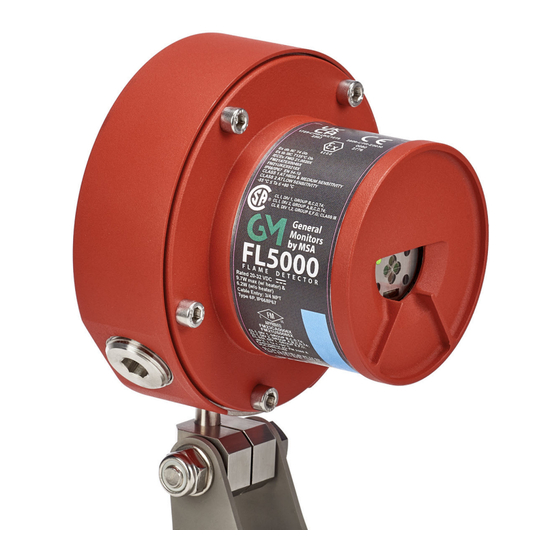
3 Device Overview Device Overview The FL5000 is a Multi-Spectrum Flame Detector. The FL5000 employs state-of-the-art infrared (IR) detectors and an advanced flame detection algorithm leveraging a sophisticated artificial neural network (ANN) based signal processing to produce a system that is highly immune to false alarms caused by lightning, sunlight reflection, arc-welding, hot objects, and other sources of radiation. -
Page 11: Bluetooth Connectivity
3 Device Overview Bluetooth Connectivity NOTE: Bluetooth is enabled by factory default. If Bluetooth is not needed, it can be deactivated by opening the unit and setting the Bluetooth DIP switch to disabled. This switch is inside the FL5000, see 5.7 Switch Selectable Options. - Page 12 3 Device Overview Activating Bluetooth Module from different switches. * TL105: For Non-Latching alarm setup only, BT will be activated after the successful test lamp process completed (after TL105 test lamp alarm). FL5000 Multi-Spectrum Flame Detector...
-
Page 13: Principles Of Operation
4 Principles of Operation Principles of Operation The FL5000 is a discriminating Multi-Spectrum Flame Detector, which makes use of infrared sensors for different IR wavelengths and characteristics. This combination provides a flame detection system, which is highly immune to false alarms. -
Page 14: Continuous Optical Path Monitoring - Copm Circuitry
4 Principles of Operation Device Status Standard Mode Green LED Yellow LED Low Voltage, Code or Data, Checksum Fault Red LED Blue LED Green LED 0.9s ON, 0.1s OFF Yellow LED Test Mode Activated Red LED Blue LED Green LED Alternate blinking slowly (1 Hz) Yellow LED Test Mode Warning Red LED... -
Page 15: Test Mode Initiation
4 Principles of Operation Test Mode Initiation NOTE: The FL5000 will not detect a flame while in Test Mode. The FL5000 has the ability to initiate a special Test Mode, which enables the user to test the response of the unit without the use of a flame source. - Page 16 4 Principles of Operation Recharging Instructions Insert the charging plug into the receptacle. Complete recharging takes 3.5 hours minimum. NOTE: Charging must be carried out in a non-hazardous area. The charging receptacle is located inside the housing adjacent to the ON button. To gain access, it is necessary to unscrew the knurled plug from the body of the unit. The plug is secured to the ON button by a safety strap to keep it from being lost.
- Page 17 4 Principles of Operation Figure 8 Test Lamp Flashing Option (Auto-Detection) When the unit is in Operational Mode, the FL5000 recognizes the Test Lamp as a trigger to activate the Test Mode. Within 5-8 seconds of the Test Lamp flashing, the FL5000 will detect the simulated flame source, drop the analog output to 1.5 mA (3.5 mA with HART and small HART current disabled), and change the LED flashing to indicate “Test Mode Activated”...
- Page 18 4 Principles of Operation After 2 seconds in Test Mode (Phase 2): • the FL5000 indicates an Instant Alarm condition by: ○ setting the analog output to 16 mA ○ changing the LED flashing to indicate “Test Mode Instant Alarm" ○...
- Page 19 4 Principles of Operation 4.3.2 HART Command For Test Mode Initiation via HART Command, please refer to the FL5000 HART Manual (PN 10242587). FL5000 Multi-Spectrum Flame Detector...
- Page 20 4 Principles of Operation 4.3.3 Modbus Command or Grounding Test Wire Figure 9 Grounding of Test Wire or Modbus Command Options Momentary grounding of a test wire or the Modbus test-mode-enable command causes the FL5000 to enter Test Mode. Initiation of Test Mode is indicated by the analog output dropping to 1.5 mA (3.5 mA with HART and small HART current disabled) and LED flashing in sequence shown in 4.1 LED Operation Mode Definitions.
-
Page 21: Window Heater Operation
4 Principles of Operation • the FL5000 goes into Phase 4: ○ indicates 1.5 mA (3.5 mA with HART and small HART current disabled) at the analog output ○ changes the LED flashing to indicate “Test Mode Activated" After 4.25 minutes in Phase 4: •... -
Page 22: Installation
If any damage has occurred or there is any discrepancy in the order, please contact MSA. NOTE: Each FL5000 is completely tested at the factory; however, a system check is required upon initial start-up to guarantee system integrity. - Page 23 5 Installation 5.3.1 Optical Sensitivity Range Sensitivity Setting Specified Range The distance at which the detector will respond to a flame is a function of the intensity of that flame. The maximum High 310 ft (95 m) distance is 310 ft (95 m) for an n-heptane fire with a Medium 140 ft (43 m) surface area of 1 ft...
- Page 24 5 Installation 5.3.2 Detector Field of View Each FL5000 Flame Detector has a maximum range of 310 feet (95 m). The FOV has its vertex at the center of the detector. Horizontal FOV is measured in the horizontal plane going through the center axis of the detector, and vertical FOV is measured in the vertical plane going through the same axis.
-
Page 25: Detector Mounting And Installation
5 Installation The following fuels have been tested and their applicable field of view charts and sensitivity details can be viewed in Certifications. Heptane JP4 (2' x 2') Gasoline JP5 (1' x 1') Methanol JP5 (2' x 2') Methane JP8 (1' x 1') Butane JP8 (2' x 2') Propane... - Page 26 5 Installation Figure 11 Detector Mounting and Installation Figure 12 Dimensional Drawing FL5000 Multi-Spectrum Flame Detector...
-
Page 27: Field Wiring Procedure
5 Installation Field Wiring Procedure Figure 13 FL5000 Housing 1. Loosen the captive screws (A) located on the Optical Housing Assembly. 2. Pull the Optical Housing Assembly from the Base Housing Assembly to separate, gently rock from side to side if necessary to loosen the connector's grip. -
Page 28: Terminal Connections
5 Installation Terminal Connections Figure 15 Wire-Strip Lengths All wire connections are made through the ¾ inch (1.9 cm) NPT openings in the Base Housing to the Terminal Block. The Terminal Block is located in the Base Housing Assembly and accepts 14 AWG (2.08 mm ) to 22 AWG (0.33 mm stranded or solid-core wire. - Page 29 5 Installation The connections are to the single pole, double throw (SPDT) SUSTAINED ALARM relay. SUSTAINED ALARM output is time delayed for 0, 8, 10, or 14 seconds. This time delay can be set by Modbus (RS-485) or the user selectable dipswitch 5.7 Switch Selectable Options.
- Page 30 5 Installation DC Control Voltage 117 VAC Control Voltage Protection circuit for relay contacts when switching a Protection circuitt for relay contacts when switching an DC load. AC load Refer to the figure in 5.6.1 Sustained Alarm Relay for all relay connections. 5.6.4 Fault Relay Terminal Block Connection Point Block Name Normally Energized...
- Page 31 5 Installation 5.6.7 Alarm Test Terminals Terminal Connection Block Setting Block Point Name TEST_ Test By connecting one contact of a DPST, normally open, momentary Term 4 Mode switch to each of the P1 terminal 4 and P2 terminal 4 simultaneously and the other contact to (GND), the user can Relay Term 4...
- Page 32 5 Installation 5.6.8 Analog Output Terminal Block Connection Point Block Name Setting Term 7 0 - 20 mA Analog Output The 0 to 20 mA output is a current signal that corresponds to the following: Analog Output HART (1.25 mA)* HART (3.5 mA) HART Disabled/OFF Startup...
- Page 33 5 Installation 5.6.10 Power The table below shows the power connections for the FL5000. The supply voltage range is 20 to 32 VDC at the detector (low voltage is detected at 18.5 VDC). Terminal Block Connection Point Block Name Setting Term 8 +24 Vin +24V...
-
Page 34: Switch Selectable Options
5 Installation Switch Selectable Options All settings on the FL5000 are selected via a dipswitch on the Power/Relay board or via Modbus (overrides switch settings). To set these options: 1. Remove the detector head from the Base Assembly and locate the dipswitch per the Dipswitch Location figure in 5.7.1 Time Delay Settings 2. - Page 35 5 Installation Position High Sensitivity Medium Sensitivity Low Sensitivity 0 Sec Alarm Time Delay 8 Sec Alarm Time Delay 10 Sec Alarm Time Delay 14 Sec Alarm Time Delay Sustained Alarm Non-Latching Sustained Alarm Latching Instant Alarm Non-Latching Instant Alarm Latching Sustained Alarm Normal De-Energized Sustained Alarm Normal Energized Instant Alarm Normal De-Energized...
-
Page 36: Powering The Fl5000
5 Installation Powering the FL5000 After connecting to a 24 VDC power source, the unit will go through the following on power up: • all four LEDs (red, yellow, blue, green) will blink in a series for 15 seconds • the unit will output an analog signal of 0 mA (3.5 mA with HART or 1.25 mA for HART with small current enabled) •... -
Page 37: Maintenance
Once correctly installed, the unit requires very little maintenance other than regular sensitivity checks and cleaning of the window. MSA recommends that a schedule be established and followed. Do not remove the electronics from the housing. Doing so will void the equipment’s warranty. -
Page 38: Sensitivity Check
6 Maintenance Sensitivity Check To verify that each detector is functioning correctly, an MSA Test Lamp and/or the ALARM TEST function per 5.6.7 Alarm Test Terminals should be used. Refer to 8.3 Accessories for Test Lamp details. Storage The FL5000 should be stored in a clean, dry area and within the temperature and humidity ranges found in 8.2.4... -
Page 39: Troubleshooting
Troubleshooting This section is intended to be a guide to correcting problems, which may arise in the field. MSA should be contacted for assistance if the corrective action listed does not eliminate the problem. Defective units should be returned to MSA for repair with a complete written description of the problem. -
Page 40: Final Assembly
7 Troubleshooting Final Assembly Figure 21 FL5000 Cross-Section View Sapphire Window Mounting Pin EMI Screen Modular Power Board Heater Ring Board Modular Communication Board Label Modular Processor Board O-Ring Analog Board Base Housing Optical Housing Assembly Field Wiring Board FL5000 Multi-Spectrum Flame Detector... -
Page 41: Learn More
MSA, the Safety Company warrants that these products will be free from mechanical defect or faulty workmanship for a period of five (5) years from the date of delivery, provided it is maintained and used in accordance with MSA's instructions and/or recommendations. -
Page 42: Specifications
8 Learn More Specifications 8.2.1 System Specifications Typical Response Time: 10 seconds, see 9 Certifications for FM Approval response times Field of View*: ±30° @ 210 ft (64 m), ±45° @ 110 ft (34 m), 90° total field of view 310 ft (95 m), 140 ft (43 m), and 70 ft (21 m) for high, medium, and low sensitivities, Sensitivity: respectively. - Page 43 8 Learn More 8.2.5 Electrical Specifications* Nominal supply voltage: 24 VDC (5.7 W with Heater 'OFF', 8.9 W with Heater 'ON') Range: 20 to 32 VDC 6.2 W (heater ‘OFF’) Maximum power consumption: 9.7 W (heater ‘ON’) Spectral range: 2 – 5 microns (IR) Maximum output signal load: 600 Ω...
-
Page 44: Accessories
8 Learn More Accessories Additional information is available upon request for any of the accessories below. 8.3.1 Test Lamp with Charger - PN TL105-1001 Due to the advanced discrimination of the FL5000, the TL105 Test Lamp was developed. The Test Lamp is a battery operated, rechargeable, test source specifically designed to test General Monitors’... -
Page 45: Rain Guard - Pn 712004-1
Air Curtain - PN 712881-1 The Model AC45 Compressed Air Curtain accessory protects the optical surfaces of your MSA IR flame detector. It uses positive air pressure to create a protective air curtain that prevents contaminants from settling onto the detector’s optical surfaces. -
Page 46: Fl4000H Upgrade Kit - Pn 10242703
8 Learn More 8.3.6 FL4000H Upgrade Kit - PN 10242703 Figure 26 FL4000H Upgrade Kit Quick Start Insert FL5000 Multi-Spectrum Flame Detector... -
Page 47: Certifications
9 Certifications Certifications Approvals subject to change without notice and may differ based on configuration, part number and/or country. Contact Customer Service or check the approval label on the product for specific approval information. Region Certification Agency Primary Standard Details United States Performance FM 3260 See Section... -
Page 48: Flame Performance Fm3260, Ulc-Ord-C386, En
9 Certifications Flame Performance FM3260, ULC-ORD-C386, EN 54-10 9.1.1 On-Axis Performance The table below shows the response characteristics of the FL5000 in the presence of false alarm sources. The table below shows the FM approval characteristics. Fuel Fire Size Fire Distance ft (m), Average Response Time (seconds) by Sensitivity Setting for Instant Alarm : Sustained Alarm High... - Page 49 9 Certifications EN54-10 Classification The table below shows the FM Approved EN54-10 classifications and extended distance claims. Sensitivity Classification Fuel Size Distance ft Avg. Response Time (seconds) High Class 1 n-Heptane/ 330mm x 330mm x 50mm deep 210 (64) Instant Alarm: 6 Sustained Alarm: 7 (≥25 m) Toluene...
-
Page 50: Field Of View Performance
9 Certifications 9.1.2 Field of View Performance The FM Approved FL5000 Flame Detector has a maximum range of 310 feet (95 m). The FOV has its vertex at the center of the detector. Horizontal FOV is measured in the horizontal plane going through the center axis of the detector, and vertical FOV is measured in the vertical plane going through the same axis. - Page 51 9 Certifications Gasoline (1' x 1') Horizontal High 0° 160' 140' + 30° 160' 140' - 30° 160' 140' + 45° - 45° Vertical High 0° 160' 140' + 30° 160' 140' - 30° 160' 140' - 45° FL5000 Multi-Spectrum Flame Detector...
- Page 52 9 Certifications Methanol (1' x 1') Horizontal High 0° 160' + 30° 160' - 30° 160' + 45° - 45° Vertical High 0° 160' + 30° 160' - 30° 160' - 45° FL5000 Multi-Spectrum Flame Detector...
- Page 53 9 Certifications Methane (32" Plume) Horizontal High 0° 180' + 30° 180' - 30° 180' + 45° - 45° Vertical High 0° 180' + 30° 180' - 30° 180' - 45° FL5000 Multi-Spectrum Flame Detector...
- Page 54 9 Certifications Butane (32" Plume) Horizontal High 0° 160' + 30° 160' - 30° 160' + 45° - 45° Vertical High 0° 160' + 30° 160' - 30° 160' - 45° FL5000 Multi-Spectrum Flame Detector...
- Page 55 9 Certifications Propane (32" Plume) Horizontal High 0° 180' + 30° 180' - 30° 180' + 45° 120' - 45° 120' Vertical High 0° 180' + 30° 180' - 30° 180' - 45° 120' FL5000 Multi-Spectrum Flame Detector...
- Page 56 9 Certifications Ethane (32" Plume) Horizontal High 0° 190' + 30° 190' - 30° 190' + 45° - 45° Vertical High 0° 190' + 30° 190' - 30° 190' - 45° FL5000 Multi-Spectrum Flame Detector...
- Page 57 9 Certifications Ethanol (1' x 1') Horizontal High 0° 170' 100' + 30° 170' 100' - 30° 170' 100' + 45° - 45° Vertical High 0° 170' 100' + 30° 170' 100' - 30° 170' 100' - 45° FL5000 Multi-Spectrum Flame Detector...
- Page 58 9 Certifications Crude Oil (1' x 1') Horizontal High 0° 140' 115' + 30° 140' 110' - 30° 140' 110' + 45° - 45° Vertical High 0° 140' 110' + 30° 140' 110' - 30° 140' 110' - 45° FL5000 Multi-Spectrum Flame Detector...
- Page 59 9 Certifications Ethylene Glycol (1' x 1') Horizontal High 0° 120' + 30° 100' - 30° 100' + 45° - 45° Vertical High 0° 100' + 30° 100' - 30° 100' - 45° FL5000 Multi-Spectrum Flame Detector...
- Page 60 9 Certifications Isopropanol (1' x 1') Horizontal High 0° 180' 120' + 30° 180' 120' - 30° 180' 120' + 45° - 45° Vertical High 0° 180' 120' + 30° 180' 120' - 30° 180' 120' - 45° FL5000 Multi-Spectrum Flame Detector...
- Page 61 9 Certifications Diesel (1' x 1') Horizontal High 0° 140' + 30° 140' - 30° 140' + 45° - 45° Vertical High 0° 140' + 30° 140' - 30° 140' - 45° FL5000 Multi-Spectrum Flame Detector...
- Page 62 9 Certifications JP4 (1' x 1') Horizontal High 0° 160' 100' + 30° 160' 100' - 30° 160' 100' + 45° - 45° Vertical High 0° 160' 100' + 30° 160' 100' - 30° 160' 100' - 45° FL5000 Multi-Spectrum Flame Detector...
- Page 63 9 Certifications JP4 (2' x 2') Horizontal High 0° 170' 110' + 30° 170' 110' - 30° 170' 110' + 45° - 45° Vertical High 0° 170' 110' + 30° 170' 110' - 30° 170' 110' - 45° FL5000 Multi-Spectrum Flame Detector...
- Page 64 9 Certifications JP5 (1' x 1') Horizontal High 0° 150' 120' + 30° 150' 120' - 30° 150' 120' + 45° - 45° Vertical High 0° 150' 120' + 30° 150' 120' - 30° 150' 120' - 45° FL5000 Multi-Spectrum Flame Detector...
- Page 65 9 Certifications JP5 (2' x 2') Horizontal High 0° 200' 160' + 30° 170' 150' - 30° 170' 150' + 45° - 45° Vertical High 0° 170' 150' + 30° 170' 150' - 30° 170' 150' - 45° FL5000 Multi-Spectrum Flame Detector...
- Page 66 9 Certifications JP8 (1' x 1') Horizontal High 0° 170' 120' + 30° 170' 120' - 30° 170' 120' + 45° - 45° Vertical High 0° 170' 120' + 30° 170' 120' - 30° 170' 120' - 45° FL5000 Multi-Spectrum Flame Detector...
- Page 67 9 Certifications JP8 (2' x 2') Horizontal High 0° 180' 135' + 30° 180' 135' - 30° 180' 135' + 45° - 45° Vertical High 0° 180' 135' + 30° 180' 135' - 30° 180' 135' - 45° FL5000 Multi-Spectrum Flame Detector...
- Page 68 9 Certifications Jet Fuel A (1' x 1') Horizontal High 0° 180' 120' + 30° 170' 120' - 30° 170' 120' + 45° - 45° Vertical High 0° 170' 120' + 30° 170' 120' - 30° 170' 120' - 45° FL5000 Multi-Spectrum Flame Detector...
- Page 69 9 Certifications Jet Fuel A (2' x 2') Horizontal High 0° 170' 130' + 30° 170' 130' - 30° 170' 130' + 45° - 45° Vertical High 0° 170' 130' + 30° 170' 130' - 30° 170' 130' - 45° FL5000 Multi-Spectrum Flame Detector...
- Page 70 9 Certifications Marina Fuel (1' x 1') Horizontal High 0° 190' 170' + 30° 190' 170' - 30° 190' 170' + 45° - 45° Vertical High 0° 190' 170' + 30° 190' 170' - 30° 190' 170' - 45° FL5000 Multi-Spectrum Flame Detector...
- Page 71 9 Certifications Kerosene (1' x 1') Horizontal High 0° 160' 140' + 30° 160' 140' - 30° 160' 140' + 45° - 45° Vertical High 0° 160' 140' + 30° 160' 140' - 30° 160' 140' - 45° FL5000 Multi-Spectrum Flame Detector...
- Page 72 9 Certifications Xylene (1' x 1') Horizontal High 0° 150' + 30° 150' - 30° 150' + 45° - 45° Vertical High 0° 150' + 30° 150' - 30° 150' - 45° FL5000 Multi-Spectrum Flame Detector...
- Page 73 9 Certifications MEK (1' x 1') Horizontal High 0° 170' 140' + 30° 170' 140' - 30° 170' 140' + 45° - 45° Vertical High 0° 170' 140' + 30° 170' 140' - 30° 170' 140' - 45° FL5000 Multi-Spectrum Flame Detector...
- Page 74 9 Certifications Wood (6" x 6") Horizontal High 0° + 30° - 30° + 45° - 45° Vertical High 0° + 30° - 30° - 45° FL5000 Multi-Spectrum Flame Detector...
- Page 75 9 Certifications Cardboard (6" x 6") Horizontal High 0° + 30° - 30° + 45° - 45° Vertical High 0° + 30° - 30° - 45° FL5000 Multi-Spectrum Flame Detector...
-
Page 76: False Alarm Stimuli Performance
9 Certifications 9.1.3 False Alarm Stimuli Performance The FM approved FL5000 detector is immune to a variety of false alarm sources. Below are representative samples of detector response in the presence of false stimuli. As a worst case condition the high sensitivity variation was tested to demonstrate no false alarm result without fuel n-Heptane (1' x 1'), equivalent to 0.3 x 0.3 meters. - Page 77 9 Certifications False Alarm Source False Alarm n-Heptane (1' x 1') (Modulated and Un-modulated) Distance from Fuel Distance Response Time for Detector from Detector Instant Alarm: ft (m) ft (m) Sustained Alarm (seconds) 150W Shielded Mercury Lamp 10 (3) 80 (24) 6 : 7 500W Shielded Halogen Lamp, Un-modulated 10 (3)
Need help?
Do you have a question about the GM FL5000 and is the answer not in the manual?
Questions and answers