Table of Contents
Advertisement
Quick Links
SFP Managed Switch Eco Quick Start Guide
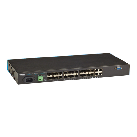
Provides (20) Gigabit Ethernet SFP and (4) Gigabit
Ethernet Combo RJ-45/SFP connections.
Order toll-free in the U.S.: Call 877-877-BBOX (outside U.S. call 724-746-5500)
Customer
FREE technical support 24 hours a day, 7 days a week: Call 724-746-5500 or fax 724-746-0746
Support
Mailing address: Black Box Corporation, 1000 Park Drive, Lawrence, PA 15055-1018
Information
Web site: www.blackbox.com • E-mail: info@blackbox.com
BLACK BOX
LGB5124A
®
Advertisement
Table of Contents

Related Manuals for Black Box LGB5124A


Summary of Contents for Black Box LGB5124A
- Page 1 Order toll-free in the U.S.: Call 877-877-BBOX (outside U.S. call 724-746-5500) Customer FREE technical support 24 hours a day, 7 days a week: Call 724-746-5500 or fax 724-746-0746 Support Mailing address: Black Box Corporation, 1000 Park Drive, Lawrence, PA 15055-1018 Information Web site: www.blackbox.com • E-mail: info@blackbox.com...
- Page 2 Disclaimer Black Box Network Services shall not be liable for damages of any kind, including, but not limited to, punitive, consequential or cost of cover damages, resulting from any errors in the product information or specifications set forth in this document and Black Box Network Services may revise this document at any time without notice.
- Page 3 FCC and IC RFI Statements/CE Mark Federal Communications Commission and Industry Canada Radio Frequency Interference Statements This equipment generates, uses, and can radiate radio-frequency energy, and if not installed and used properly, that is, in strict accordance with the manufacturer’s instructions, may cause inter ference to radio communication. It has been tested and found to comply with the limits for a Class A computing device in accordance with the specifications in Subpart B of Part 15 of FCC rules, which are designed to provide reasonable protection against such interference when the equipment is operated in a commercial environment.
- Page 4 Safety Instructions Safety Instructions CAUTION: Circuit devices are sensitive to static electricity, which can damage their delicate electronics. Dry weather conditions or walking across a carpeted floor may cause you to acquire a static electrical charge. To protect your device, always: •...
- Page 5 NOM Statement Instrucciones de Seguridad (Normas Oficiales Mexicanas Electrical Safety Statement) 1. Todas las instrucciones de seguridad y operación deberán ser leídas antes de que el aparato eléctrico sea operado. 2. Las instrucciones de seguridad y operación deberán ser guardadas para referencia futura. 3.
-
Page 6: Table Of Contents
Table of Contents Table of Contents 1. Specifications ..................................7 2. Overview ....................................9 2.1 Introduction ...................................9 2.2 What’s Included ................................9 2.3 Front and Side Panels of the Switch ..........................9 2.4 Switch Architecture ..............................10 2.5 Network Management Options ........................... 10 2.6 Operation of Web-based Management ........................10 3. -
Page 7: Specifications
Chapter 1: Specifications 1. Specifications 1.1 Physical Characteristics Aggregate Bandwidth 48 Gbps for the LGB5124A switch Buffer Architecture 1392 KB on-chip frame buffer Network Interface Ports 1-20: SFP connector; Ports 21-24: RJ-45 connector/(100/1000M) SFP; 10BASE-T: RJ-45 (100-ohm, UTP cable; Category 3 or better);... - Page 8 Chapter 1: Specifications 1.3 Management Features Approvals Emissions: EN55022 (CISPR 22) Class A EN 61000-3; FCC Class A; CE Mark; Immunity: EN 61000-4-2/3/4/5/6/8/11; EN 55024 In-Band Management SSH/SSL, Telnet, SNMP, or HTTP Software Loading HTTP, TFTP in-band, Console out-of-band Standards IEEE 802.3 =>...
-
Page 9: Overview
It’s easy to deploy and configure, providing stable and quality performance network services. 2.2 What’s Included Your package should contain the following items. If anything is missing or damaged, contact Black Box Technical Support at 724-746-5500 or info@blackbox.com. • Gigabit SFP Managed Switch Eco •... -
Page 10: Switch Architecture
First, configure your device’s Ethernet interface to be in the same subnet as the LGB5124A switch. Then, you can browse to the LGB5124A. For example, if you type http://192.168.1.1, it will show the login screen and ask you to input a username and password to login and authorize access to the switch. -
Page 11: Hardware Description
Chapter 3: Hardware Description 3. Hardware Description 3.1 1000BASE-T Ports The switch has 10/100/1000BASE-T RJ-45 ports. All RJ-45 ports support automatic MDI/MDI-X operation, auto-negotiation, and IEEE 802.3x auto-negotiation of flow control, so the switch automatically selects the optimum data rate and transmission. 3.2 SFP Transceiver Slots The switch supports Small Form Factor Pluggable (SFP) transceiver slots on ports 1 to 24. -
Page 12: Power Supply Sockets
Chapter 3: Hardware Description Figure 3-2. System Status LEDs on the front panel. Table 3-2. System Status LEDs Color Status PWR AC Green Lights when power is on. PWR DC Green Lights when power is on. Green/ Amber Blinks when system is booting. Lights when system is coming up. -
Page 13: Installing The Switch
Chapter 4: Installing the Switch 4. Installing the Switch 4.1 Selecting a Site NOTE: The switch can be mounted in a standard 19-inch equipment rack (via the included rackmount kit). Follow the guidelines below when choosing a location. The site should: •... -
Page 14: Equipment Checklist
• (1) AC power cord To download the user manual, visit www.blackbox.com and enter LGB5124A in the search bar, then download the user’s manual, or download the user’s manual from ftp://ftp.blackbox.com/manuals/L/LGB5124A_USER_rev1.pdf. WARNING: The SFP/SFP+ modules are Class 1 laser devices. Avoid direct eye exposure to the beam coming from the transmit port. - Page 15 Chapter 4: Installing the Switch To rackmount devices: (Optional) Step 1. Attach the brackets to the device using the screws provided in the mounting accessory. Figure 4-3. Attaching the brackets. Step 2. Mount the device in the rack (via the rackmount kit), using four rackmounting screws (not provided). Be sure to secure the lower rackmounting screws first to prevent the brackets from bending from the weight of the switch.
-
Page 16: Desktop Or Shelf Mounting
You can install or remove an SFP/SFP+ module from an SFP/SFP+ slot without having to power off the switch. Use only compatible SFPs (see Table 4-1). Table 4-1. Compatible Black Box SFPs. Table 4-1. Compatible Black Box SFPs. Part Number Product Name LFP401–LFP404... -
Page 17: Connecting To An Ac Power Source
Chapter 4: Installing the Switch Figure 4-6. Inserting an SFP transceiver into a slot. To install an SFP transceiver, do the following: Step 1. Consider network and cabling requirements to select an appropriate SFP transceiver type. Step 2. Insert the transceiver with the optical connector facing outward and the slot connector facing down. NOTE: SFP transceivers are keyed so they can only be installed in one orientation. -
Page 18: Connecting To A Dc Power Source
Chapter 4: Installing the Switch 4.7 Connecting to a DC Power Source You can plug or remove a DC power cable through the DC terminal block from an external 48-VDC power source. Figure 4-8. Insert the DC power cable into the DC terminal block to power on this switch. Step 1. -
Page 19: Connectivity Rules
Chapter 4: Installing the Switch WARNING: When selecting a fiber SFP device, make sure that it can function at a temperature that is not less than the recommended maximum operational temperature of the product. You must also use an approved Laser SFP transceiver. -
Page 20: 1000Base-T Cable Requirements
Chapter 4: Installing the Switch 4.11 1000BASE-T Cable Requirements All Category 5 UTP cables that are used for 100BASE-TX connections should also work for 1000BASE-T, providing that all four wire pairs are connected. However, we recommend that for all critical connections, or any new cable installations, you use Category 5e or Category 6 cable. - Page 21 NOTES 724-746-5500 | blackbox.com Page 21...
- Page 22 NOTES 724-746-5500 | blackbox.com Page 22...
- Page 23 NOTES 724-746-5500 | blackbox.com Page 23...
- Page 24 About Black Box Black Box provides an extensive range of networking and infrastructure products. You’ll find everything from cabinets and racks and power and surge protection products to media converters and Ethernet switches all supported by free, live 24/7 Tech support available in 30 seconds or less.
Need help?
Do you have a question about the LGB5124A and is the answer not in the manual?
Questions and answers