WEG CFW300 Quick Installation Manual
Micro drive
Hide thumbs
Also See for CFW300:
- User manual (125 pages) ,
- Programming manual (159 pages) ,
- Quick start manual (4 pages)
Advertisement
Quick Links
Quick Installation Guide
CFW300 Micro Drive
1 SAFETY INSTRUCTIONS
This quick installation guide contains the basic information necessary to commission the CFW300. It has
been written to be used by qualified personnel with suitable training or technical qualification for operating
this type of equipment. The personnel shall follow all the safety instructions described in this manual
defined by the local regulations. Failure to comply with the safety instructions may result in death, serious
injury, and/or equipment damage.
2 SAFETY WARNINGS IN THE MANUAL
NOTE!
It is not the intention of this guide to present all the possibilities for the application of the
CFW300, as well as WEG cannot take any liability for the use of the CFW300 which is not
based on this guide.
For further information about installation, full parameter list and recommendations, visit the
website www.weg.net.
DANGER!
The procedures recommended in this warning have the purpose of protecting the user
against death, serious injuries and considerable material damage.
ATTENTION!
The procedures recommended in this warning have the purpose of avoiding material damage.
NOTE!
The information mentioned in this warning is important for the proper understanding and
good operation of the product.
High voltages are present.
Components sensitive to electrostatic discharge.
Do not touch them.
Mandatory connection to the protective ground (PE).
Connection of the shield to the ground.
3 PRELIMINARY RECOMMENDATIONS
DANGER!
Always disconnect the main power supply before touching any electrical component
associated to the inverter. Several components can remain charged with high voltages or
remain in movement (fans) even after the AC power is disconnected or switched off. Wait at
least ten minutes after turning off the input power for the complete discharge of the power
capacitors. Always connect the grounding point of the inverter to the protection earth (PE).
The XC10 connector does is not USB compatible, therefore, it cannot be connected to
USB ports.
This connectors serve only as interface between the CFW300 frequency inverter and its
accessories.
NOTE!
Frequency Inverter may interfere with other electronic equipment. Follow the precautions
recommended in manual available in www.weg.net.
Do not perform any withstand voltage test!
If necessary, contact the manufacturer.
ATTENTION!
Electronic boards have components sensitive to electrostatic discharges.
Do not touch directly on components or connectors. If necessary, first touch the grounding
point of the inverter, which must be connected to the protection earth (PE) or use a proper
grounding strap.
ATTENTION!
When the inverter is stored for a long period, it becomes necessary to perform the capacitor
reforming. Refer to the procedure recommended in www.weg.net.
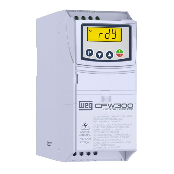
4 ABOUT THE CFW300
The CFW300 frequency inverter is a high-performance product which allows speed and torque control of
three-phase induction motors. This product provides the user with the options of vector (V V W ) or scalar
(V/f) control, both programmable according to the application.
5 TERMINOLOGY
English
Table 1: Terminology of the CFW300 inverters
Model Identification
Product
Degree of
Frame
Rated
Phase
Rated
Brake
and Series
Protection
Size
Current
Number
Voltage
Ex.:
CFW300
A
01P6
S
2
NB
Refer to Table 2
NB = without braking reostática
CFW300
DB = with braking reostática
20 = IP20
Table 2: Available options for each field of the nomenclature according to the rated current and voltage of the inverter
13259186
Output Rated
Frame Size
N° of Phases
Current
01P6 = 1.6 A
02P6 = 2.6 A
04P2 = 4.2 A
06P0 = 6.0 A
01P6 = 1.6 A
S = single-phase power supply
02P6 = 2.6 A
04P2 = 4.2 A
06P0 = 6.0 A
07P3 = 7.3 A
A
01P6 = 1.6 A
02P6 = 2.6 A
04P2 = 4.2 A
T = three-phase power supply
06P0 = 6.0 A
07P3 = 7.3 A
01P6 = 1.6 A
02P6 = 2.6 A
04P2 = 4.2 A
D = DC power supply
06P0 = 6.0 A
07P3 = 7.3 A
10P0 = 10.0 A
B = single-phase or three-phase power supply or DC 2 = 200...240 Vac
B
15P2 = 15.2A
T = three-phase power supply or DC
6 RECEIVING AND STORAGE
The CFW300 is supplied packed in a cardboard box. There is an identification label affixed to the outside
of the package, identical to the one affixed to the side of the inverter.
Verify whether:
The CFW300 identification label corresponds to the purchased model.
„
Any damage occurred during transportation.
„
Report any damage immediately to the carrier.
If the CFW300 is not installed soon, store it in a clean and dry location (temperature between -25 ºC and
60 ºC (-13 ºF and 140 ºF)), with a cover to prevent dust accumulation inside it.
7 IDENTIFICATION LABEL
Model (Inverter
Manufacturing date (14 corresponds
intelligent code)
Serial number
to the week and I to the year)
Production order
WEG stock item
Rated output data
Rated input data
(voltage, current and
(voltage, current and frequency)
frequency)
Figure 1: Description of the CFW300 identification label
8 DIMENSIONS
View of the mounting base
Front view
A
L
A
B
H
L
P
Frame
Size
mm
mm
mm
mm
mm
(in)
(in)
(in)
(in)
(in)
A
35.0 (1.37)
50.1 (1.97)
157.9 (6.22)
70.0 (2.76) 148.4 (5,84) 0.900 (1.98)
B
35.0 (1.37)
50.1 (1.97) 198.9 (8.08) 70.0 (2.76) 158.4 (6.24) 1.340 (2.98)
Dimension tolerance: ±1,0 mm (±0,039 in)
Figure 2: Inverter dimensions for mechanical installation
9 INSTALLATION AND CONNECTION
Environmental Conditions
Avoid:
Direct exposure to sunlight, rain, high humidity or sea-air.
„
Inflammable or corrosive gases or liquids.
„
„
Excessive vibration.
Dust, metallic particles or oil mist.
„
Environment conditions permitted for the operation of the inverter:
„
Temperature surrounding the inverter: 0 ºC to 50 ºC ( 32 ºF to 122 ºF) – IP20.
For temperatures surrounding the inverter higher than the specifications above, it is necessary to apply
„
of 2 % of current derating for each degree Celsius, limited to an increase of 10 ºC (50 ºF).
Air relative humidity: 5 % to 95 % non-condensing.
„
„
Maximum altitude: up to 1000 m (3.300 ft) - rated conditions.
From 1000 m to 4000 m (3.300 ft to 13.200 ft) – 1 % of current derating for each 100 m above 1000 m
„
of altitude.
„
Pollution degree: 2 (according to EN50178 and UL508C), with non-conductive pollution. Condensation
must not originate conduction through the accumulated residues.
10 ELECTRICAL INSTALLATION
Hardware
Software
Version
Version
20
---
---
DANGER!
Blank = standard
„
The following information is merely a guide for proper installation. Comply with applicable
Sx = special software
local regulations for electrical installations.
Blank = standard
„
Make sure the AC power supply is disconnected before starting the installation.
Hx = special hardware
„
The CFW300 must not be used as an emergency stop device. Provide other devices
for that purpose.
Rated Voltage Brake
1 - power terminals
1
2 - grounding points
2
3 - connector of the
1 = 110...127 Vac
4 - control terminals
3
5 - connector of the I/O
4
5
2 = 200...240 Vac
NB
1
2
Figure 3: Power terminals, grounding points and recommended tightening torque
10.1 POWER CONNECTIONS
3 = 280...340 Vdc
Description of the power terminals:
L/L1, N/L2, L3 (R,S,T): power supply connection.
U, V and W: connection for the motor.
DB
-UD: negative pole of the DC power supply.
or 280...340 Vdc
+UD: positive pole of the DC power supply.
+BR, BR: connection of the braking resistor (available for frame size B models).
PE: grounding connection.
PE
Power
Fuses
supply
Negative pole of the DC power supply (-UD)
Positive pole of the DC power supply (+UD)
Disconnecting
PE -UD +UD
switch
W
V
U
PE
PE
U
V
W
Shielding
Only available for the specific models of frame size A (see table 2).
(a) Frame size A DC power supply
PE
Power
Fuses
supply
Negative pole of the DC power supply (-UD)
Positive pole of the DC power supply (+UD)
Disconnecting
PE
L1
L2
L3
-UD
+
UD
switch
Side view
P
W
V
U
PE
PE
U
V
W
+BR
BR
Shielding
(c) Frame size B DC power supply
Figure 4: (a) to (d) Power and grounding connections
Recommended
10.2 INSTALLATIONS ACCORDING TO EUROPEAN DIRECTIVE OF ELECTROMAGNETIC
Weight
Torque
Mounting
COMPATIBILITY
Bolt
kg
N.m (Ibf.in)
(lb)
The CFW300 inverter series, when properly installed, meet the requirements of the directive of the
M4
2 (17.7)
electromagnetic compatibility.
M4
2 (17.7)
These inverters were developed for professional applications only. Therefore, the emission limits of
harmonic currents by the standards EN 61000-3-2 and EN 61000-3-2/A 14.
10.2.1 Conformal Installation
1. Shielded output cables (motor cables) with shield connected at both ends, motor and inverter, by meanse
of a low impedance to high frequency connection. Maximum motor cable length and conduced and
radiated emission levels according to Table 6.
2. Shielded control cables, keeping the separation distance from other cables according to Table 3.2 the
user's manual.
3. Grounding of the inverter according to instruction of the 3.2.4 Grounding Connections the user's manual.
4. Grounded power supply.
5. Use short wiring to ground the external filter or inverter.
6. Ground the mounting plate using a flexible braid as short as possible. Flat conductors have lower
impedance at high frequencies.
7. Use sleeves for cable conduits whenever possible.
The CFW300 is suitable for application in a circuit able to supply not more than 30.000 symetric Arms
maximum of 127 / 240 V, when protected by fuses classified as indicated below:
Power Wire Size for
DC+ and BR Terminals
Braking rms Current
Recommended
Resistor
Maximum Current
Grounding Wire Size
Power Wire Size
Recommended Fuse WEG
communication accessory
Current
I²t [A²s]
expansion accessory
Recommended Torque
Frame
Grounding
Power
Circuit Breaker
Size
Points
Terminal
N.m
Lbf.in
N.m
Lbf.in
A and B
0.8
7.2
0.8
7.2
Maximum Motor
Overload Currents
Output Rated Current
Frame Size
Power Supply Rated Voltage
Number of Input Phases
PE
Power
Fuses
supply
L1/L
L2/N
L3*
PE L1 L2 L3
Disconnecting
Inverter
switch
DANGER!
The inverter must be connected to a protective ground (PE).
Use a minimum wire gauge for ground connection equal to the indicated in Table 3.
Connect the inverter grounding connections to a ground bus bar, to a single ground point
or to a common grounding point (impedance ≤ 10 Ω).
W
V
U
PE
PE
U
V
W
The neuter conductor of the line that feeds the inverter must be solidly grounded; however
this conductor must not be used to ground the inverter.
Shielding
Do not share the grounding wiring with other equipment that operate with high currents
(e.g.: high voltage motors, welding machines, etc.).
(*) The power terminal L3 is not available in models of frame size
A single-phase
NOTE!
(b) Frame size A single-phase and three-phase power supply
The wire gauges listed in Table 3 are guiding values. Installation conditions and the maximum
PE
permitted voltage drop must be considered for the proper wiring sizing.
Power
Fuses
supply
L1/L
L2/N
L3
10.3 CONTROL CONNECTIONS
PE
L1
L2
L3
-UD
UD
Disconnecting
+
switch
1
2
3
4
(a) NPN Configuration
1
2
3
4
W
V
U
PE
PE
U
V
W
+BR
BR
Shielding
24 V
Only available for the 10-A model (see table 2).
External supply
(d) Frame size B single-phase and three-phase power supply
(b) PNP Configuration
For the correct connection of the control, use:
1. Gauge of the cables: 0.5 mm² (20 AWG) to 1.5 mm² (14 AWG).
2. Maximum torque: 0.5 N.m (4.50 lbf.in).
3. Wiring of the connector of the control board with shielded cable and separated from the other wiring
(power, command in 110 V / 220 Vac, etc.).
10.3.1 Emission and Immunity Levels
EMC Phenomenon
Emission:
Mains terminal disturbance voltage
Frequency range: 150 kHz to 30 MHz)
Electromagnetic radiation disturbance
Frequency Range: 30 MHz to 1000 MHz)
Immunity:
Electrostatic discharge (ESD)
Fast transient-Burst
Conducted Radio-Frequency
Common Mode
Surges
Radio-Frequency Electromagnetic
Field
Table 3: List of models of CFW300 series, main electrical specifications
mm²
(AWG)
[A]
[Ω]
(Imax)
[A]
mm²
(AWG)
mm²
(AWG)
[A]
WEG
[A]
[HP/kW]
1 min
[Arms]
[Arms]
5
6
7
8
9
10
11
12
Connector
Description
(*)
1
DI1
Digital input 1
2
DI2
Digital input 2
3
DI3
Digital input 3
4
DI4
Digital input 4
5
GND
Reference 0 V
(+) AI1 (-)
6
AI1
Analog input 1 (Current)
(0 to 20) mA
AI1
7
GND
Reference 0 V
(4 to 20) mA
(0 to 10) V
8
AI1
Analog input 1 (Tension)
9
+10 V
Reference +10 Vdc for potentiometer
5
6
7
8
9
10
11
12
10
DO1-RL-NC
Digital output 1 (NC contact of relay 1)
11
DO1-RL-C
Digital output 1 (Common point of relay 1)
12
DO1-RL-NO
Digital output 1 (NO contact of relay 1)
(*) For further information, refer to the detailed specification in table 7.
- The CFW300 inverters are supplied with the digital inputs configured
as active low (NPN). In order to change the configuration, check the
use of parameter P271 in the programming manual of the CFW300.
(+) AI1 (-)
- Analog input AI1 is set for input 0 to 10 V; in order to change it, check
(0 to 20) mA
AI1
parameter P233 of the programming manual of the CFW300.
(4 to 20) mA
(0 to 10) V
Figure 5: (a) and (b) Signals of C300 control card connector
Table 4: Emission and immunity levels
Basic Standard
Level
It depends on the inverter model on the length of the
IEC/EN 61800-3
cabo motor cable. Refer to Table 6
IEC 61000-4-2
4 kV for contact discharge and 8 kV for air discharge
2 kV / 5 kHz (coupling capacitor) input cables
IEC 61000-4-4
1 kV / 5 kHz control cables and remote HMI cables
2 kV / 5 kHz (coupling capacitor) motor cables
0.15 to 80 MHz; 10 V; 80 % AM (1 kHz)
IEC 61000-4-6
Motor, control and remote HMI cables
1.2/50 μs, 8/20 μs
IEC 61000-4-5
1 kV line-to-line coupling
2 kV line-to-ground coupling
80 to 1000 MHz
IEC 61000-4-3
10 V/m
80 % AM (1 kHz)
Advertisement

Subscribe to Our Youtube Channel
Related Manuals for WEG CFW300


Summary of Contents for WEG CFW300
- Page 1 If the CFW300 is not installed soon, store it in a clean and dry location (temperature between -25 ºC and 60 ºC (-13 ºF and 140 ºF)), with a cover to prevent dust accumulation inside it.
-
Page 2: Faults And Alarms
32 = 2 Ramp Multispeed 4 = Forward 33 = 2 Ramp E.P. Ac. CFW300 inverters are installed with external filter when it is intended to reduce the disturbance conducted 15 CONSIDERED STANDARDS 5 = Reverse 34 = 2 Ramp E.P. De.
Need help?
Do you have a question about the CFW300 and is the answer not in the manual?
Questions and answers