Table of Contents
Advertisement
Advertisement
Table of Contents

Related Manuals for Inovance AM500 Series


Summary of Contents for Inovance AM500 Series
- Page 1 *PS00008837A00*...
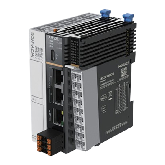
- Page 3 Preface ■ Introduction The AM500 is a new generation of medium‑sized PLC which supports EtherCAT bus control and dual‑port network switching function, FB/FC‑based technology encapsulation and reuse, and multi‑level network communication through RS485, Ethernet and EtherCAT interfaces. It support 16 expansion modules. RS485/RS232/DI/ DO/AI/AO/RTC clock/TF card functions can be provided through the expansion cards.
-
Page 4: Revision History
■ Access to the Guide This guide is not delivered with the product. You can obtain the PDF version in the following way: http://www.inovance.com Visit , go to Support > Download, search by keyword, ● and then download the PDF file. -
Page 5: Warranty
Damage or secondary damage caused by force majeure (natural disaster, ● earthquake, and lightning strike) The maintenance fee is charged according to the latest Price List of Inovance. If otherwise agreed upon, the terms and conditions in the agreement shall prevail. For details, see the Product Warranty Card. -
Page 6: General Safety Instructions
Use this equipment according to the designated environment requirements. ● Damage caused by improper use is not covered by warranty. Inovance shall take no responsibility for any personal injuries or property damage ● caused by improper use. ■ Safety Levels and Definitions Indicates that failure to comply with the notice will result in death or severe personal injuries. - Page 7 Unpacking Do not install the equipment if you find damage, rust, or signs of use on the equipment ● or accessories upon unpacking. Do not install the equipment if you find water seepage or missing or damaged ● components upon unpacking. Do not install the equipment if you find the packing list does not conform to the ●...
- Page 8 Handle the equipment with care during transportation and mind your steps to prevent ● personal injuries or equipment damage. When carrying the equipment with bare hands, hold the equipment casing firmly with ● care to prevent parts from falling. Failure to comply may result in personal injuries. Store and transport the equipment based on the storage and transportation ●...
- Page 9 Read through the guide and safety instructions before installation. ● Do not install this equipment in places with strong electric or magnetic fields. ● Before installation, check that the mechanical strength of the installation site can bear ● the weight of the equipment. Failure to comply will result in mechanical hazards. Do not wear loose clothes or accessories during installation.
- Page 10 Equipment installation, wiring, maintenance, inspection, or parts replacement must be ● performed only by professionals. Before wiring, cut off all the power supplies of the equipment, and wait for at least the ● time designated on the equipment warning label before further operations because residual voltage still exists after power‑off.
- Page 11 Follow the proper electrostatic discharge (ESD) procedure and wear an anti‑static wrist ● strap to perform wiring. Failure to comply may result in damage to the equipment or to the internal circuit of the product. Use shielded twisted pairs for the control circuit. Connect the shield to the grounding ●...
- Page 12 Do not touch the equipment casing, fan, or resistor with bare hands to feel the ● temperature. Failure to comply may result in personal injuries. Prevent metal or other objects from falling into the equipment during operation. Failure ● to comply may result in a fire or equipment damage. Maintenance Equipment installation, wiring, maintenance, inspection, or parts replacement must be ●...
-
Page 13: Safety Label
Submit the repair request according to the warranty agreement. ● When the fuse is blown or the circuit breaker or earth leakage current breaker (ELCB) ● trips, wait for at least the time designated on the equipment warning label before power‑ on or further operations. -
Page 14: Product Information
1 Product Information Description of the Model and Nameplate ■ Description of the Model Series 3 Inputs/Outputs ① AM: AM series programmable logic 08: 8 inputs controller 08: 8 outputs Model code ④ Output type ② 5: EtherCAT TN: Sink transistor 2: 2 x Ethernet X: Number of EtherCAT axes, 1 indicating 8 axes, 2 indicating 16 axes... - Page 15 Model Description Code AM521‑0808TN AM500 Series 8‑input 8‑output PLC (8 01440477 axes) AM522‑0808TN AM500 Series 8‑input 8‑output PLC (16 01440475 axes) Components ‑ ‑...
- Page 16 Terminal Sign Description Indicator Description Type Color ON: Input/Output ① ● active Yellow I/O status indicator IN/OUT display green OFF: Input/Output ● inactive ON: The power ● supply is normal. Yellow Power OFF: The power green ● supply is abnormal. ON: The user ●...
- Page 17 Terminal Sign Description Indicator Description Type Color Enables Type‑C ④ communication ‑ ‑ interface with PC. Expansion 01/02 Receives ‑ Expansion card ⑤/‑ ⑥ card slot expansion card options are available " Appendix: for extended functions. Expansion Card Options " on page 43 485+ ‑...
-
Page 18: Product Specifications
Product Specifications 1.3.1 General Specifications Item Specification Program 10 MB capacity Data capacity 20 MB, of which 512 KB is retentive at power failure AM521: 8 axes EtherCAT ● AM522: 16 axes ● Axis control 4‑axis synchronization within 1ms cycle (time calculated performance based on motion control) Electronic... - Page 19 Item Specification Supports up to 127 EtherCAT slaves, with a minimum EtherCAT ● synchronization cycle of 1ms Supports disabling and scanning of slaves ● Two Ethernet ports share one IP address, network switching function supported Supports Ethernet/IP master/slave: 16 slaves supported when used as a master;...
-
Page 20: Power Supply Specifications
Item Specification High‑speed 8‑channel hardware inputs Maximum input frequency: 200 kHz Pulse input Supports up to 4 encoder axes Supports A/B phase, pulse/direction, CW/CCW, single‑phase pulse signal 8‑channel hardware outputs Output frequency: 5 Hz to 200 kHz Supports up to 4 pulse axes, which share motion control Pulse output instructions with the bus axis Supports A/B phase, pulse/direction, CW/CCW, single‑phase... -
Page 21: Input Specifications
Item Specification Rated bus output voltage 5 VDC (4.75 VDC to 5.25 VDC) Rated bus output current 2A (max@5 V) 24 V input power supply protection Protection against short circuit and reverse connection Hot swap Not supported 1.3.3 Input Specifications Item Specification Input type... - Page 22 Item Specification Output voltage class 24 VDC±10% (21.6 VDC to 26.4 VDC) Output load 0.5 A/point; 2 A/8 points (resistive load) Output load 7.2 W/point; 24 W/8 points (inductive load) Output load 5 W/point; 18 W/8 points (lamp load) High‑speed output ON/OFF <...
- Page 23 ‑ ‑...
-
Page 24: Mechanical Installation
2 Mechanical Installation Installation Environment Take the operability, serviceability, and adaptability to environment into account when installing the PLC. Item Specification Operating No corrosive and flammable gas and no excessive conductive dust environment Altitude ≤2000 m (80 kPa) Pollution 2 or less degree Immunity 2 kV on power supply line (Conforms to IEC 61000‑4‑4) - Page 25 Item Specification Operating humidity: ‑20°C to +55°C (when installed horizontally), ‑20°C Operating ● to +45°C (when installed non‑horizontally) humidity Relative humidity: <95% RH, non‑condensing ● Note: Install a fan or air conditioner in the direction of the ventilation holes when the operating temperature is greater than the maximum allowable temperature.
- Page 26 Item Specification Installation The PLC can be installed in four directions, as shown in " 2.2 Installation position and Requirements " on page 25 limit Limit: When installed horizontally: ● ■ Input derating: The PLC can operate with full load at ambient temperature of 45°C.
-
Page 27: Installation Requirements
Installation Requirements The PLC can be mounted horizontally or vertically, on top or at the bottom of the electric cabinet. Different mounting options require different operating temperatures, " 2.1 Installation Environment " on page 22 ■ Optimal mounting option The PLC is most preferably installed horizontally. The heat dissipation is realized by natural convection mode. -
Page 28: Other Mounting Options
If there is a high‑temperature heat source (heater, transformer, large resistor, etc.) in vicinity of the product, keep the product away from the heat source by at least 100 ■ Other mounting options Other mounting options require the same clearance as the optimal mounting option and are shown in the following figure. -
Page 29: Installation Precautions
In case of vertical installation: PLC must be installed below all I/O modules. ● Hold the cables with a cable duct to prevent the weight of cables being ● applied to the lower end plate, which may result loose of the PLC from the DIN rail. -
Page 30: Installation Method
Installation Method The PLC is mounted onto a DIN rail in conformity with IEC 60715 (width: 35 mm, thickness: 1 mm). The dimensions (unit: mm) are shown below. When installed on a DIN rail other than the recommended one (especially the one whose thickness is not 1.0 mm), the product will not fit in place as the mounting hook does not work. - Page 31 If the mounting hook is pressed down, it is locked. ● If the mounting hook is lifted up, it is unlocked. ● Press down the mounting hook to lock the PLC to the DIN rail. When the PLC is not installed on the rail, keep the mounting hook in the locked state. Keeping the mounting hook unlocked for a prolonged time may cause the hook to fail.
- Page 32 the top of it to the top of the DIN rail, and then tighten the screw to lock the end plate in place, as shown below. ■ Removing the PLC Pry the DIN rail mounting hook upwards with a tool such as slotted screwdriver, hold the protrusions and pull the PLC out straight forward, and then press down the top of the DIN rail mounting hook.
- Page 33 ‑ ‑...
-
Page 34: Terminal Layout
3 Electrical Installation Terminal Layout Right Right Signal Left Signal Left Termi‑ Terminal X0 input Y0 output X1 input Y1 output X2 input Y2 output X3 input Y3 output X4 input Y4 output X5 input Y5 output X6 input Y6 output X7 input Y7 output Input common terminal... - Page 35 The length of a high‑speed I/O interface extension cable must be within 3.0 ● To prevent interference, route the I/O interface extension cable and the ● power cable (high‑voltage/high‑current cables) through different non‑ parallel routes. Wiring of Input Terminals ■ Wiring of sink input ‑...
-
Page 36: Output Terminal Wiring
■ Wiring of source input Output terminal wiring Note Connect a flywheel diode when connecting the external inductive load. Diodes can be 1N4001 or similar. ‑ ‑... -
Page 37: Communication Wiring
4 Communication Wiring Communication Networking This PLC can be connected to other sites, ERP, MES and other systems through Ethernet interface, or connected to other slaves (such as MD520, MD800, SV660N and SV680N drives) or other modules with EtherCAT function through EtherCAT interface. With GE20 series extension cards, this PLC can also be connected to H5U, SV630C, and IR311 series industrial robots through RS485 or RS232 communication, as shown below. -
Page 38: Cable Connection
Material Applicable Cross Sectional Suzhou Yuanli Name Area of the Cable Model Crimping Model Crimping Tool Tool Tubular E0308 KST2000L 0308 YAC‑5 E0508 0508 0.75 E7508 7508 E1008 1008 E1508 1508 If you use other types of tubular lug, crimp the lug to the cables according to the shape and dimension requirements shown in the figure below. -
Page 39: Ethernet Communication
Description Left Terminal Right Terminal Description 485+ +24V 24 VDC (+) RS485 differential pair (+) RS485 differential 485‑ 24 VDC (‑) pair (‑) RS485 ground Wiring ● Select tubular cables referring to " 4.2 Cable Selection " on page 35 and insert the cables into the communication ports. - Page 40 Item Description Number of slaves Up to 127 EtherCAT frame length 44 to 1,498 bytes Process data A maximum of 1486 bytes per Ethernet frame ■ Wiring The PLC provides a CN3 port for EtherCAT bus communication. The communication cable must meet the following requirements: Communication cable requirements Signal pin assignment Signal...
- Page 41 The cable between devices cannot exceed 100 m when the EtherCAT bus is used, exceeding of which may attenuate the signal and affect normal communication. Technical requirements 100% continuity test, without occurrence of short circuit, open circuit, misalignment, or poor contact. Cables meeting the following requirements are recommended. Item Specification Cable type...
- Page 42 To avoid interference, do not bundle the cable together with an AC power cable or high voltage cable. ‑ ‑...
-
Page 43: Operation And Maintenance
If the ERR indicator flashes slowly, it indicates the burning fails. Check that the PLC model configured in the program file is consistent with the actual PLC model. If the problem persists, contact Inovance for technical support. 5. Power off and on the PLC again. - Page 44 Install the TF extension card with power off. 2. Power on the PLC again. If the RUN and ERR indicators flash quickly, it indicates that the firmware upgrade is in progress. If the RUN and ERR indicators are OFF, it indicates that the firmware is successfully upgraded.
- Page 45 Appendix: Expansion Card Options Model Category Description Slot GE20‑4DI Digital input and 4‑channel input output 24 VDC input Sink/Source GE20‑4DO‑TN 4‑channel transistor sink output 24 VDC output GE20‑2AD1DA‑I AI and AO 2‑channel analog input and 1‑channel analog output (current type) GE20‑2AD1DA‑V 2‑channel analog input and 1‑channel analog output...
Need help?
Do you have a question about the AM500 Series and is the answer not in the manual?
Questions and answers