Table of Contents
Advertisement
Advertisement
Table of Contents

Related Manuals for Inovance Easy521


Summary of Contents for Inovance Easy521
- Page 1 *PS00005506A02*...
-
Page 3: Standards Compliance
Preface ■ Introduction The Easy521/Easy522/Easy523 series PLC, the new generation of small PLC developed by Inovance, supports network switchover through two network ports and allows process packaging and reuse through FB/FC function. With RS485, Ethernet, and EtherCAT, a multi‑layer network communication can be realized through this PLC, with 16 modules extendable. -
Page 4: Revision History
■ Warranty Inovance provides an 18‑month warranty to the equipment from the date of shipment (subject to the barcode on the product) for failure or damage that occurs during normal use. If otherwise agreed upon, the agreed terms and conditions shall prevail. - Page 5 Force majeure (such as natural disaster, earthquake, and lightning strike) and the ● secondary damage caused thereof The maintenance fee is charged according to the latest Maintenance Price List of Inovance. If otherwise agreed upon, the agreed terms and conditions shall prevail. For details, see Product Warranty Card. ‑ ‑...
-
Page 6: Fundamental Safety Instructions
Use this product in environments meeting the design and specification ● requirements; otherwise, a fault may occur. Noncompliance‑caused malfunction or damage to parts are not covered in product quality warranty. Inovance shall take no responsibility for any personal injuries or property damage ● caused by improper usage. ■... - Page 7 Unpacking Do not install the equipment if you find any sign of damage, rust, or prior use on the ● equipment or accessories. Do not install the equipment if you find any sign of water seepage or missing or damaged ●...
- Page 8 Installation Installation must be carried out by the specialists who have received the necessary ● electrical training and understood enough electrical knowledge. Ensure no unprofessional person has access to the equipment. Read through the guide and safety instructions before installation. ●...
- Page 9 During installation, use a piece of cloth or paper to cover the top of the product to ● prevent metal chippings, oil, and water from entering into the product when drilling holes. Failure to comply will cause product malfunctions. After installation, remove the cloth or paper for effective ventilation and cooling.
- Page 10 Do not connect the input power supply to the output end of the equipment. Failure to ● comply can result in equipment damage or even a fire. When connecting a drive to the motor, make sure the phase sequence of the drive and ●...
- Page 11 Perform a trial run after wiring and parameter setting to ensure that the equipment ● operates safely. Failure to comply may result in personal injuries or equipment damage. Before power‑on, ensure that the nominal voltage of the equipment is consistent with ●...
- Page 12 Perform routine and periodic inspection and maintenance on the equipment according ● to maintenance requirements and keep a maintenance record. Repair Only professionals are allowed to perform installation, wiring, maintenance, inspection ● or parts replacement on the equipment. Do not repair the equipment after power‑on. Failure to comply can result in the risk of ●...
-
Page 13: Safety Labels
■ Safety labels To ensure safe operations, comply with safety signs on the device, and do not damage or remove the safety labels. See the following table for descriptions of the safety labels. Safety Label Description Read through the safety instructions before operating the equipment. ●... -
Page 14: Product Information
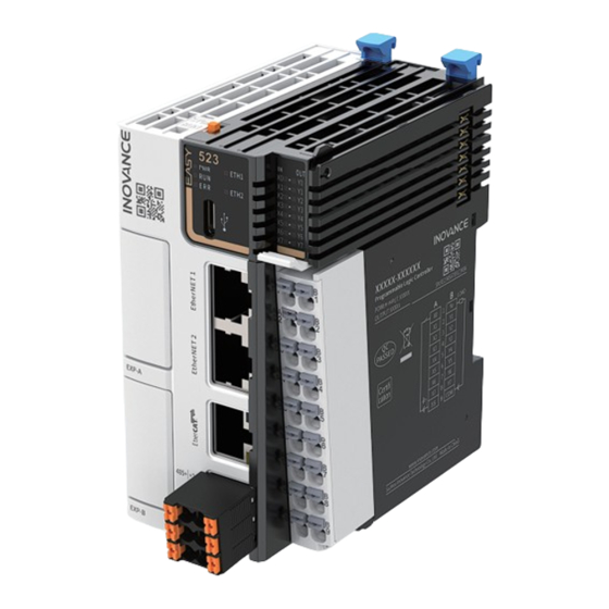
1 Product Information Model and Nameplate ■ Model Product series ③ Inputs/Outputs ① Easy: Easy series programmable logic 08: 8 inputs controller 08: 8 outputs Series No. ④ Output type ② X stands for 1, 2, 3, i.e. 521, 522, 523 TN: SINK transistor 5: With EtherCAT 2: Two Ethernet interfaces... - Page 15 Model Description Code Easy521‑0808TN Easy500 series 8‑axis programmable 01440385 controller with 8 inputs and 8 outputs Easy522‑0808TN Easy500 series 16‑axis programmable 01440383 controller with 8 inputs and 8 outputs Easy523‑0808TN Easy500 series 32‑axis programmable 01440326 controller with 8 inputs and 8 outputs Components ‑...
- Page 16 Terminal Terminal code Assignment Indicator Description type color Solid ON: Indicates ① ● the input or output indicator is active. I/O status Yellow‑ IN/OUT display green OFF: Indicates the ● input or output is inactive. ‑ ‑...
- Page 17 Terminal Terminal code Assignment Indicator Description type color Solid ON: Indicates ● that the power supply is normal. Yellow‑ Power supply green OFF: Indicates that ● the power supply is abnormal. Solid ON: Indicates ● that the user program is running. Yellow‑...
- Page 18 Terminal Terminal code Assignment Indicator Description type color RUN/STOP Used to control ③ DIP switch the operation of ‑ ‑ the master. Used for Type‑C ④ communication ‑ ‑ interface with PC. Extension 01/02 Used for ‑ For details of ⑤/‑...
-
Page 19: Product Specifications
Product Specifications 1.3.1 General Specifications Item Easy521‑0808TN Easy522‑0808TN Easy523‑0808TN Program data 200 k‑step user program capacity 2 Mb user‑defined variables, in which 128 kb variables are retentive at power failure; About 150 k soft elements (Elements after No. 1000 are retentive at power failure.) -
Page 20: Power Supply Specifications
Item Easy521‑0808TN Easy522‑0808TN Easy523‑0808TN Type‑C Supports user program download/upload and firmware upgrade through GE20–TF extension card. IP rating IP20 53 mm x 100 mm x 80 mm Dimensions (W x H x Weight About 197 g 1.3.2 Power Supply Specifications... -
Page 21: Output Specifications
Item Specifications Low‑speed: 2 ms to 1000 ms ● Software filter time High speed: 2 μs to 1000 μs ● Isolation mode Isolated by digital isolator chip Common terminal mode 8‑point/common terminal (The polarity +/‑ of input power supply is changeable.) Input action display The input indicator lights up (controlled by software) when the input is in drive state. - Page 22 Item Specifications Short circuit protection Providing protection against short circuit of each circuit (The short circuit protection state can be cancelled through a power cycle.) External inductive load Connect a flywheel diode when connecting the external protection inductive load. Output action display The output indicator lights up (controlled by software) when the output is in drive state.
-
Page 23: Mechanical Installation
2 Mechanical Installation Installation Environment Take the operability, serviceability, and adaptability to environment into account when installing the PLC. Item Specification Working Free from corrosive gas and flammable gas, as well as excessive environment conductive dust Altitude Up to 2000 m ( 80 kPa) Pollution degree Immunity... - Page 24 Item Specification Operating temperature: ‑20 °C to +55 °C (horizontally), ‑20 °C to +45 °C Operating ● (non‑horizontally) temperature/ Relative humidity: < 95% RH (without condensation) humidity ● Note: Install a fan or air conditioner in the direction of the cooling hole when the operating temperature is greater than the maximum temperature.
- Page 25 Item Specification Installation Installation position: The PLC can be installed in four directions as shown position and " 2.2 Installation Position " on page 24 limit Limit: When installed horizontally: ● ■ Input derating: The PLC can operate with full load at ambient temperature of 45℃.
-
Page 26: Installation Position
Installation Position This product can be installed in four positions (namely four installation directions): Horizontally, vertically, and top or bottom of the cabinet. It is recommended to install the PLC horizontally. Different installation positions require different operating temperatures and limits. For details, see "... -
Page 27: Other Installation Positions
■ Other installation positions The surrounding clearance required on other installation positions are the same as the optimal one. Other installation positions are shown in the diagram below. In case of vertical installation: Install the PLC below all I/O modules. ●... -
Page 28: Installation Dimensions
Do not connect/disconnect the module with power ON. This may lead to master restart or user data loss or damage. Prevent the master, module enclosure, or terminals from dropping or suffering ● from impact or shock. Installation Dimensions The installation dimensions (in mm) are shown in the figure below. Installation Methods The module is mounted onto a DIN rail that complies with IEC 60715 (width: 35 mm, thickness: 1 mm). -
Page 29: Installing The Master
When installed on a DIN rail other than the recommended one (especially the one whose thickness is not 1.0 mm), the module will not fit in place as the mounting hook does not work. ■ Installing the master 1. Align the module with the DIN rail and push the module in the direction indicated by the arrow until you hear a clicking sound, as shown below. - Page 30 Keep the mounting hook locked when the controller is not mounted on the rail. If the mounting hook is kept unlocked for an extended period of time, it may malfunction. ■ Installing the module to the master Install the extension module to the master through top and bottom rails, as shown below.
-
Page 31: Removing The Module
■ Removing the module Pry the mounting hook upwards with a tool such as a straight screwdriver or similar, and pull out the module forwardly. Then press down the top of the mounting hook. ‑ ‑... -
Page 32: Electrical Installation
3 Electrical Installation Layout of Terminals Terminals on the Signals on the right Signals on the left Terminals on the left right X0 input Y0 output X1 input Y1 output X2 input Y2 output X3 input Y3 output X4 input Y4 output X5 input Y5 output... - Page 33 The length of a high‑speed I/O interface extension cable must be within 3.0 ● To prevent interference, route the I/O interface extension cable and the ● power cable (high‑voltage/high‑current cables) through different non‑ parallel routes. Wiring of Input Terminals ■ SINK input wiring ‑...
- Page 34 ■ SOURCE input wiring Wiring of Output Terminals Note Connect a flywheel diode when connecting the external inductive load. Diodes can be 1N4001 or similar. ‑ ‑...
-
Page 35: Communication Connection
4 Communication Connection Networking This PLC can be connected to other sites, ERP, MES and other systems through Ethernet interface, or connected to other slaves (such as MD520, MD800, SV630N and SV660N drives) or other modules with EtherCAT function through EtherCAT interface. With GE20 series extension cards, this PLC can also be connected to H5U, SV630C, and IR311 series industrial robots through RS485, RS232, or CAN communication, as shown below. -
Page 36: Cable Connection
Material Applicable cross sectional Suzhou Yuanli name area GB/mm Model Crimping Model Crimping tool tool E0308 0308 E0508 0508 Tubular 0.75 E7508 KST2000L 7508 YAC‑5 E1008 1008 E1508 1508 If you use other types of tubular lug, crimp the lug to the twisted pair as shown below. Cable Connection ■... -
Page 37: Ethernet Communication
Description Terminals on the left Terminals on the Description right RS485 differential 485+ +24V 24 VDC power supply pair (+) RS485 differential 485‑ 24 VDC power supply (‑) pair (‑) Communication grounding terminal of RS485 Communication specifications ● Item Description Number of channels supported Three channels at most (one built‑in and two extended in the extension card,... - Page 38 Disconection: Pull out the connector by pressing the tail of the registered jack. ● EtherCAT Communication Description ■ EtherCAT Specifications Item Description Communication protocol EtherCAT Protocol Available services CoE (PDO, SDO) Synchronization mode Distributed clock for the drive and synchronous input/output for I/O Physical layer 100BASE‑TX...
- Page 39 Signal pin assignment Signal Signal direction Description Output Data transmission+ TD‑ Output Data transmission‑ Input Receive data (+) ‑ ‑ Not used ‑ ‑ Not used RD‑ Input Receive data (‑) ‑ ‑ Not used ‑ ‑ Not used Length requirement The cable between devices cannot exceed 100 m when the EtherCAT bus is used, exceeding of which may attenuate the signal and affect normal communication.
- Page 40 Item Specification Cross sectional area 26AWG of the cable Cable category Twisted pair Number of pairs RS485 Communication Instructions It is recommended to use a shielded twisted pair cable as the RS485 bus. Connect a 120 Ω termination resistor to both ends of the bus respectively to prevent signal reflection.
-
Page 41: Operation And Maintenance
PLC. If the model and password are both correct but the programming failure still occurs, contact Inovance for technical support. - Page 42 SD Card Firmware Upgrade 1. Load the SD card (maximum capacity 32 GB, file format FAT32) to the TF extension card and the PLC. Install the TF extension card with power off. 2. Power on the PLC again. The RUN and ERR indicators flash quickly for 3s, indicating that the firmware upgrade begins.
- Page 43 Appendix: Extension Card Options Model Type Description Slot GE20‑4DI Digital input/ 4 inputs output 24 VDC input Source/Sink GE20‑4DO‑TN 4 transistor sink outputs 24 VDC output GE20‑ Analog input/ 2 analog inputs and 1 analog 2AD1DA‑I output output (current type) GE20‑...
Need help?
Do you have a question about the Easy521 and is the answer not in the manual?
Questions and answers