Table of Contents
Advertisement
Advertisement
Table of Contents

Related Manuals for Neoway M590


Summary of Contents for Neoway M590
- Page 1 M590 GPRS Module Hardware User Guide Version 1.2...
- Page 2 Neoway provides customers complete technical support. If you have any question, please contact your account manager or email to the following email addresses: Sales@neoway.com.cn...
- Page 3 M590 GPRS Module Hardware User Guide Revision Record Issue Changes Revised By Date V1.0 Initial draft Qiao Naiwei 2013-10 V1.1 Modified the description of VCCIO Qiao Naiwei 2014-04 V1.2 Added chapter 4. Weng Peibin 2014-05 Copyright © Neoway Technology Co., Ltd...
-
Page 4: Table Of Contents
M590 GPRS Module Hardware User Guide Contents About This Document ......................1 1 Introduction to M590 ......................1 1.1 Overview ............................. 1 1.2 Block Diagram ..........................1 1.3 Specifications ..........................2 2 Pin Description and PCB Foot Print ................3 2.1 Specifications and Encapsulation .................... - Page 5 Table of Figures Figure 2-1 Top view of the M590 module ....................3 Figure 2-2 PCB foot print recommended for M590 (unit: mm) .............. 6 Figure 3-1 Current peaks and voltage drops .................... 7 Figure 3-2 Capacitors used for the power supply ..................8 Figure 3-3 Reference design of power supply control ................
- Page 6 M590 GPRS Module Hardware User Guide Table of Tables Table 1-1 M590 specifications ......................... 2 Table 2-1 M590 pin definition ......................... 4 Table 3-1 Power supply and switch interface ..................7 Table 3-2 UART ............................ 13 Table 3-3 DTR and RING pins ......................15 Table 3-4 SIM Card Interface ........................
-
Page 7: About This Document
Overview Neoway M590 module adopts 21-pin LCC encapsulation and its dimensions are 27.6 mm x 21.6 mm x 2.6 mm. It provides customers the following hardware resources: UART interfaces, used for data communication, firmware updating and commissioning 10-bit ADC input, voltage ranging from 0 V to 2.8 V... -
Page 8: Specifications
M590 GPRS Module Hardware User Guide Specifications Table 1-1 M590specifications Specifications Description Band EGSM900/DCS1800 MHz dual-band Supporting band locking Sensitivity < -107 dBm Max. transmit power EGSM900 Class4(2W) DCS1800 Class1(1W) Protocol Compatible with GSM/GPRS Phase 2/2+ GSM07.07 Extended AT commands... -
Page 9: Pin Description And Pcb Foot Print
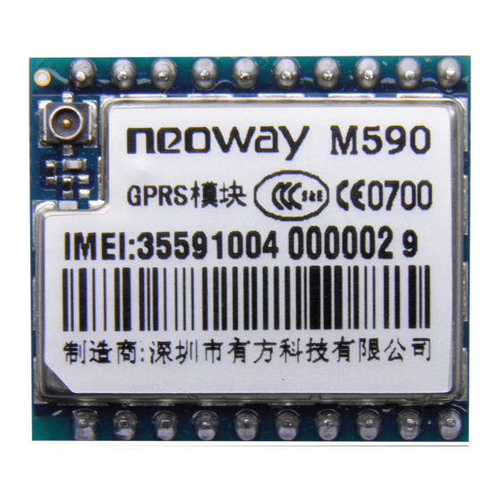
Specifications and Encapsulation Specifications M590 Dimensions 27.6 mm x 21.6 mm x 2.6 mm (H x W x D) Weight 2.6 g Encapsulation 21-pin LCC Figure 2-1 Top view of the M590 module GPRS_ANT ON/OFF VBAT VBAT RESET M590 LIGHT ADC_IN... -
Page 10: Pin Definition
M590 GPRS Module Hardware User Guide Pin Definition Table 2-1 M590 pin definition Name Function Reset Level Feature Remarks Status Power Supply and Switch Interfaces Main power supply 3.5 V to 4.3 V (3.9 V 2, 3 VBAT input is recommended) Supply power for IO 2.8 V power supply... - Page 11 M590 GPRS Module Hardware User Guide 2.38<V <2.8 SMS and Incoming Call Ring 0<V <0.6 Detect incoming 2.1<V <3.1 RING Ring output I/PD SMS messages or 0<V <0.42 calls 2.38<V <2.8 ADCDetecting Detectable voltage ADC_IN 10-bitADC input range: 0 V to 2.8 V...
-
Page 12: Pcb Foot Print
M590 GPRS Module Hardware User Guide PCB Foot Print LCC packaging is adopted to package the pins of the M590 module. Figure 2-2 shows the recommended PCB foot print. Figure 2-2 PCBfoot print recommended for M590 (unit: mm) 2.35 2.54 Copper Cut D=2.0... -
Page 13: Interface Design
M590 GPRS Module Hardware User Guide 3 Interface Design Power Supply and Switch Interfaces Table 3-1 Power supply and switch interface Signal Function Remarks VBAT Main power supply input 3.5 V to 4.3 V (3.9 V is recommended) VDD_EXT 2.8 V power supply output Loading capability <... -
Page 14: Figure 3-2 Capacitors Used For The Power Supply
M590 GPRS Module Hardware User Guide Figure 3-2shows a recommended power supply design for the module. Figure 3-2 Capacitors used for the power supply In the circuit, you can use TVS at D1 to enhance the performance of the module during a burst. SMF5.0AG (Vrwm=5V&Pppm=200W) is recommended.A large bypass tantalum capacitor (220 μF or 100μF) or... -
Page 15: Figure 3-4 Reference Design Of Power Supply Controlled By P-Mosfet
M590 GPRS Module Hardware User Guide Figure 3-4 Reference design of power supply controlled by p-MOSFET VCC_IN_3.9V VBAT 10 uF 0.1 uF 100pF 33 pF 470 uF 100K 10 uF 0.1 uF GPRS_EN Q2 is added to eliminate the need for a high enough voltage level of the host GPIO.In case that the GPIO can output a high voltage greater than VCC_IN_3.9V - |V... -
Page 16: Vdd_Ext
Never use a diode to make the drop voltage between a higher input and module power. Otherwise, Neoway will not provide warranty for product issues caused by this. In this situation, the diode will obviously decrease the module performances, or result in unexpected restarts, due to the forward voltage of diode will vary greatly in different temperature and current. -
Page 17: Figure 3-6 Power-On Procedure
2 seconds later it will shut down. Another approach to turn off the module is using AT commands. For details, see M590 GPRS Module AT Commands. Figure 3-7 shows the power-off procedure of the module. -
Page 18: Figure 3-8 Reference Circuit For Power-On/Off Control
M590 GPRS Module Hardware User Guide Figure 3-8 Reference circuit for power-on/off control ON/OFF GPRS Module Figure 3-9 Reference circuit for power-on/off controlled by high level ON/OFF 4.7K GPRS Module USER_ON In Figure 3-9, high level takes effect for ON/OFF on the user side (USER_ON) after level shifting. -
Page 19: Reset
M590 GPRS Module Hardware User Guide 3.1.4 RESET You can reset the module by keeping the RESET pin low level for more than 100 ms.The pin is pulled up by an internal resistor and the typical high level is 2.8 V. The RESET pin can be left disconnected if not used. If you use 3.3 V IO system, you are advised to separate it by using triode. -
Page 20: Figure 3-12 Recommended Circuit For The Communication Between 3.3V Mcu And Uart
M590 GPRS Module Hardware User Guide If the UART is interfacing with a MCU that has 3.3V logic levels, it is recommended that you add a level shifting circuit outside of the module. Figure 3-12 Recommended circuit for the communication between 3.3V MCU and UART VDD_EXT 0.1 uF... -
Page 21: Dtr And Ring
M590 GPRS Module Hardware User Guide In Figure 3-13, INPUT is connected to UTXD of the MCU and VCC_IN is connected to the 5 V power supply of the MCU. OUTPUT is connected to URXD of the module and VCC_OUT is connected to VDD_EXT(2.8V) of the module.If the circuit is far away from the VDD_EXTpin, add a 0.1 μF decoupling... -
Page 22: Ring Signal Indicator
SIM card data IO Internal pull-up M590 supports 3.0 V and 1.8 V SIM cards. VSIM supplies power for SIM card with 30mA. SIM_DATA is internally pulled up by a resistor. External pull-up resistor is not needed. SIM_CLK can work at several frequenciesat 3.25MHz typically. -
Page 23: Figure 3-16 Reference Design Of Sim Card Interface
M590 GPRS Module Hardware User Guide GPRS Module Hardware User Guide Figure 3-16 Reference design of SIM card interface SIM_DATA SIM_CLK DATA DATA SIM_RST VSIM GPRS SIM卡 1 uF Module ESD protectors, such as ESD diodes (lower than 33 pF) or... -
Page 24: Running Led Indicator
When the module is running, the LED indicator is driven by the LIGHT to indicate different module status with its various blink behaviors. You can set the blink mode by AT commands. For more details, see M590 GPRS Module AT Command Set. -
Page 25: Rf Interface
M590 GPRS Module Hardware User Guide RF Interface 3.6.1 RF Design and PCB Layout A 50 Ω antenna is required. VSWR ranges from 1.1 to 1.5. The antenna should be well matched to achieve best performance. It should be installed far away from high speed logic circuits, DC/DC power, or any other strong disturbing sources. -
Page 26: Figure 3-20 Rf Layout Reference
M590 GPRS Module Hardware User Guide Figure 3-20 RF layout reference Separate the copper-removing Ensure complete ground at both area from the RF route by sides of the 20 pin. Avoid ground. ground at only one side. Remove the copper from the... -
Page 27: Recommended Rf Connection
M590 GPRS Module Hardware User Guide 3.6.2 Recommended RF Connection If you adopts RF cables for connections, the GSC RF connector MM9329-2700RA1 from Murata is recommended. Figure 3-22 shows the encapsulation specifications. Figure 3-22 Encapsulation specifications of Murata RF connector... -
Page 28: Electric Features And Reliability
M590 GPRS Module Hardware User Guide 4 Electric Features and Reliability Electric Feature Table 4-1 Electric feature of the module Parameter Minimum Value Typical Value Maximum Value 3.5V 3.9V 4.3V VBAT Vout 2.8V VDD_EXT Iout 50mA Vout 2.3V 2.8V 3.1V Iout -0.3V... -
Page 29: Current
M590 GPRS Module Hardware User Guide Current Table 4-3 Current feature Testing Result Parameter Testing Conditions (Average Current) Testing voltage 3.9 V Agilent power supply Idle mode Set the instrument and power on the module. 18mA Power on the module or use AT command to shut... - Page 30 M590 GPRS Module Hardware User Guide ±8KV ±15KV ±8KV ±15KV Cover ±4KV ±8KV URXD/UTXD ±4KV ±8KV Others Copyright © Neoway Technology Co., Ltd...
-
Page 31: Rf Features
M590 GPRS Module Hardware User Guide 5 RF Features Work Band Table 5-1 Work band Work Band Uplink Downlink EGSM900 880~915MHz 925~960MHz DCS1800 1710~1785MHz 1805~1880MHz Transmitting Power and Receiving Sensitivity 5.2.1 Transmitting Power Table 5-2 Transmitting power (EGSM900) Transmitting Power Threshold Range ±2 dBm... -
Page 32: Receiving Sensitivity
M590 GPRS Module Hardware User Guide ±3dBm 26 dBm ±3dBm 24 dBm ±3dBm 22 dBm ±3dBm 20 dBm ±3dBm 18 dBm ±3dBm 16 dBm ±3dBm 14 dBm ±3dBm 12 dBm ±4Bm 10 dBm ±4Bm 8 dBm ±4Bm 6 dBm ±4dBm 4 dBm ±5dBm... -
Page 33: Mounting The Module Onto The Application Board
Neoway adopts trays to hold our modules to facilitate mounting. You can just put the tray in fixed direction on your machine. For more details about the storage and mounting of our modules, refer toReflow Soldering Guide for Neoway SMD Modules V1.2. -
Page 34: Abbreviations
M590 GPRS Module Hardware User Guide 8 Abbreviations Analog-Digital Converter Automatic Frequency Control Automatic Gain Control Acknowledged multirate (speech coder) Circuit Switched Data Central Processing Unit Digital Audio interface Digital-to-Analog Converter Data Communication Equipment Digital Signal Processor Data Terminal Equipment... - Page 35 Voltage Standing Wave Ratio Modular Approal: The M590 module is designed to comply with the FCC statement. FCC ID is PJ7-125X. The host system using M590, should have label indicated it contain modular’s FCC ID PJ7-125X. This radio module must not installed to co-locate and operating simultaneously with other radios in host system , additional testing and equipment authorization may be required to operating simultaneously with other radio.
- Page 36 M590 GPRS Module Hardware User Guide terference to radio communications. However, there is no guarantee that interference will not occur in a particular installation. If this equipment does cause harmful interference to radio or television reception, which can be determined by turning the equipment off and on, the user is encouraged to try to correct t he interference by one or more of the following measures: -Reorient or relocate the receiving antenna.
Need help?
Do you have a question about the M590 and is the answer not in the manual?
Questions and answers