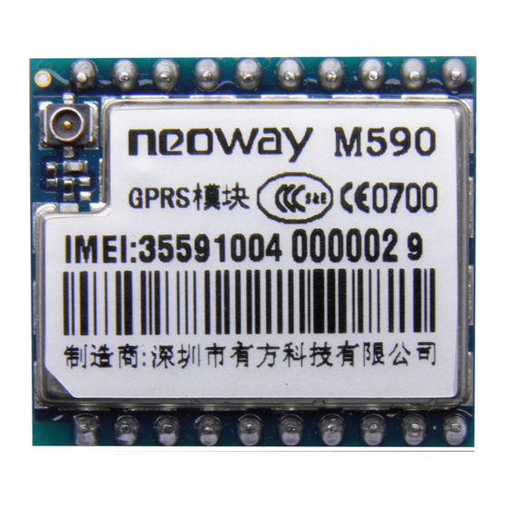
Sign In
Upload
Manuals
Brands
Neoway Manuals
Control Unit
M590
Neoway M590 Manuals
Manuals and User Guides for Neoway M590. We have
3
Neoway M590 manuals available for free PDF download: At Command Manual, At Command Set, Hardware User's Manual
Neoway M590 At Command Manual (70 pages)
AT COMMAND SETS
Brand:
Neoway
| Category:
GSM/GPRS Modules
| Size: 1.22 MB
Table of Contents
Table of Contents
4
Get Sequence Number:+Cgsn
7
Get International Mobile Subscriber Identification:+CIMI
7
Get SIM Card Identification:+CCID
8
Get Version:+ Getvers
8
Repeat the Previous Command:a
8
Get the Modules Model :+Cgmm
9
Get the Module's Information:I
9
Echo:e
10
Display the Current Configuration:&V
10
Save Current Configuration:&W
11
Check the Modules Status :+Cpas
12
Check Network Registration Status:+Creg
12
Power Off:+Cpwroff
13
Set Module Function:+Cfun
13
Low-Power Set:+Enpwrsave
15
Clock:+Cclk
15
Set the Modules Baud Rate :+Ipr
16
Input PIN Code:+Cpin
16
PIN Enable and Check Function:+Clck
17
PIN Change the Password:+Cpwd
18
Parity Check:+Icf
19
Multiplexed Mode:+Cmux
19
Extended ERROR Report:+Ceer
21
Set Error Indication Message:+Cmee
21
Signal Intensity:+Csq
23
Network Selection:+Cops
23
Set Band:+Xbandsel
25
Choose SMS Service:+Csms
26
Primary SMS Storage:+Cpms
26
Set SMS Mode:+Cmgf
27
Set te Character Sets: +CSCS
28
Set Message Indication Format: + CNMI
28
Read Message:+Cmgr
29
Message Sending:+Cmgs
31
Message List:+Cmgl
31
Write Message:+Cmgw
33
Send Stored Message:+Cmss
34
Delete Message:+Cmgd
34
Service Center Address:+Csca
35
Set Text Mode Parameters: +CSMP
35
Display Text Mode Parameter:+Csdh
36
Choose Cell Broadcast Message Type:+Cscb
37
Telephone Telephone Book Book Book Commands Commands Commands
38
Choose Phone Book Storage:+Cpbs
38
Read Phone Book:+Cpbr
38
Write Phone Book:+Cpbw
39
Find Phone Book:+Cpbf
39
Gain Native Number:+Cnum
40
Call Diverting:+Ccfc
42
Call Waiting:+Ccwa
42
Call Hold and Three-Way-Call:+Chld
43
Set Pdpformat:+Cgdcont
44
Send USSD Data:+Cusd
44
Data Mode and at Mode Switch Settings:&D2
45
Data Mode Switch to at Mode
45
AT Mode Switched to Data Mode:o
46
User Authentication: +XGAUTH
46
Establish PPP Link:+XIIC
48
Select Internal or External Protocol Stack:+Xisp
48
Tcp/Ip at at Commands Commands
48
Establish TCP Link:+Tcpsetup
49
Send TCP Data:+Tcpsend
49
Receive TCP Data:+Tcprecv
50
Close TCP Link:+Tcpclose
50
Establish UDP Link:+Udpsetup
51
Send UDP Data:+Udpsend
52
Receive UDP Data:+Udprecv
52
Close UDP Link:+Udpclose
53
Check TCP/UDP Link Status:+Ipstatus
53
Tcp/Ip at Commands Note
54
Check or Set Dns
55
Dns Dns(Domain Domain Domain Name Name Name Server Server Server)Commands Commands Commands
55
Check Ip Address
55
Setting the Server TCP Listener: +TCPLISTEN
56
Close Listening Links: +CLOSELISTEN
56
Close the Master Station Link: +CLOSECLIENT
57
Receive the Data from the Main Station: +TCPRECV(S)
57
The Data Sent to the Master Station: +TCPSENDS
57
Check Status of the Master Station Link: +CLIENTSTATUS
58
Set Module Signal Status: +SIGNAL
58
Setting External Protocol Stack Light Status: +GPRSSTATUS
59
Commands
60
Login FTP Server:+Ftplogin
60
Logout FTP Server:+Ftplogout
61
Download Data from FTP Server:+Ftpget
61
Upload Data to FTP Server:+Ftpput
62
Check FTP Status:+Ftpstatus
63
Appendix
64
At Command Flow Chart for Setting up Tcp Connect
64
At Command Setting and Checking Flow Chart for 'Sms Full
66
Sms General at Commands
67
Flow Chart for Sending Text Mode SMS
68
Flow Chart for Sending PDU Mode SMS
69
Low Consumption Mode Setting
69
Advertisement
Neoway M590 At Command Set (70 pages)
Brand:
Neoway
| Category:
Control Unit
| Size: 1.13 MB
Table of Contents
Table of Contents
4
Get Sequence Number:+Cgsn
7
Get International Mobile Subscriber Identification:+CIMI
7
Get SIM Card Identification:+CCID
8
Get Version:+ Getvers
8
Repeat the Previous Command:a
8
Get the Modules Model :+Cgmm
9
The Module Information :I
9
Echo:e
10
Display the Current Configuration:&V
10
Save Current Configuration:&W
11
Check the Modules Status :+Cpas
12
Check Network Registration Status:+Creg
12
Power Off:+Cpwroff
13
Set Module Function:+Cfun
13
Low-Power Set:+Enpwrsave
15
Clock:+Cclk
15
Set the Module's Baud Rate:+Ipr
16
Input PIN Code:+Cpin
16
PIN Enable and Check Function:+Clck
17
PIN Change the Password:+Cpwd
18
Parity Check:+Icf
19
Multiplexed Mode:+Cmux
19
Extended ERROR Report:+Ceer
21
Set Error Indication Message:+Cmee
21
Signal Intensity:+Csq
23
Network Selection:+Cops
23
Set Band:+Xbandsel
25
Sms Service Sms Service Service Commands Commands Commands
26
Choose SMS Service:+Csms
26
Primary SMS Storage:+Cpms
26
Set SMS Mode:+Cmgf
27
Set te Character Sets: +CSCS
28
Set Message Indication Format: + CNMI
28
Read Message:+Cmgr
29
Message List:+Cmgl
31
Message Sending:+Cmgs
31
Write Message:+Cmgw
33
Send Stored Message:+Cmss
34
Delete Message:+Cmgd
34
Service Center Address:+Csca
35
Set Text Mode Parameters: +CSMP
35
Display Text Mode Parameter:+Csdh
36
Choose Cell Broadcast Message Type:+Cscb
37
Telephone Telephone Book Book Book Commands Commands Commands
38
Choose Phone Book Storage:+Cpbs
38
Read Phone Book:+Cpbr
38
Find Phone Book:+Cpbf
39
Write Phone Book:+Cpbw
39
Gain Native Number:+Cnum
40
Call Diverting:+Ccfc
42
Call Waiting:+Ccwa
42
Call Hold and Three-Way-Call:+Chld
43
Set Pdpformat:+Cgdcont
44
Send USSD Data:+Cusd
44
Data Mode and at Mode Switch Settings:&D2
45
Data Mode Switch to at Mode
45
AT Mode Switched to Data Mode:o
46
User Authentication: +XGAUTH
46
Select Internal or External Protocol Stack:+Xisp
48
Establish PPP Link:+XIIC
48
Establish TCP Link:+Tcpsetup
49
Send TCP Data:+Tcpsend
49
Receive TCP Data:+Tcprecv
50
Close TCP Link:+Tcpclose
50
Establish UDP Link:+Udpsetup
51
Send UDP Data:+Udpsend
52
Receive UDP Data:+Udprecv
52
Close UDP Link:+Udpclose
53
Check TCP/UDP Link Status:+Ipstatus
53
Tcp/Ip at Commands Note
54
Check Ip Address
55
Check or Set Dns
55
Tcp Server
56
Setting the Server TCP Listener: +TCPLISTEN
56
Close Listening Links: +CLOSELISTEN
56
Close the Master Station Link: +CLOSECLIENT
57
Receive the Data from the Main Station: +TCPRECV(S)
57
The Data Sent to the Master Station: +TCPSENDS
57
Check Status of the Master Station Link: +CLIENTSTATUS
58
Set Module Signal Status: +SIGNAL
58
Setting External Protocol Stack Light Status: +GPRSSTATUS
59
Ftp at Commands
60
Login FTP Server:+Ftplogin
60
Logout FTP Server:+Ftplogout
61
Download Data from FTP Server:+Ftpget
61
Upload Data to FTP Server:+Ftpput
62
Check FTP Status:+Ftpstatus
63
At Command Flow Chart for Setting up Tcp Connect
64
At Command Setting and Checking Flow Chart for 'Sms Full
66
Sms General at Commands
67
Flow Chart for Sending Text Mode SMS
68
Flow Chart for Sending PDU Mode SMS
69
Low Consumption Mode Setting
69
Faq Faq
70
Neoway M590 Hardware User's Manual (36 pages)
GPRS module
Brand:
Neoway
| Category:
Control Unit
| Size: 0.7 MB
Table of Contents
Table of Contents
4
About this Document
7
Block Diagram
7
Overview
7
Specifications
8
Table 1-1 M590Specifications
8
1 Introduction to M590
7
2 Pin Description and PCB Foot Print
9
Specifications and Encapsulation
9
Figure 2-1 Top View of the M590 Module
9
Pin Definition
10
Table 2-1 M590 Pin Definition
10
PCB Foot Print
12
Figure 2-2 Pcbfoot Print Recommended for M590 (Unit: MM)
12
3 Interface Design
13
Power Supply and Switch Interfaces
13
Design Requirements
13
Figure 3-1 Current Peaks and Voltage Drops
13
Table 3-1 Power Supply and Switch Interface
13
Figure 3-2 Capacitors Used for the Power Supply
14
Figure 3-3 Reference Design of Power Supply Control
14
Figure 3-4 Reference Design of Power Supply Controlled by P-MOSFET
15
Vdd_Ext
16
Power-On/Offcontrol and Procedure
16
Figure 3-5 Reference Designs of Separated Power Supply
16
Figure 3-6 Power-On Procedure
17
Figure 3-7 Power-Off Procedure
17
Figure 3-8 Reference Circuit for Power-On/Off Control
18
Figure 3-9 Reference Circuit for Power-On/Off Controlled by High Level
18
Reset
19
Uart
19
Figure 3-10 Reset Circuitwith Triode Separating
19
Figure 3-11 Signal Connection between DCE and DTE
19
Table 3-2 UART
19
Figure 3-12 Recommended Circuit for the Communication between 3.3V MCU and UART
20
Figure 3-13 Recommended Circuit for the Communication between 5V MCU and UART
20
DTR and RING
21
DTR Pin
21
Table 3-3 DTR and RING Pins
21
RING Signal Indicator
22
SIM Card Interface
22
Figure 3-14 RING Indicator for Incoming Call
22
Figure 3-15 RING Indicator for SMS
22
Table 3-4 SIM Card Interface
22
Figure 3-16 Reference Design of SIM Card Interface
23
Figure 3-17 Reference of SIM Card Socket
23
Running LED Indicator
24
Figure 3-18 LED Indicator
24
Table 3-5 LED Indicator
24
RF Interface
25
RF Design and PCB Layout
25
Figure 3-19 Reference Design for Antenna Interface
25
Figure 3-20 RF Layout Reference
26
Figure 3-21 Reference RF Design When Pin 21 Is Not Used
26
Recommended RF Connection
27
Figure 3-22 Encapsulation Specifications of Murata RF Connector
27
4 Electric Features and Reliability
28
Electric Feature
28
Temperature
28
Table 4-1 Electric Feature of the Module
28
Table 4-2 Temperature Feature
28
Current
29
Esdprotection
29
Table 4-3 Current Feature
29
Table 4-4 ESD Feature of the Module
29
5 RF Features
31
Work Band
31
Transmitting Power and Receiving Sensitivity
31
Transmitting Power
31
Table 5-1 Work Band
31
Table 5-2 Transmitting Power (EGSM900)
31
Table 5-3 Transmitting Power (DCS1800)
31
Receiving Sensitivity
32
6 Mounting the Module Onto the Application Board
33
7 Package
33
8 Abbreviations
34
Advertisement
Advertisement
Related Products
Neoway M660
Neoway M590E
Neoway M590E V1
Neoway G2
Neoway N11 V2
Neoway N21 Series
Neoway N21-CN-011AS1
Neoway N21-EU-011AS1
Neoway N27
Neoway N51
Neoway Categories
Control Unit
GSM/GPRS Modules
Motherboard
Network Hardware
Network Router
More Neoway Manuals
Login
Sign In
OR
Sign in with Facebook
Sign in with Google
Upload manual
Upload from disk
Upload from URL