
Related Manuals for G&D DP1.2-Vision-CAT-AR


Summary of Contents for G&D DP1.2-Vision-CAT-AR
-
Page 1: Installation And Operation
Guntermann & Drunck GmbH www.gdsys.de G&D DP1.2-Vision-CAT Installation und Bedienung Installation and Operation A9100294-1.02... - Page 2 Zu dieser Dokumentation Diese Dokumentation wurde mit größter Sorgfalt erstellt und nach dem Stand der Technik auf Korrektheit überprüft. Für die Qualität, Leistungsfähigkeit sowie Marktgängigkeit des G&D-Produkts zu einem bestimmten Zweck, der von dem durch die Produktbeschreibung abgedeck- ten Leistungsumfang abweicht, übernimmt G&D weder ausdrücklich noch still- schweigend die Gewähr oder Verantwortung.
- Page 3 FCC Statement The devices named in this manual comply with Part 15 of the FCC Rules. Opera- tion is subject to the following two conditions: (1) the devices may not cause harm- ful interference, and (2) the devices must accept any interference received, including interference that may cause undesired operation.
-
Page 4: Table Of Contents
Inhaltsverzeichnis Inhaltsverzeichnis Sicherheitshinweise ..................1 Die DP1.2-Vision-CAT-Serie ................3 Verfügbare Gerätevarianten ................3 Optionaler Anschluss an einen KVM-Matrixswitch ..........3 Lieferumfang ....................4 Installation ....................... 5 Vorbereitung ...................... 5 Installation des Rechnermoduls ................6 Installation des Arbeitsplatzmoduls ..............10 Inbetriebnahme ....................14 Startvorgang .................... - Page 5 Inhaltsverzeichnis Konfigurationseinstellungen (Fortsetzung) Reduzierung der Farbtiefe der zu übertragenden Bilddaten ......35 Verwendung des Freeze-Modus ..............36 USB-HID-Modus auswählen ..............38 Unterstützung für Spezialtastaturen ............40 Änderung des Scancode-Sets einer PS/2-Tastatur ........41 Tastatur für Start des Arbeitsplatzmoduls erforderlich ......... 43 Wartezeit des Bildschirmschoners einstellen ..........
-
Page 6: Sicherheitshinweise
Sicherheitshinweise Sicherheitshinweise Bitte lesen Sie die folgenden Sicherheitshinweise aufmerksam durch, bevor Sie das G&D-Produkt in Betrieb nehmen. Die Hinweise helfen Schäden am Produkt zu ver- meiden und möglichen Verletzungen vorzubeugen. Halten Sie diese Sicherheitshinweise für alle Personen griffbereit, die dieses Produkt benutzen werden. - Page 7 Sicherheitshinweise Hinweise zum Umgang mit Lithium-Knopfzellen Dieses Produkt enthält eine Lithium-Knopfzelle. Ein Austausch durch den Anwender ist nicht vorgesehen! VORSICHT: Es besteht Explosionsgefahr, wenn die Batterie durch einen falschen Batterie-Typ ersetzt wird. Entsorgen Sie gebrauchte Batterien umweltgerecht. Gebrauchte Batterien dürfen nicht in den Hausmüll geworfen werden.
-
Page 8: Die Dp1.2-Vision-Cat-Serie
Verfügbare Gerätevarianten Innerhalb der -Serie sind verschiedene Varianten verfügbar, die die DP1.2-Vision-CAT zusätzliche Übertragung von USB 2.0-Signalen erlauben: Modell Videokanäle USB 2.0 DP1.2-Vision-CAT-AR nicht unterstützt Full Speed DP1.2-Vision-CAT-ARU DP1.2-Vision-CAT-ARU2 Hi-Speed Optionaler Anschluss an einen KVM-Matrixswitch Die Rechnermodule ( ) sowie die Arbeitsplatzmodule ( ) der DP1.2-Vision-CAT... -
Page 9: Lieferumfang
Lieferumfang Lieferumfang Standardlieferumfang der DP1.2-Vision-CAT-Serie Das KVM-Extender-System besteht aus einem Rechner- ( ) und DP1.2-Vision-CAT-CPU einem Arbeitsplatzmodul ( DP1.2-Vision-CAT-CON Zusätzlich befindet sich folgendes Zubehör im Lieferumfang der Geräte: 2 × Stromversorgungskabel (PowerCable-2 Standard) 1 × Videokabel (DP-Cable-M/M-2) 1 × USB-Gerätekabel (USB-AM/BM-2) ... -
Page 10: Installation
Installation Installation Vorbereitung WICHTIG: Stellen Sie bei der Standortwahl der Geräte sicher, dass die zulässige Umgebungstemperatur (siehe Technische Daten auf Seite 56) in der unmittelbaren Nähe eingehalten und nicht durch andere Geräte beeinflusst wird. WICHTIG: Bei Gerätevarianten mit Lüftungsöffnungen ist eine Verdeckung der Lüftungsöffnungen zu vermeiden. -
Page 11: Installation Des Rechnermoduls
Installation Installation des Rechnermoduls An das Rechnermodul schließen Sie den Rechner an, dessen DP1.2-Vision-CAT-CPU Signale an den entfernten Arbeitsplatz übertragen werden. Falls gewünscht, können Sie einen lokalen Arbeitsplatz an das Rechnermodul anschließen. Verbindung mit einem lokalen Netzwerken herstellen Power Network Fan In Red. - Page 12 Installation Videoausgang des Rechners anschließen USB 2.0 Trans. USB 2.0 CPU RS232 Keyb./Mouse Transmission DP Out DP CPU Line USB CPU Keyb. CPU Red. Power DisplayPort CPU: Verbinden Sie den Videoausgang des Rechners mit dieser Schnitt- stelle. Verwenden Sie hierzu das Kabel DP-Cable-M/M-2. Audio- und RS232-Schnittstellen verbinden USB 2.0 Trans.
- Page 13 Installation Zusätzliche Schnittstellen der ARU2-Variante verbinden USB 2.0 Trans. USB 2.0 CPU RS232 Keyb./Mouse Transmission DP Out DP CPU Line USB CPU Keyb. CPU Red. Power USB 2.0 CPU: Verbinden Sie eine USB-Schnittstelle des Rechners mit dieser Schnitt- stelle. Verwenden Sie hierzu das Kabel USB-AM/BM-2. USB 2.0 Trans.
- Page 14 Installation Optional: Lokalen Arbeitsplatz anschließen USB 2.0 Trans. USB 2.0 CPU RS232 Keyb./Mouse Transmission DP Out Line USB CPU Keyb. CPU Red. Power HINWEIS: Die Tastatur des lokalen Arbeitsplatzes können Sie wahlweise als PS/2- oder USB-Gerät anschließen. TIPP: Verwenden Sie den Adapter (A6400043) zum gleichzeitigen MD6M-2xMD6F Anschluss einer PS/2-Tastatur und einer PS/2-Maus.
-
Page 15: Installation Des Arbeitsplatzmoduls
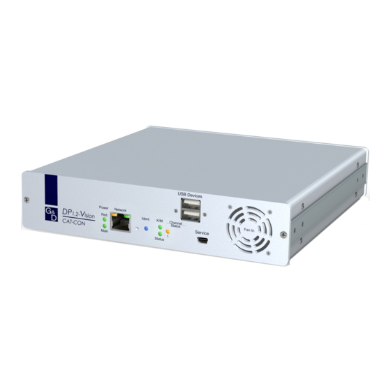
Installation Installation des Arbeitsplatzmoduls An das Arbeitsplatzmodul schließen Sie den entfernten DP1.2-Vision-CAT-CON Arbeitsplatz an. An diesem Arbeitsplatz können Sie den am Rechnermodul ange- schlossenen Rechner bedienen. Verbindung mit einem lokalen Netzwerk herstellen USB Devices Power Network Fan In Red. Ident. Ch. - Page 16 Installation Schließen Sie die PS/2-Tastatur des Arbeitsplatzes an. Keyb.: Mouse: Schließen Sie die PS/2-Maus des Arbeitsplatzes an. Monitor des Arbeitsplatzes anschließen USB 2.0 Trans. RS232 Generic USB 2.0 Devices Transmission DP Out Line In Speaker Keyb./Mouse Keyb./Mouse Red. Power DP Out: Schließen Sie hier den Monitor des Arbeitsplatzes an.
- Page 17 Installation Audio- und RS232-Schnittstellen verbinden USB 2.0 Trans. RS232 Generic USB 2.0 Devices Transmission DP Out Line In Speaker Keyb./Mouse Keyb./Mouse Red. Power Line In: Schließen Sie hier gegebenenfalls ein Mikrofon an. Schließen Sie die Lautsprecher oder ein anderes Audioausgabegerät des Speaker: Arbeitsplatzes an.
- Page 18 Installation Stromversorgung herstellen USB 2.0 Trans. RS232 Generic USB 2.0 Devices Transmission DP Out Line In Speaker Keyb./Mouse Keyb./Mouse Red. Power Main Power: Stecken Sie ein mitgeliefertes Kaltgerätekabel ein. Red. Power: Stecken Sie ein mitgeliefertes Kaltgerätekabel ein. Hierdurch wird eine zweite, redundante Stromversorgung des Arbeitsplatzmoduls erreicht.
-
Page 19: Inbetriebnahme
Inbetriebnahme Inbetriebnahme Nach der ordnungsgemäßen Installation der KVM-Extender können diese sofort in Betrieb genommen werden. Beachten Sie folgende Einschaltreihenfolge bei der Erstinbetriebnahme der Module: 1. Schalten Sie das Arbeitsplatzmodul ein. DP1.2-Vision-CAT-CON 2. Schalten Sie das Rechnermodul ein. DP1.2-Vision-CAT-CPU 3. Schalten Sie den, am Rechnermodul angeschlossenen, Rechner ein. HINWEIS: Die empfohlene Einschaltreihenfolge für die Erstinbetriebnahme stellt sicher, dass die KVM-Extender die Eigenschaften des angeschlossenen Monitors... -
Page 20: Erstkonfiguration Der Netzwerkeinstellungen
Erstkonfiguration der Netzwerkeinstellungen Erstkonfiguration der Netzwerk- einstellungen Grundlegende Voraussetzung für den Zugriff auf die Webapplikation des KVM- Extenders ist die Konfiguration der Netzwerkeinstellungen des Rechner- und des Arbeitsplatzmoduls. HINWEIS: Im Auslieferungszustand sind folgende Einstellungen vorausgewählt: IP-Adresse der Netzwerkschnittstelle A: Bezug der Adresse via DHCP (Fallback: IP-Adresse 192.168.0.1) -
Page 21: Konfiguration Der Globalen Netzwerkeinstellungen
Erstkonfiguration der Netzwerkeinstellungen Netmask: Geben Sie die Netzmaske des Netzwerkes an. Im Betriebsmodus DHCP ist keine Eingabe möglich. Connection type: Betätigen Sie die -Taste, um festzulegen, ob der Verbindungs- typ automatisch ( Auto ) mit der Gegenstelle ausgehandelt wer- den soll oder wählen Sie einen der verfügbaren Typen aus. 5. -
Page 22: Bedienung
Bedienung Bedienung Den am Rechnermodul DP1.2-Vision-CPU angeschlossene Rechner können Sie sowohl am entfernten Arbeitsplatz des Arbeitsplatzmoduls als auch am lokalen Arbeitsplatz des Rechnermoduls bedienen. Nach der Inbetriebnahme ist die Bedienung des Rechners für beide Arbeitsplätze freigeschaltet. HINWEIS: Die Monitore des entfernten und des lokalen Arbeitsplatzes zeigen in der Standardeinstellung gleichzeitig immer das gleiche Bild an. -
Page 23: Steckdose Schalten
Bedienung Sofort nach Betätigung dieser Tastenkombination sind die Eingabegeräte des kon- kurrierenden Arbeitsplatzes deaktiviert. Durch erneutes Ausführen der Tasten- kombination am aktiven Arbeitsplatz, wird die Bedienung des KVM-Extenders wieder für beide Arbeitsplätze freigeschaltet. HINWEIS: Nach Aktivierung der exklusiven Bedienung des KVM-Extenders an einem Arbeitsplatz blinken an der Tastatur des gesperrten Arbeitsplatzes abwech- selnd die Caps Lock- und die Num- sowie Scroll Lock-LEDs. -
Page 24: Verwendung Des Reset-Tasters
Verwendung des Reset-Tasters Verwendung des Reset-Tasters Zwischen der Identification-LED und den Power-LEDs auf der Frontseite des Rech- ner- sowie des Arbeitsplatzmoduls ist der Reset-Taster platziert. Mit diesem Taster ist sowohl die Wiederherstellung der Standardeinstellungen des Moduls als auch die temporäre Deaktierung dessen Netzfilterregeln möglich. HINWEIS: Um die versehentliche Betätigung des Tasters zu vermeiden, ist dieser hinter einer Bohrung in der Frontblende platziert. -
Page 25: Temporäre Deaktivierung Der Netzfilterregeln
Verwendung des Reset-Tasters Temporäre Deaktivierung der Netzfilterregeln Im Auslieferungszustand des KVM-Extenders haben alle Netzwerk-Rechner Zugriff auf die IP-Adresse des Extenders (offener Systemzugang). Über die Webapplikation können Sie Netzfilterregeln erstellen, um den Zugang zum Extender gezielt zu kontrollieren. Sobald eine Netzfilterregel erstellt ist, wird der offene Systemzugang deaktiviert und alle eingehenden Datenpakete mit den Netzfilterregeln verglichen. -
Page 26: Konfiguration
Konfiguration Konfiguration Die Konfiguration des KVM-Extenders kann wahlweise im On-Screen-Display (OSD) oder über die Webapplikation Config Panel durch den Anwender geändert werden: Das On-Screen-Display wird auf dem Monitor des Arbeitsplatzes angezeigt. Die meisten Konfigurationseinstellungen können Sie im OSD direkt am Arbeitsplatz einstellen. -
Page 27: Bedienung Des On-Screen-Displays Am Arbeitsplatz
Konfiguration Funktion Standardeinstellung Seite Farbe der Informationseinblendung ändern hellgrün Anzeige der Informationseinblendung temporär Transparenz des On-Screen-Displays einstellen mittleres Durchscheinen Position der Informationseinblendung ändern links oben Position des On-Screen-Displays ändern zentriert Die grundlegende Bedienung des On-Screen-Displays (s. Seite 22) und der Webapplikation (s. -
Page 28: Bedienung Des On-Screen-Displays
Konfiguration Kopfzeile Hier wird der Titel des aktuellen Menüs angezeigt. Listenfeld Im Listenfeld werden die Menüeinträge des ausgewählten Menüs aufgeführt. Zu unterscheiden sind zwei Arten von Menüeinträgen: Menüpunkte mit Untermenü: Diese Einträge werden mit drei Punkten (…) in der rechten Spalte dargestellt. -
Page 29: Grundlegende Bedienung Der Webapplikation
Konfiguration Grundlegende Bedienung der Webapplikation Die Webapplikation bietet eine grafische Benutzeroberfläche zur Konfigu- Config Panel ration und Überwachung des KVM-Extenders. Die Webapplikation verwendet die Java Web Start-Technologie. Diese Technologie erlaubt die Ausführung der Java-Anwendung, unabhängig von den Einstellungen und der Java-Kompatibilität des Webbrowsers. HINWEIS: Grundlegende Informationen zu den Systemvoraussetzungen, der erfor- derlichen Konfiguration der Netzwerkschnittstellen der... -
Page 30: Benutzerauthentifizierung Gegenüber Der Webapplikation
Konfiguration Benutzerauthentifizierung gegenüber der Webapplikation Nach der Bestätigung der Zertifikate wird die Login-Maske angezeigt. Config Panel So loggen Sie sich in die Webapplikation ein: 1. Geben Sie in die Login-Maske folgende Daten ein: Benutzername: Geben Sie Ihren Benutzernamen ein. Passwort: Geben Sie das Passwort Ihres Benutzerkontos ein. -
Page 31: Konfigurationseinstellungen
Konfiguration Konfigurationseinstellungen Änderung des Hotkeys Werden auf einem Rechner viele Anwendungsprogramme mit Tastenkombinatio- nen bedient oder verschiedene KVM-Geräte in einer Kaskade verwendet, ist die Zahl der „freien” Tastenkombinationen möglicherweise eingeschränkt. Falls ein Anwendungsprogramm oder ein anderes Gerät innerhalb der Kaskade den gleichen Hotkey verwendet, kann dieser geändert werden. -
Page 32: Änderung Der Osd-Taste
Konfiguration Änderung der OSD-Taste Der Hotkey zum OSD-Aufruf besteht aus mindestens einer Hotkey-Modifiziererta- ste (siehe Änderung des Hotkeys auf Seite 26) und einer zusätzlichen OSD-Taste, die vom Anwender innerhalb eines vorgegebenen Rahmens frei gewählt werden kann. Sowohl die Hotkey-Modifizierertaste Strg als auch die OSD-Taste können von Ihnen verändert werden. -
Page 33: On-Screen-Display Mit Doppeltem Tastendruck Starten
Konfiguration On-Screen-Display mit doppeltem Tastendruck starten Alternativ zum Öffnen des On-Screen-Displays (OSD) mit der Tastenkombination bzw. können Sie das OSD durch die zweifache, auf- Hotkey+Num Doppel-Hotkey+Num einanderfolgende Betätigung einer konfigurierten Taste öffnen. So (de)aktivieren Sie die Aktivierung des On-Screen-Displays mit doppeltem Tastendruck: 1. -
Page 34: Änderung Der Exklusiv-Taste
Konfiguration Änderung der Exklusiv-Taste Nach Betätigung der Tastenkombination für die exklusive Bedienung des Extenders sind die Eingabegeräte des konkurrierenden Arbeitsplatzes deaktiviert. Erst durch erneute Betätigung der Tastenkombination am aktiven Arbeitsplatz, wird die Bedie- nung des KVM-Extenders wieder für beide Arbeitsplätze freigeschaltet. Die Tastenkombination für die exklusive Bedienung besteht aus mindestens einer Hotkey-Modifizierertaste (siehe Änderung des Hotkeys auf Seite 26) und einer zusätzlichen Exklusiv-Taste, die vom Anwender innerhalb eines vorgegebenen Rah-... -
Page 35: Änderung Der Zeitspanne Der Eingabesperre
Konfiguration Änderung der Zeitspanne der Eingabesperre Wird an einem Arbeitsplatz eine Eingabe per Tastatur oder Maus durchgeführt, sperrt der KVM-Extender automatisch die Eingabegeräte des konkurrierenden Arbeitsplatzes. Die Sperre wird aufgehoben, wenn innerhalb der eingestellten Zeit- spanne der Eingabesperre (Standard: 1 Sekunde) keine weitere Eingabe am aktiven Arbeitsplatz erfolgt. -
Page 36: Berechtigung Für Exklusiven Zugriff Des Arbeitsplatzes
Konfiguration Berechtigung für exklusiven Zugriff des Arbeitsplatzes Erfolgt innerhalb der eingestellten Zeitspanne der automatischen Eingabesperre (Standard: 1 Sekunde) keine Eingabe am aktiven Arbeitsplatz, erlaubt der KVM- Extender in der Standardeinstellung auch dem anderen Arbeitsplatz die Bedienung des Extenders. Wird die Berechtigung für exklusiven Zugriff des Arbeitsplatzes in der Webapplika- tion eingeschaltet, können Anwender an einem solchen Arbeitsplatz mit der Tasten- kombination (Vorgabe:... -
Page 37: Änderung Der Videobetriebsart Der Arbeitsplätze
Konfiguration 1. Klicken Sie im Strukturbaum auf KVM-Extender > [Alle Extender] 2. Doppelklicken Sie das Rechnermodul des zu konfigurierenden KVM- Extenders. 3. Klicken Sie auf den Reiter , falls Sie die Berechtigung für den lokalen Lokal Arbeitsplatz (am -Modul) einstellen möchten. Klicken Sie auf den Reiter , falls Sie die Berechtigung für Remote >... - Page 38 Konfiguration So wählen Sie die Videobetriebsart eines Arbeitsplatzes: 1. Starten Sie das On-Screen-Display mit dem Hotkey Strg+Num (Standard). 2. Wählen Sie die Zeile Console setup und betätigen Sie die Eingabetaste , falls Sie die Videobetriebsart des entfernten Arbeitsplatzes (am -Modul) einstellen möchten.
-
Page 39: Auswahl Des Edid-Modus Des Kvm-Extenders
Konfiguration Auswahl des EDID-Modus des KVM-Extenders Die EDID-Informationen (Extended Display Identification Data) eines Monitors infor- mieren die Grafikkarte des angeschlossenen Rechners u. a. über verschiedene techni- sche Eigenschaften des Gerätes. Die Informationen werden vom KVM-Extender üblicherweise unverändert über Enhanced-DDC (Enhanced Display Data Channel) an den Rechner weitergeleitet. -
Page 40: Reduzierung Der Farbtiefe Der Zu Übertragenden Bilddaten
Konfiguration 1. Klicken Sie im Strukturbaum auf KVM-Extender > [Alle Extender] 2. Doppelklicken Sie das Rechnermodul des zu konfigurierenden KVM- Extenders. 3. Klicken Sie auf den Reiter Allgemein 4. Wählen Sie im Feld Edid-Profil zwischen folgenden Optionen: automatische Behandlung der EDID-Daten (Standard) [Auto] ... -
Page 41: Verwendung Des Freeze-Modus
Konfiguration 1. Klicken Sie im Strukturbaum auf KVM-Extender > [Alle Extender] 2. Doppelklicken Sie das Rechnermodul des zu konfigurierenden KVM- Extenders. 3. Klicken Sie auf den Reiter Allgemein 4. Wählen Sie im Feld Farbtiefe zwischen folgenden Optionen: 24 bit Übertragung der Bilddaten mit einer maximalen Farbtiefe von 24 bit (Standard) ... - Page 42 Konfiguration So konfigurieren Sie den Freeze-Modus: 1. Starten Sie das On-Screen-Display mit dem Hotkey Strg+Num (Standard). 2. Wählen Sie die Zeile Console setup und betätigen Sie die Eingabetaste Der Freeze-Modus wird für jeden Videokanal des Arbeitsplatzmoduls separat eingestellt. Bei Multichannel-Geräten können Sie die folgenden Optionen für jeden Videokanal separat eingestellen.
-
Page 43: Usb-Hid-Modus Auswählen
Konfiguration USB-HID-Modus auswählen Der KVM-Extender unterstützt verschiedene USB-Eingabegeräte. Die besonderen Eigenschaften eines bestimmten USB-Eingabegerätes können Sie nach Auswahl des spezifischen USB-Tastaturmodus nutzen. Alternativ zu den spezifischen USB-Tastaturmodi können Sie den Generic-HID Modus nutzen. In diesem Modus werden die Daten des USB-Gerätes an der ober- sten -Buchse des Arbeitsplatzmoduls unverändert an das Rechnermodul Keyb./Mouse... - Page 44 Konfiguration EINGABEGERÄT EINSTELLUNG Wacom Intuos5 S Wacom Int.5S Wacom Intuos5 M Wacom Int.5M Wacom Intuos5 L Wacom Int.5L In diesem Modus werden die Daten des USB-Gerätes an der Generic-HID-Modus: obersten -Buchse des Arbeitsplatzmoduls unverändert an das Rechner- Keyb./Mouse modul übertragen.
-
Page 45: Unterstützung Für Spezialtastaturen
Konfiguration So wählen Sie einen USB-HID-Modus: 1. Starten Sie das On-Screen-Display mit dem Hotkey (Standard). Strg+Num 2. Wählen Sie die Zeile Target setup und betätigen Sie die Eingabetaste 3. Wählen Sie die Zeile USB HID mode und betätigen Sie die -Taste zur Aus- wahl einer Option (s. -
Page 46: Änderung Des Scancode-Sets Einer Ps/2-Tastatur
Konfiguration 1. Klicken Sie im Strukturbaum auf KVM-Extender > [Alle Extender] 2. Doppelklicken Sie das Rechnermodul des zu konfigurierenden KVM- Extenders. 3. Klicken Sie auf den Reiter , falls Sie die Unterstützung einer Spezialta- Lokal statur für den lokalen Arbeitsplatz (am -Modul) einstellen möchten. - Page 47 Konfiguration So ändern Sie die Einstellung des Scancode-Sets: 1. Starten Sie das On-Screen-Display mit dem Hotkey (Standard). Strg+Num 2. Wählen Sie die Zeile Console setup und betätigen Sie die Eingabetaste , falls Sie das Scancode-Set für den entfernten Arbeitsplatz (am -Modul) ein- stellen möchten.
-
Page 48: Tastatur Für Start Des Arbeitsplatzmoduls Erforderlich
Konfiguration Tastatur für Start des Arbeitsplatzmoduls erforderlich In der Standardeinstellung startet das Arbeitsplatzmodul auch bei fehlender Tasta- tur. Alternativ kann das Arbeitsplatzmodul den Startvorgang bei fehlender Tastatur mit einem entsprechenden Hinweis unterbrechen. Sobald Sie eine Tastatur an das Arbeitsplatzmodul anschließen, wird der Startvorgang fortgesetzt. So konfigurieren Sie das Startverhalten bei fehlender Tastatur des Arbeitsplatz- moduls: 1. -
Page 49: Wartezeit Des Bildschirmschoners Einstellen
Konfiguration Wartezeit des Bildschirmschoners einstellen Der Bildschirmschoner schaltet nach einer von Ihnen einstellbaren Zeit der Inaktivi- tät des Benutzers die Bildschirmanzeige am Arbeitsplatz ab. HINWEIS: Diese Einstellung ist unabhängig von den Bildschirmschoner-Einstel- lungen des am Rechnermodul angeschlossenen Rechners. So stellen Sie die Wartezeit des Bildschirmschoners ein: 1. -
Page 50: Tastaturlayout Für Eingaben Innerhalb Des Osds Auswählen
Konfiguration Tastaturlayout für Eingaben innerhalb des OSDs auswählen Werden bei der Eingabe von Zeichen auf der Tastatur des Arbeitsplatzes andere Zeichen im On-Screen-Display angezeigt, ist das eingestellte Tastaturlayout der Tastatur nicht zutreffend. Stellen Sie in diesem Fall fest, welchem Tastaturlayout die angeschlossene Tastatur entspricht und konfigurieren Sie dieses anschließend in den Einstellungen des Arbeitsplatzmoduls. -
Page 51: Wiederherstellung Der Standardeinstellungen
Konfiguration Wiederherstellung der Standardeinstellungen HINWEIS: Diese Funktion kann ausschließlich über die Webapplikation ausge- führt werden. Mit dieser Funktion werden die Standardeinstellungen des KVM-Extenders wieder- hergestellt. Nach dem Ausführen der Funktion sind die auf Seite 21 aufgeführten Standardeinstellungen des KVM-Extenders wieder aktiv. So stellen Sie die Standardeinstellungen wieder her: HINWEIS: Öffnen Sie das lokale OSD des Arbeitsplatzmoduls mit dem... -
Page 52: Farbe Der Informationseinblendung Ändern
Konfiguration Farbe der Informationseinblendung ändern Informationseinblendungen werden standardmäßig in hellgrün angezeigt. Im per- sönlichen Profil können Sie die Farbe dieser Einblendungen anpassen. Neben der Standardfarbe light green (hellgrün) werden folgende Farben unterstützt: (schwarz) (dunkelrot) black dark red green (grün) dark yellow (dunkelgelb) (dunkelblau) (violett) -
Page 53: Anzeige Der Informationseinblendung
Konfiguration Anzeige der Informationseinblendung Informationseinblendungen erfolgen temporär (5 Sekunden) in der linken, oberen Ecke. TIPP: Ist die temporäre Informationseinblendung aktiv, können Sie mit der Tastenkombination Strg+Feststelltaste jederzeit eine Wiederholung der Einblen- dung erreichen. Alternativ zur temporären Einblendung kann die Informationseinblendung perma- nent erfolgen oder ausgeschaltet werden. -
Page 54: Transparenz Des On-Screen-Displays Einstellen
Konfiguration Transparenz des On-Screen-Displays einstellen In der Standardeinstellung wird das On-Screen-Display (OSD) mit einer mittleren Transparenz über dem Bildschirminhalt angezeigt. Den durch das OSD überlager- ten Teil des Bildschirminhalts können Sie „durch“ das OSD erkennen. Die Transparenzstufe können Sie einstellen oder ausschalten. So stellen Sie die Transparenzstufe des On-Screen-Displays ein: 1. -
Page 55: Position Der Informationseinblendung Ändern
Konfiguration Position der Informationseinblendung ändern In der Standardeinstellung erfolgen die Informationseinblendungen links oben auf dem Bildschirm des Arbeitsplatzes. Die Position der Einblendung können Sie nach Ihren Wünschen anpassen. So ändern Sie die Position der Informationseinblendung: 1. Starten Sie das On-Screen-Display mit dem Hotkey Strg+Num (Standard). -
Page 56: Weiterführende Informationen
Weiterführende Informationen Weiterführende Informationen Empfehlungen zu den Twisted-Pair-Kabeln Das Rechnermodul sowie das Arbeitsplatzmodul sind mit -Schnittstellen Transmission ausgestattet, über die folgende Daten zwischen den Modulen übertragen werden: Transmission: Tastatur, Video, Maus, Audio, RS232, USB 2.0 (nur -Variante) USB 2.0 Trans.: USB 2.0-Signale (nur ARU2 -Variante) -
Page 57: Übertragung Der Usb-Daten Der Aru2-Variante
Weiterführende Informationen Übertragung der USB-Daten der ARU2-Variante Die Übertragung der USB 2.0-Signale der ARU2 -Variante des DP1.2-Vision -Systems erfolgt ebenfalls über Twisted-Pair-Kabel der Kategorie 5e (oder höher). Abhängig von der Drahtstärke und des Kabeltyps der Twisted-Pair-Verkabelung können folgende Entfernungen zwischen dem Rechner- und dem Arbeitsplatzmo- dul überbrückt werden: Drahtstärke Kabeltyp... -
Page 58: Pin-Belegung Der Rs232-Buchse/Schnittstelle
Weiterführende Informationen Pin-Belegung der RS232-Buchse/Schnittstelle Die Pin-Belegungen des RS232-Steckers sowie der -Buchse zeigen die folgenden Abbildungen: Arbeitsplatzmodul Rechnermodul RS232-Stecker RS232-Buchse Die Tabelle zeigt die Zuordnung der verschiedenen Leitungen der Datenverbindung zu den entsprechenden Pins auf: Pin-Nr. Leitung Arbeitsplatz- Rechner- modul modul DCD (Data Carrier Detect) Eingang... -
Page 59: Statusanzeigen
Statusanzeigen Statusanzeigen Die LEDs an den Front- und Rückseiten des Rechner- und des Arbeitsplatzmoduls geben Ihnen die Möglichkeit, den Betriebsstatus des KVM-Extenders jederzeit zu kontrollieren. Bedeutung der LEDs an der Frontseite Bereich Farbe Status Bedeutung Ident. Ident. blau Leuchtet, sobald die LED über die Webapplikation aktiviert wurde. -
Page 60: Bedeutung Der Leds An Der Rückseite
Statusanzeigen Bedeutung der LEDs an der Rückseite Bereich Status Bedeutung Transmission gelb Kommunikation mit Gegenstelle hergestellt. blinkt Verbindung zur Gegenstelle hergestellt. Verbindung zur Gegenstelle nicht hergestellt. grün An Gegenstelle angemeldet. An Gegenstelle nicht angemeldet. USB 2.0 Trans. gelb USB-Host-Verbindung aufgebaut blinkt Energiesparmodus keine USB-Host-Verbindung... -
Page 61: Technische Daten
Technische Daten Technische Daten Allgemeine Eigenschaften der Serie DP1.2-VISION-CAT-SERIE Schnittstellen für Video: siehe spezifische Eigenschaften Rechner PS/2-Tastatur: 1 × PS/2-Buchse USB-Tastatur/Maus: 1 × USB-B-Buchse Audio: 3,5-mm-Klinkenbuchse (Line In) 3,5-mm-Klinkenbuchse (Line Out) USB 2.0: Variante -ARU Gemeinsame Übertragung der Signale der USB-Geräte sowie von Tastatur und Maus über USB-B-Buchse. - Page 62 Technische Daten DP1.2-VISION-CAT-SERIE Grafik Format: DisplayPort (DP 1.2a) Farbtiefe: 24 Bit Pixelkodierung: RGB 4:4:4 mit 24bpp/8bpc Videobandbreite: max. 600 MP / s, DisplayPort 4 Lanes, LBR, HBR, HBR2, SingleStreamTransport (SST) max. Auflösung 2560 × 1600 @ 60Hz pro Videokanal: ...
-
Page 63: Spezifische Eigenschaften Der Single-Channel-Geräte
Technische Daten Spezifische Eigenschaften der Single-Channel-Geräte DP1.2-VISION-CAT-CPU Schnittstellen für Monitor: 1 × DisplayPort-Buchse lokalen Arbeitsplatz Schnittstellen für Video: 1 × DisplayPort-Buchse Rechner Schnittstellen zum KVM, Audio und RS232: 1 × RJ45-Buchse Arbeitsplatzmodul Bei Variante -ARU werden zusätzlich die Signale der USB 2.0 -Geräte über dieses Kabel übertragen. -
Page 64: Strom- Und Leistungsaufnahme
Technische Daten Strom- und Leistungsaufnahme Hauptstromversorgung Gerätevariante Stromaufnahme Leistungsaufnahme (max.) AR-CPU 100-240V/60-50Hz/0.5-0.2A 21,0 W AR-CON 100-240V/60-50Hz/0.5-0.2A 23,2 W ARU-CPU 100-240V/60-50Hz/0.5-0.2A 21,6 W ARU-CON 100-240V/60-50Hz/0.7-0.3A 36,0 W ARU2-CPU 100-240V/60-50Hz/0.5-0.2A 24,0 W ARU2-CON 100-240V/60-50Hz/0.7-0.3A 38,0 W Redundante Stromversorgung Gerätevariante Stromaufnahme Leistungsaufnahme (max.) AR-CPU 12VDC/1.8A 19,4 W... -
Page 66: About This Manual
About this manual This manual has been carefully compiled and examined to the state-of-the-art. G&D neither explicitly nor implicitly takes guarantee or responsibility for the qual- ity, efficiency and marketability of the product when used for a certain purpose that differs from the scope of service covered by this manual. - Page 67 FCC Statement The devices named in this manual comply with Part 15 of the FCC Rules. Opera- tion is subject to the following two conditions: (1) the devices may not cause harm- ful interference, and (2) the devices must accept any interference received, including interference that may cause undesired operation.
- Page 68 Table of contents Table of contents Safety instructions .................... 1 The DP1.2-Vision-CAT series ................3 Available variants ....................3 Optional connection to a KVM matrix switch ............. 3 Package contents ....................4 Installation ....................... 5 Preparation ......................5 Installing the computer module ................6 Installing user modules ..................
- Page 69 Table of contents Configuration settings (continued) Reducing the colour depth of the image data to be transmitted ....35 Freeze mode ....................36 Selecting the USB-HID mode ..............38 Support of special keyboards ..............40 Changing the scancode set of PS/2 keyboards ..........41 Keyboard required to start the user module ..........
-
Page 70: Safety Instructions
Safety instructions Safety instructions Please read the following safety instructions carefully before you start operating the G&D product. The instructions well help in avoiding damages to the product and in preventing possible injuries. Keep this manual handy for all persons who will be using this product. Follow all warnings or operating instructions which are on the device or stated in this user manual. - Page 71 Safety instructions Instructions on how to handle Lithium button cells This product contains a lithium button cell. It is not intended to be replaced by the user! CAUTION: Risk of explosion if the battery is replaced by an incorrect battery type. Dispose of used batteries in an environmentally friendly manner.
-
Page 72: The Dp1.2-Vision-Cat Series
Available variants series provides further variants that additionally enable the DP1.2-Vision-CAT transmission of USB 2.0 signals: Variant Video channels USB 2.0 DP1.2-Vision-CAT-AR not supported full speed DP1.2-Vision-CAT-ARU DP1.2-Vision-CAT-ARU2 high speed Optional connection to a KVM matrix switch As an alternative to using the devices as stand-alone units, you can also connect the... -
Page 73: Package Contents
Package contents Package contents Standard package contents of the DP1.2-Vision-CAT series The KVM extender system consist of a computer module ( ) and DP1.2-Vision-CAT-CPU a user module ( DP1.2-Vision-CAT-CON Additionally, the package contents include the following accessories: 2 × power cable (PowerCable-2 Standard) ... -
Page 74: Installation
Installation Installation Preparation IMPORTANT: When choosing a location for the devices, please ensure to comply with the ambient temperature limit (see Technical data on page 56 ff.) close to the device. The ambient temperature limit must not be influenced by other devices. IMPORTANT: Do not cover the ventilation openings. -
Page 75: Installing The Computer Module
Installation Installing the computer module The computer, whose signals are transmitted to the remote console, is connected to computer module. If desired, connect a local console to the DP1.2-Vision-CAT-CPU computer module. Establishing a connection to a local network Power Network Fan In Red. - Page 76 Installation Connecting the computer’s video output USB 2.0 Trans. USB 2.0 CPU RS232 Keyb./Mouse Transmission DP Out DP CPU Line USB CPU Keyb. CPU Red. Power DP CPU: Use the DP-Cable-M/M-2 cable to connect the computer’s video output to this interface. Connecting audio and RS232 interfaces USB 2.0 Trans.
- Page 77 Installation Connecting further interfaces of ARU2 variants USB 2.0 Trans. USB 2.0 CPU RS232 Keyb./Mouse Transmission DP Out DP CPU Line USB CPU Keyb. CPU Red. Power Use the USB-AM/BM-2 cable to connect one of the computer’s USB USB 2.0 CPU: interfaces to this interface.
- Page 78 Installation Optional: Connecting a local console USB 2.0 Trans. USB 2.0 CPU RS232 Keyb./Mouse Transmission DP Out Line USB CPU Keyb. CPU Red. Power NOTE: The keyboard of the local console can either be a PS/2 or a USB device. ADVICE: Use the adapter (A6400043) to use a PS/2 keyboard and a...
-
Page 79: Installing User Modules
Installation Installing user modules The remote console is connected to the DP1.2-Vision-CAT-CON user module. The com- puter connected to the computer module can be operated from this console. Establishing a connection to a local network USB Devices Power Network Fan In Red. - Page 80 Installation Connecting the console monitor USB 2.0 Trans. RS232 Generic USB 2.0 Devices Transmission DP Out Line In Speaker Keyb./Mouse Keyb./Mouse Red. Power DP Out: Connect the console monitor. Establishing a connection to the computer module USB 2.0 Trans. RS232 Generic USB 2.0 Devices Transmission...
- Page 81 Installation Connecting audio and RS232 interfaces USB 2.0 Trans. RS232 Generic USB 2.0 Devices Transmission DP Out Line In Speaker Keyb./Mouse Keyb./Mouse Red. Power Line In: If required, connect a microphone to this interface. Speaker: Connect the speakers or another audio output device. Connect the serial end device to this interface.
- Page 82 Installation Establishing the power supply USB 2.0 Trans. RS232 Generic USB 2.0 Devices Transmission DP Out Line In Speaker Keyb./Mouse Keyb./Mouse Red. Power Main Power: Insert one of the supplied IEC cables here. Red. Power: To provide a second, redundant power supply, connect a portable power pack to this interface.
-
Page 83: Start-Up
Start-up Start-up After the proper installation of the KVM extenders they can be immediately put into operation. Mind the following activation sequence when starting the modules: 1. Turn on the user module DP1.2-Vision-CAT-CON 2. Turn on the computer module DP1.2-Vision-CAT-CPU 3. -
Page 84: Initial Configuration Of The Network Settings
Initial configuration of the network settings Initial configuration of the network settings A basic requirement to access the web application of the KVM extender is the con- figuration of the network settings of the computer module and the user module. NOTE: In the default settings the following settings are preselected: ... -
Page 85: Configuring Global Network Settings
Initial configuration of the network settings Netmask: Enter the netmask of the network. The operational mode DHCP does not allow making entries. Connection type: Press -Taste to define if the network interface and its com- munication partner are to negotiate the connection type automatically ( Auto ) or select one of the types available. -
Page 86: Operation
Operation Operation The computer connected to the computer module ( DP1.2-Vision-CPU ) can be operated at the remote console of the user module as well as at the local console of the com- puter module. After their initiation, both consoles are enabled to operate the computer. NOTE: The monitors of the remote and the local console of the KVM extender always display the same image at the same time. -
Page 87: Switching Power Outlets
Operation Immediately after pressing this hotkey, the input devices of the concurrent console are deactivated. By pressing the hotkey again at the active console, users at both consoles are again able to operate the KVM extender. NOTE: After the exclusive operation of the KVM extender has been activated at one console, the Caps Lock, Num as well as the Scroll Lock LEDs are blinking alter- nately at the keyboard of the locked console. -
Page 88: Using The Reset Button
Using the Reset button Using the Reset button The Reset button is located between the Identification LED and the Power LEDs on the front panel of the computer module and the user module. This button enables you to reset the default settings as well as to temporarily deacti- vate the netfilter rules. -
Page 89: Temporarily Deactivating The Netfilter Rules
Using the Reset button Temporarily deactivating the netfilter rules In the default status of the KVM extender, all network computers have access to the extender’s IP address (open system access). The web application enables you to create netfilter rules to control access to the extender. -
Page 90: Configuration
Configuration Configuration The configuration of the KVM extender can be changed either using the on-screen display (OSD) or the web application Config Panel The on-screen display is shown on the console monitor. Most configuration settings can be changed directly on the OSD of the console. ... -
Page 91: Operating The On-Screen Display At The Console
Configuration Function Default setting Page Changing the colour of the information display light green Information display temporary Adjusting the transparency of the on-screen display average transparency Changing the position of the information dispaly left upper corner Changing the position of the on-screen display centred The basic operation of the on-screen display (see page 22) and the web application Config Panel... -
Page 92: Operating The On-Screen Display
Configuration Header The header shows the title of the current menu. List field The list field shows the menu items of the selected menu. there are two types of menu items: Menu items with submenus: These items are displayed with three dots (…) in the right col- umn. -
Page 93: Basic Operation Of The Web Application
Configuration Basic operation of the web application Config Panel web application provides a graphical user interface to configure and monitor the KVM extender. The web application uses the Java Web Start technology. This technology allows the execution of the Java application, regardless of the settings and the Java compatibil- ity of the web browser. -
Page 94: User Authentication Against The Web Application
Configuration User authentication against the web application After the certificates are authenticated, the login box opens. Config Panel How to log on to the web application: 1. Enter the following data in the login box: Username: Enter your username. Password: Enter your user account password. -
Page 95: Configuration Settings
Configuration Configuration settings Changing hotkeys If many applications that use hotkeys are operated on one computer or if different KVM devices are used in one cascade, the number of available hotkeys might be restricted. In case an application or another device used within the cascade use the same hot- key, the hotkey can be changed. -
Page 96: Changing The Osd Key
Configuration Changing the OSD key The hotkey to open the OSD consists of at least one hotkey modifier (see Changing hotkeys on page 26) and an additional OSD key. You can freely select these keys from a number of selectable keys. You can change both the hotkey modifier Ctrl and the OSD key... -
Page 97: Opening The On-Screen Display Via Double Keypress
Configuration Opening the on-screen display via double keypress As an alternative to opening the on-screen display (OSD) with the hotkey Hot- key+Num Double hotkey+Num you can also open the OSD by pressing a configured key twice. How to enable/disable the activation of the on-screen display via double key- press: 1. -
Page 98: Changing The Exclusive Key
Configuration Changing the exclusive key After pressing the hotkey for the exclusive operation of the extender the input devices of the concurrent console are disabled. Only after pressing the hotkey again at the active console the KVM extender can again be operated by both consoles. The hotkey for the exclusive operation consists of at least one hotkey modifier (see Changing hotkeys on page 26) and an exclusive key. -
Page 99: Changing The Time Span Of The Input Lock
Configuration Changing the time span of the input lock When carrying out keyboard or mouse inputs at a console, the KVM extender auto- matically locks the input devices of the concurrent console. The lock is lifted if no input is made at the active console within the adjusted timing of the input lock (default: 1 second). -
Page 100: Right For Exclusive Access To The Console
Configuration Right for exclusive access to the console If no inputs are made at the active console during the adjusted time span of the auto- matic input lock (default: 1 second), the default settings of the KVM extender permit the other console to operate the extender. If the function right for exclusive console access is activated in the web application, you are able to operate the KVM extender exclusively by pressing the hotkey Hot-... -
Page 101: Changing The Video Mode Of Consoles
Configuration 1. Click on on the directory tree. KVM Extenders > [All Extenders] 2. Double-click the computer module of the KVM extender to be configured. 3. Click on the tab if you want to adjust the right for the local console (at Local module). - Page 102 Configuration How to select the video mode of a console: 1. Press Ctrl+Num (default) to open the on-screen display. 2. Select the row Console setup and press Enter if you want to adjust the video mode for the remote console (at the module).
-
Page 103: Selecting The Edid Mode Of The Kvm Extender
Configuration Selecting the EDID mode of the KVM extender EDID information (Extended Display Identification Data) of a monitor informs the gra- phics card of a connected computer about different technical device features. The information is usually transmitted via Enhanced-DDC (Enhanced Display Data Chan- nel) and without any alteration between KVM extender and computer. -
Page 104: Reducing The Colour Depth Of The Image Data To Be Transmitted
Configuration 1. Click on on the directory tree. KVM Extenders > [All Extenders] 2. Double-click the computer module of the KVM extender to be configured. 3. Click the tab. General 4. Under Edid profile select one of the following options: [Auto] ... -
Page 105: Freeze Mode
Configuration How to change the colour depth of the image data to be transmitted: 1. Press Ctrl+Num (default) to open the on-screen display. 2. Select the row and press Target setup Enter 3. Under press to select on of the following options: Color depth 24 Bit: ... - Page 106 Configuration How to configure the Freeze mode: 1. Press Ctrl+Num (default) to open the on-screen display. 2. Select the row Console setup and press Enter The Freeze mode is adjusted separately for each video channel of the user module. The following options can be adjusted separately for each video channel of multi-channel devices.
-
Page 107: Selecting The Usb-Hid Mode
Configuration Selecting the USB-HID mode The KVM extender supports various USB input devices. You can use the special fea- tures of a particular USB input device after selecting the specific USB keyboard mode. As an alternative to the specific USB keyboard modes, you can also use the generic mode. - Page 108 Configuration INPUT DEVICE SETTING Wacom Intuos5 S Wacom Int.5S Wacom Intuos5 M Wacom Int.5M Wacom Intuos5 L Wacom Int.5L In this mode, data of the USB device connected to the top Generic-HID mode: Keyb./ socket of the user module is transmitted to the computer module without Mouse being altered.
-
Page 109: Support Of Special Keyboards
Configuration How to select a USB-HID mode: 1. Press Ctrl+Num (default) to open the on-screen display. 2. Select the row Target setup and press Enter 3. Select the row USB HID mode and press key to select an option (see above). 4. -
Page 110: Changing The Scancode Set Of Ps/2 Keyboards
Configuration 1. Click on on the directory tree. KVM Extenders > [All Extenders] 2. Double-click the computer module of the KVM extender you want to con- figure. 3. Click on the tab if you want to adjust the support of a special key- Local board for the local console (at the module). - Page 111 Configuration How to change the setting of the scancode set: 1. Press Ctrl+Num (default) to open the on-screen display. 2. Select the row Console setup and press Enter if you want to adjust the scan- code set of the remote console (at the module).
-
Page 112: Keyboard Required To Start The User Module
Configuration Keyboard required to start the user module In the default settings, the user module starts even without a keyboard. As an alter- native, the user module can interrupt the starting process when no keyboard is con- nected. After you connect a keyboard to the user module, the starting process is continued. -
Page 113: Adjusting The Waiting Period Of The Screensaver
Configuration Adjusting the waiting period of the screensaver The screensaver turns off the display of the console after the user has been inactive for a defined period of time. NOTE: This setting does not affect the screensaver settings of the computer con- nected to the computer module. -
Page 114: Selecting A Keyboard Layout For Inputs Via Osd
Configuration Selecting a keyboard layout for inputs via OSD If the on-screen display shows other characters than entered on the console key- board, the keyboard layout has to be adjusted. Make sure which keyboard layout the connected keyboard uses and configure it in the settings of the user module. -
Page 115: Resetting The Default Settings
Configuration Resetting the default settings NOTE: This function can be carried out only via web application. This function is used to reset the default settings of the KVM extender. By perform- ing this function, the default settings mentioned on page 21 are reactivated. How to reset the default settings: NOTE: Open the local OSD of the user module by pressing the... -
Page 116: Changing The Colour Of The Information Display
Configuration Changing the colour of the information display By default, information display are shown in light green. You can adjust the colour of the information display in your personal profile. In addition to the default colour light green the following colours are supported: dark red black green... -
Page 117: Information Display
Configuration Information display Information displays are shown temporarily (5 seconds) in the upper left corner. ADVICE: If the temporary information display is active, you can press the hotkey Ctrl+Caps Lock to repeat the caption. The information display can also be shown permanently or it can be disabled How to change the setting of the information display: 1. -
Page 118: Adjusting The Transparency Of The On-Screen Display
Configuration Adjusting the transparency of the on-screen display In the default settings of the KVM switch, the on-screen display covers parts of the screen content. However, the parts of the screen contents covered by the OSD are still visible. You can adjust the transparency level or turn the transparency off. How to adjust the transparency of the on-screen display: 1. -
Page 119: Changing The Position Of The Information Dispaly
Configuration Changing the position of the information dispaly In the default configuration, the information display is shown at the left upper cor- ner of the console monitor. However, you can adjust the position to your liking. How to change the position of the information display: 1. -
Page 120: Further Information
Further information Further information Recommendations for twisted pair cables Both the computer module and the user module provide interfaces to Transmission transmit the following data between the modules. Transmission: keyboard, video, mouse, audio, RS232, USB 2.0 (only variant) USB 2.0 Trans.: USB 2.0 signals (only ARU2 variant) -
Page 121: Transmission Of Usb Data Of Aru2 Variants
Further information Transmission of USB data of ARU2 variants The USB 2.0 signals of the variant of the system are also transmit- ARU2 DP1.2-Vision ted via category 5e (or better) twisted pair cables. Depending on the wire gauge and the type of twisted pair cable, the following dis- tances can be bridged between computer module and user module: Wire gauge Cable type... -
Page 122: Pin Assignment Of The Rs232 Socket/Interface
Further information Pin assignment of the RS232 socket/interface The following figures show the pin assignments of the RS232 plug as well as the RS 232 socket: User module Computer module RS232 plug RS232 socket The table shows how the different lines of the data connection are assigned to the according pins: Pin no. -
Page 123: Status Leds
Status LEDs Status LEDs The LEDs on both the front and the back panel of the computer module and the user module let you control the operational status of the KVM extender at any time. Meaning of the LEDs on the front panel Area Color Status... -
Page 124: Meaning Of The Leds On The Back Panel
Status LEDs Meaning of the LEDs on the back panel Area Status Meaning Transmission yellow Communication with the remote station has been established. blinking Connection to remote station has been estab- lished. Connection to remote station has not been estab- lished. -
Page 125: Technical Data
Technical data Technical data General features of the series DP1.2-VISION-CAT SERIES Interfaces for Video: see specific features computers PS/2 keyboard: 1 × PS/2 socket USB keyboard/mouse: 1 × USB-B socket Audio: 3.5-mm jack plug (Line In) 3.5-mm jack plug (Line Out) USB 2.0: ... - Page 126 Technical data DP1.2-VISION-CAT SERIES Graphics Format: DisplayPort (DP 1.2a) Colour depth: 24 Bit Pixel encoding: RGB 4:4:4 with24bpp/8bpc Videobandwidth: max. 600 MP/s, DisplayPort 4 Lanes, LBR, HBR, HBR2, SingleStreamTransport (SST) Max. resolution 2560 × 1600 @ 60Hz per video channel: ...
-
Page 127: Specific Features Of Single-Channel Devices
Technical data Specific features of single-channel devices DP1.2-VISION-CAT-CPU Interfaces for Monitor: 1 × DisplayPort jack local console Interfaces for Video: 1 × DisplayPort jack computer Interfaces to KVM, Audio and RS232: 1 × RJ 45 socket computer module When using the -ARU vari- ant the siganals of USB 2.0 devices are transmitted via this cable. -
Page 128: Current And Power Consumption
Technical data Current and power consumption Main power supply Device variant Current consumption Power consumption(max.) AR-CPU 100-240V/60-50Hz/0.5-0.2A 21,0 W AR-CON 100-240V/60-50Hz/0.5-0.2A 23,2 W ARU-CPU 100-240V/60-50Hz/0.5-0.2A 21,6 W ARU-CON 100-240V/60-50Hz/0.7-0.3A 36,0 W ARU2-CPU 100-240V/60-50Hz/0.5-0.2A 24,0 W ARU2-CON 100-240V/60-50Hz/0.7-0.3A 38,0 W Redundant power supply Device variant Current consumption Power consumption(max.) - Page 132 Das Handbuch wird fortlaufend aktualisiert und im Internet veröffentlicht. The manual is constantly updated and available on our website. http://gdsys.de/A9100294 Guntermann & Drunck GmbH Obere Leimbach 9 57074 Siegen Germany http://www.gdsys.de sales@gdsys.de...
Need help?
Do you have a question about the DP1.2-Vision-CAT-AR and is the answer not in the manual?
Questions and answers