Advanced Poly-Packaging T-1000 Operation Manual
Advanced poly-bagger
Hide thumbs
Also See for T-1000:
- Operation manual (172 pages) ,
- Instructions manual (7 pages) ,
- How-to (3 pages)
Table of Contents
Advertisement
Quick Links
Download this manual
See also:
Operating Manual
Advertisement
Table of Contents
Troubleshooting

Related Manuals for Advanced Poly-Packaging T-1000


Summary of Contents for Advanced Poly-Packaging T-1000
- Page 1 T-1000 ™ Advanced Poly-Bagger (Model T-1000-S14) ___________________________________________________________________________ Operation Manual, Version 9 Revision D...
- Page 2 This manual and the program operating the equipment described in it are copyrighted. You may not copy this manual in whole or part without the consent of Advanced Poly-Packaging, Inc. All information pertaining to the promotion, sale, distribution, operation and maintenance of the T-1000-S14 ADVANCED POLY-BAGGER including this manual, drawings, schematic, wiring diagrams, VHS video tapes, brochures, specification sheets, figures, charts, or any other information, due to its proprietary design and manufacture remain the property of Advanced Poly Packaging, Inc.
-
Page 3: Table Of Contents
Safety, Getting Started Chapter Summary ......................15 Safety, Risks ........................15 Installation Procedures ....................16 Note on Adjustments to the T-1000-S14 ............... 17 Air and Power Requirements ..................17 Assembly Instructions ....................17 Air and Power Hookup ....................18 Main Power ........................22 Bag Threading ........................ - Page 4 Air Pulse......................... 29 Seal Point ........................29 Seal Time ........................29 Reverse ........................... 30 Blow Off ........................30 Index Speed ........................30 Seal Temperature ......................30 Options Menu......................... 30 LS-10 Load Shelf ......................31 FS-10 Flat Seal Assembly ....................31 FS-30 Heavy-Duty Flat Seal Assembly .................
- Page 5 Temperature Calibration Screen ..................43 Technical Assistance & Troubleshooting Screens ............44 Bagger Auxiliary Options ....................44 Pass Code Setup Screen ....................44 Bagger Factory Settings ....................45 Bag Registration......................47 Job Save and Recipe Management ................48 Internal Memory (PLC) ....................49 External Memory (USB) ....................
- Page 6 Schematics ........................86 Electrical Drawings ......................86 Pneumatic Piping Diagrams ................... 97 Chapter 5: Parts and Drawings T-1000-S14 Advanced Poly-Bagger ................107 Base Assembly ......................109 Upper Column Assembly ..................... 110 Covers and Guarding ....................111 Flat Load Shelf Assembly .................... 112 Dancer Assembly ......................
-
Page 7: Chapter 1: Introduction
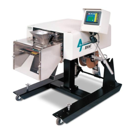
Chapter 1: Introduction Welcome Overview Standard Features System Integration Available Options Using this Manual - Typographical Conventions Contact Information Warranty Registration... - Page 8 With bag sizes that range from 4" x 3" to 11" x 16" and mil thickness from 1 mil to 4 mils, we hope the T-1000-S14 will meet all of your bagging needs. T-1000 Advanced Poly- Bagger™...
- Page 9 Set the quantity of finished bags to complete a work order or fill a shipping container. Once the work order is complete or the container is full, the T-1000-S14 stops to alert the operator to begin the next work order or to push aside the box and begin filling another. Pressing anywhere on the screen resets the counter and starts the bagging operation with minimum delay.
- Page 10 Dual Printing: Special programming allows the T-1000-S14 to operate with both the Next Bag Out printer and an offline printer in order to print on both sides of the bag. The offline printer is mounted...
- Page 11 E-Stop: This option can be used to stop the cycle operation of the T-1000-S14 and possibly other auxiliary infeed or outfeed equipment purchased with the T-1000-S14. FS-10 Flat Seal Assembly: Helps decrease/eliminate wrinkles in the seal by pulling the sides of the bag.
- Page 12 The conveyor fits perfectly underneath the T-1000-S14 and takes the product away. Small, lightweight and equipped with castors, use this conveyor anywhere in the plant. Designed for 24 hour / 7 days a week operation.
- Page 13 For general inquires: Sales@advancedpoly.com Or visit us online at www.advancedpoly.com In order to provide the best service possible, please have model and serial number ready.
-
Page 14: Warranty Registration
Warranty Registration This section must be completed and returned to Advanced Poly-Packaging, Inc. to register the T-1000 Bagger for Warranty Protection. Serial Number: (Serial Number located on the back panel) Company Name and Address Contact Name(s) / Title(s) / Phone Number... -
Page 15: Chapter 2: Safety, Getting Started
Chapter 2: Safety, Getting Started Chapter Summary Safety, Risks Installation Procedures Note on Adjustments to the T-1000-S14 Air and Power Requirements Assembly Instructions Air and Power Hookup Main Power Bag Threading Cycle Operation of the T-1000-S14 Quick Setup Procedures... - Page 16 Chapter Summary This chapter describes procedures to receive and set up the T-1000-S14, including uncrating instructions, environmental, air and power requirements, risks, required safety precautions, quick start procedures assembly instructions and height adjustments. Additionally, this chapter describes safety precautions, how to power on the T-1000-S14 and how to properly thread bags through the machine.
- Page 17 Installation Procedures The T-1000-S14 is transported as a single unit in a custom crate designed to protect the machine during shipment. It is shipped completely assembled except for a few items that are easily attached during installation.
- Page 18 Operating room temperature should range from 50°F to 100°F (10°C to 87.77°C). Note on Adjustments to the T-1000-S14 Upon receipt, it is not unusual for the T-1000-S14 to be out of alignment due to shipping and excessive handling. Unless physically damaged, the T-1000-S14 will function properly after minor adjustments are made.
- Page 19 The air supply should be fed to the T-1000-S14 with 3/8 ID flexible tubing. This tubing affixes to the coupler adapter (quick disconnect not provided). Connect the air to the regulator by holding the regulator firmly in one hand and pushing the airline connector on the male regulator connector.
- Page 20 Figure 2-1 Loosen for clockwise/counterclockwise adjustment and tilt adjustment Loosen for up/down adjustment Loosen for in/out adjustment...
- Page 21 Figure 2-2 CAUTION: Carefully loosen for up/down adjustment while two other people support the T-1000-S14. CAUTION: If the bagger is not held in position by two people, the weight of the machine may cause it to drop suddenly, causing severe injury.
- Page 22 Figure 2-3 Power Modem Switch Network DB25 Fuse Footswitch Main Power Switch Line Out Aux 3 Aux 1 Aux 2...
-
Page 23: Main Power
Main Power The main power switch is located on the side cover of the machine. See Figure 2-3. To turn the T-1000-S14 on, turn the switch counterclockwise from its vertical OFF position to its horizontal ON position. The green Power light on the touch screen will illuminate and the Introduction screen will be displayed. -
Page 24: Quick Setup Procedures
“nip” rollers. If a foot switch is not being used, press the Manual Cycle button. One bag should index, blow open and stop between the pressure bar and the heater bar. If the T-1000-S14 is not up to temperature, the machine will not cycle unless the RUN / SETUP button is toggled to SETUP. - Page 25 Threading Diagram, Standard Vertical, Single Dancer Figure 2-4...
- Page 26 Threading Diagram: Standard Vertical, Single Dancer, with Ti-1000 “Z” Printer Figure 2-5...
-
Page 27: Chapter 3: Touch Screen Operation
Chapter 3: Touch Screen Operation Touch Screen Operation Touch Screen Specifications / Features Touch Screen Program, Overview Introductory Screen Operation Screen Main Menu Settings Screen Options Menu Ti-1000 Inline Printer Counters Screen Continuous Strip Screen Technical Assistance & Troubleshooting Screens Bagger Auxiliary Options Pass Code Setup Screen Bagger Factory Settings... - Page 28 Introductory Screen When the T-1000 is turned on, an Introductory Screen is displayed. See Figure 3 - 1. The Introduction screen is a welcome screen, and it contains a button that will take the operator to the Operation screen. When turned on, the...
-
Page 29: Operation Screen
Operation Screen Operation Screen is provided to function with Pass Code Protection function of the machine. If the pass code function is enabled in the Technical Assistance Screen, the touch screen will default to the Operation Screen after a preset time has elapsed. -
Page 30: Fill Time
Fill Time The <Fill Time> button functions differently dependent upon the MODE in which the T-1000 is operating: MANUAL, AUTOMATIC (AUTO) mode or AUXILIARY mode. In the Manual mode with NO accumulating funnel, Fill Time will delay the operation from starting until this time has passed. -
Page 31: Reverse
226°C) depending on film thickness. Options Menu Options that have been added to the T-1000 at the factory can be setup from the Options Screen. If options were not installed at the factory, then N/A (Not available) will be displayed to the left of each options button. -
Page 32: Load Shelf
Use the <Setup> button to make it easier to mechanically adjust the fingers along the front plate slots on the T-1000. Once the mechanical adjustment is complete, press <ON> and <AUTO> for normal operation of the flat seal assembly. In the Auto mode, the option will operate automatically. -
Page 33: Compartment Seal
CS-10 Compartment Seal Seal the bag a second time to create a separate compartment in the bag. This option is useful to segregate different parts or protect damage caused from part contact. See Figure 3 - To start, set the First Seal Point by pressing the <Seal Point>... -
Page 34: Counting Funnel
CF-10 Counting Funnel This option is useful to automatically cycle the bagger when a preset number of parts have fallen through the funnel. See Figure 3 - 13. To turn ON the option, press the toggle button to ON. Press the <Reset> button to reset the count to the pre-set value. -
Page 35: Bag Opening Device
Blower During Loading toggle button turns off air if set to “OFF”. BO Cycle button allows you to test cycle the Bag Opening Device alone, without initiating other equipment or the T-1000 seal operation. LC-10 Light Curtain This option is used as a safety device to disable air power when the active area is obstructed. - Page 36 Screen” for more information. The Light Curtain option can be used as a means of initiating the cycle operation of the T-1000. To cycle the bagger automatically after the light curtain sensing area is cleared, press the <Mode> toggle button to change from Safe to Auto.
-
Page 37: Bag Open Detector
This hang-behind printer option is equipped with a festoon to collect bags that have already been printed on as they wait to go through the bagger. If this option is included on your machine, please refer to the Ti-1000Z / Ti- 1000RAP / T-1000-S14NBO Printer Manual for more details. AF-10 Accumulating Funnel... -
Page 38: Us-5000 / Us-5500 Semiautomatic Net Weigh Scale
<Blow-Off > indicates the time which a blower will remove the excess film from the bag. ES-10 E-Stop Circuit This option can be used to stop the cycle operation of the T-1000 and possibly other auxiliary infeed or out-feed equipment. One or more Estop buttons may be equipped. -
Page 39: Adjustable Stand Screen
Adjustable Stand Screen Operating height can be adjusted through the touch screen controlling a telescopic lift screw mechanism. To adjust the height, toggle the Option ON and press the UP Arrow or the DOWN Arrow. See Figure 3 - 24. DF-20 Part Diverter (Diverting Funnel) This feature is used to count bags and divert them from the... -
Page 40: Seal Validation
To cause a good seal and to confirm that each component required to obtain the seal is in range, we have added three validations to the T-1000: 1. Seal Temperature: a secondary controller was added with Figure 3 - 27 an alarm output that alarms when the temperature falls out of the set range in the temperature controller. -
Page 41: Medical Flat Seal
A Message will be displayed if any of the three validation components are out of range. The Pressure Sensor may also be added to the T-1000 to validate only pressure, without adding the other two components. For application requiring this validation only, the bagger will not operate unless the sensor provides an output indicated that the pressure is above a minimum allowable setting. -
Page 42: Uf-5000 Infeed Conveyor Operation Screen
If the bagger records “NO READ” after the rescan, the next bag is indexed with the same label printed a second time. If the T-1000-S14 is running in Manual Mode, a warning screen will be displayed, and the operator will have the option to reprint the label from that screen. -
Page 43: Ti-1000 Inline Printer
Ti-1000 Inline Printer The Thermal Inline Transfer Printer - prints text, graphics and bar codes, formatted in a separate software program. The label formats are "downloaded" to the printer from a To enable Printer operation on the Thermal Transfer (TT) Printer, press the highlighted <Printer Ti-1000>... -
Page 44: Temperature Calibration Screen
Temperature Calibration Screen This calibrated temperature screen will allow for temperature calibration of the heater bar. A typical temperature setting is 400°F or 204°C. The maximum temperature setting is 600°F or 260°C. The operator will have the option of choosing between two thermocouples (TC 1 and TC 2). Since variables such as position and age of the thermocouples may affect the actual reading, a calibrated readout will provide for more consistency in sealing. -
Page 45: Technical Assistance & Troubleshooting Screens
1001. See Figure 3 - 37. This code can and should be changed when the system is put into operation. See section 3.37 for “Pass Code Setup”. Several menu options are available from the Tech Assist. Menu which will assist with troubleshooting the T-1000- S14 and also change settings that affect the operation of the equipment. -
Page 46: Bagger Factory Settings
Pass codes prevent unauthorized individuals from tampering with settings. When equipment is shipped, APPI uses the following codes which should be changed prior to putting the T-1000 into operation. Factory Set Pass Codes: 1. Level 1 pass code: 1001 2. Level 2 pass code: 1002 To enable the pass code function, press the <Tech Assist>... - Page 47 TempRange: The temperature range above and below the Seal Temperature set point the heater bar must reach for the T-1000-S14 to operate fully. For example, if the Seal Temperature is set to 360°F(182.2°C) and the Temp Range is set to 10° , the temperature would be within the acceptable range if the heater bar temperature was between 350°F and 370°F (176.6°C and 187.7°C).
-
Page 48: Bag Registration
Air Pulse Delay: The amount of time, in seconds, before the air pulse operation begins. This delay setting allows the bag to get into position before blowing it open. To change this setting, press the <Air Pulse Delay> button, enter a value on the numeric keypad and press the <ENT> button. Brightness Control. -
Page 49: Job Save And Recipe Management
Job Save and Recipe Management From the Main Menu touch <Technical Assist> and enter the Level 1 Pass Code. Touch the <Bagger Factory> button to access the Bagger Factory screen. From there touch the <Bag Registration> button located along the right-hand side of the screen. -
Page 50: Internal Memory (Plc)
A. Internal Memory (PLC) Saving a job to Internal Memory: Select <PLC> in the Bag Registration screen (as described above) and exit to the Main Menu. Go to Settings and set the specifications for your job. Once the job is set, touch <Job Save> on the right side of the screen to access the Bagger Job Save screen, see Figure 3 - 43. -
Page 51: Memory Files And Data Structures
<Enter> to continue or <Exit> to cancel. Touching the QTY box will access a green numeric keypad where the operator can enter the number of products that will go into each bag. For instance, if three items go into the bag before it is sealed, the number 3 can be entered into that field. - Page 52 PLC Memory The Program File contains the system files, user-created instructions (Ladder Logic), and sub-routines. Contains the information required for operation of the Program File, organized by data type. Figure 3 - 49 External Storage The Memory Stick contains several types of data from the machine. The Bagger Settings are stored, similar to the information in PLC Storage.
- Page 53 BITMAP, CARD, DISP, FONT, HDCOPY, JPEG, LADDER, MEMO, MSG, OPELOG, SCRN, SNAP, SRAM, WAV, and WEBSERV are folders used by the touch screen software and will appear empty on the PC. This is because the files are hidden to prevent damage, and therefore do not show up in Windows Explorer. Do not store any information in these files as it will alter the program and will not function when the memory stick is re-inserted in the touch screen.
- Page 54 This data can be used to provide information about the machine, including number of parts per month. However, these files must be saved (copied) to a PC without the original file changed. Then, the files can be used and saved as MS Excel files for full use of the MS Excel formulas.
- Page 55 SMP0004.CSV Production Time Log – records the length of time the machine has been in production and gives details on the length of time the machine has been in the modes listed below. (See Figure 3 - 52) The data recorded in each column is as follows: A.
-
Page 56: Plc Info
Figure 3 - 53 Manual Backup: Data is recorded and saved automatically as described above. It can also be done manually using buttons on Log screens: • 'Write' - overwrite (save) the same file • 'Backup' - create new file (save as) •... -
Page 57: License Activation
License Activation The License Activation Screen controls access to Advanced Poly-Packaging’s proprietary software for controlling the T-1000 Bagger, and must be activated in order to operate the machine. When shipped from the factory, a 60-day trial activation is included. After full payment for the software is received, a full software license will be granted. -
Page 58: Production Graph And Temperature Graph
Production Graph and Temperature Graph Simple production and temperature graphs are provided to chart production and temperature throughout the day. See Figure 3 - 58 and Figure 3 - 59. Press the <Reset> button once to reset the production time and twice to reset the graph. Figure 3 - 58 Figure 3 - 59 Operation Mode Timers,... -
Page 59: Bagger Machine Info
Bagger Machine Info Model Number, Serial Number, Part Number and Line Number will be displayed; set at the factory. See Figure 3 - 62. Figure 3 - 62 Warning and Message Screens Normal operating message and fault messages will be displayed automatically to alert the operator of situations on the machine. - Page 60 Figure 3 - 68 Figure 3 - 67 Figure 3 - 69 Figure 3 - 70 Figure 3 - 71...
-
Page 61: Chapter 4: Adjustments Maintenance, Troubleshooting
Chapter 4: Adjustments Maintenance, Troubleshooting Machine Adjustments Compression (Nip) Roller Adjustment Dancer Assembly Adjustments (Roller Shaft) Dancer Bar and Brake Strap Adjustment Upper Roller Guides Teflon Adjustment Teflon Replacement Pressure Bar Adjustment Sealer Cylinders Adjustment Pressure Bar (Rubber) Replacement Anti-Jam Adjustment Heater Cartridge Replacement Replace Thermocouple Wire Preventative Maintenance and Scheduled Maintenance... - Page 62 Then "snug" the upper block bolts and recheck the alignment. Note: A light source (lamp) positioned to the rear of the T-1000-S14 showing light in the gap of the rollers will assist in judging whether the upper and lower roller are parallel.
- Page 63 LEFT SIDE PANEL COMPRESSION NIP ROLLER ADJUSTMENT Figure 4-1...
- Page 64 RIGHT SIDE PANEL COMPRESSION NIP ROLLER ADJUSTMENT Figure 4-2...
- Page 65 Upper Roller Guides Two plastic web guides are located on the upper rear roll of the T-1000-S14 and are used for fine adjustment of tracking. Once the web is tracking within +/- 1/8" (0.31 cm) left to right, the plastic web guides can be used to further assist with tracking.
- Page 66 LEFT SIDE PLATE TEFLON ADJUSTMENT Figure 4-3...
-
Page 67: Teflon Adjustment
Once the Teflon Sheet has reached the end of the roll, it is time for it to be replaced. To order a replacement Teflon Sheet, call APPI Service and refer to part number TP-300500, T-1000 Teflon Sheet. 1. Turn the power to the OFF position and unplug the power cord. Let machine cool for at least an hour. -
Page 68: Pressure Bar Adjustment
19. Slide the Front Gripper Plate back into position. 20. Place Front Plate Spacers behind Front Plate, insert button head screws, then tighten. Pressure Bar Adjustment The pressure bar, when actuated by the seal cylinder, is forced against the front plate. The pressure bar must be parallel to the front plate to avoid excessive wear of components. - Page 69 SEAL CYLINDER ADJUSTMENT Figure 4-4...
-
Page 70: Pressure Bar (Rubber) Replacement
PRESSURE BAR REPLACEMENT Figure 4-5... - Page 71 PRESSURE BAR REPLACEMENT Figure 4-6 Note: There is a 1/8"gap between the pressure rubber and front gripper plate.
-
Page 72: Anti-Jam Adjustment
Anti-Jam is working. Put the T-1000 in Auto Run and let it cycle. While it is running perform the Anti- Jam test again by placing a piece of 3/8 tubing doubled over and place in between Pressure Bar and Heat... - Page 73 ANTI-JAM OVERRIDE ADJUSTMENT Figure 4-7...
-
Page 74: Heater Cartridge Replacement
If the X4 LED is OFF when the rubber bar is not depressed into the nylon holder, the Coiled Cable, located inside the Main Frame of the T-1000-S14, must be tested and the two Acorn Nuts must be checked for wear. Check the cable for any cuts or worn spots that could be going to ground. If there are signs of wear and tear it must be replaced. - Page 75 HEATER BAR CARTRIDGE REPLACEMENT Figure 4-8 VIEW FROM UNDERNEATH THE INNER FRAME Note: Heater cartridge wires must make a sharp 90° bend at the end of heater bar. Wires should not extend past the end of the heater bar. Note: If the wires rub on the bagger when the heater bar is in or out, the heater cartridge will fall prematurely.
-
Page 76: Replace Thermocouple Wire
Replace the Teflon assembly ensuring the correct side is up, then reattach Gripper Plate. Preventative Maintenance and Scheduled Maintenance To extend the life of the T-1000-S14, qualified maintenance personnel must perform all required maintenance tasks. Failure to perform scheduled and preventative maintenance may cause excessive wear to components and will void the warranty. -
Page 77: Preventative Maintenance Checklist
Preventative Maintenance Checklist CHART ITEM DESCRIPTION PERIOD Filter / Air regulator Drain water from filter Air regulator Adjust pressure to 60 PSI Anti-jam device Check operation, adjust as needed (section 4.11) Pressure bar (rubber) Clean with alcohol Perforation sensor Clean sensor assembly with alcohol Upper (rubber) roller Inspect for nicks or cuts;... -
Page 78: Scheduled Maintenance Chart
Scheduled Maintenance Chart ITEM DESCRIPTION Drive belt Adjust/Inspect for wear (right panel) replace when necessary Heater element Inspect for fraying, cuts, and wiring loose connections Pressure bar Disassemble, clean, inspect assembly springs for wear, breakage (frequency dependent on environment and product) Guide rollers Inspect for free movement Roller bearings... -
Page 79: Spare Parts Kits
Fuse, 12 Amp, Time Delay TP-217116 Heater Cartridge TP-221416 Thermocouple Wire w/ Connector TP-300500-1 Teflon Sheet TP-306002 Seal Rubber Strip, T-1000 TP-404266 Poly Tubing,1/4" Dia. Blue (33M Roll) 10 ft. TP-404267 Poly Tubing,3/8"OD Dia. Blue (20M/Roll) 5 ft. TP-406181 Filter, 4 Micron (Air Knife) - Page 80 Transformer, Dual Voltage, 2400 Volts TP-214111 Battery for FP Sigma PLC TP-215000 Relay, Solid State 10A G-Series TP-501169-1 Driver, Vexta 5-Phase TP-403244 Cylinder, NCQ2A40-125-DUQ01760 T-1000 (Seal Cylinder) TP-T1MB00111 Rubber Strip Holder TP-403245 Cylinder, 25mm Bore X 10mm Stroke TP-T1MB00008 Heater Bar Mtg. Plate TP-T1MB00010...
-
Page 81: Troubleshooting Guide
The items included in this section cover the common causes of trouble that an operator might encounter during the operation of the T-1000-S14. When operating difficulties occur, the best procedure is to observe what is happening, identify the causes and effect the correction. Make only one adjustment at a time, checking the results of each adjustment. - Page 82 PROBLEM POSSIBLE CAUSE CORRECTIVE ACTION 1. Seal time too low 1. Increase in Settings screen 2. Heat (temperature) too low 2. Increase in Settings screen 3. Heater cartridge bad 3. Replace heater cartridge 4. Insufficient air pressure 4. Increase air pressure Pressure bar presses against 5.
-
Page 83: Plc Io Listing
PLC IO Listing Main PLC and Expansion PLC IO (Inputs and Outputs) listing is provided to assist in troubleshooting the T-1000-S14. Card: Address Description Normal State Inputs Main PLC Reserved for Stepper control Main PLC Perf Sensor Main PLC Not Used - Available... - Page 84 PLC Exp1 Light Curtain signal PLC Exp1 DF-20 Eye PLC Exp1 Barcode 'Quality Error' PLC Exp1 US50: Tray Home sensor PLC Exp1 US50: Tray Out sensor PLC Exp1 MV10 Temperature alarm PLC Exp1 MV10 Pressure alarm PLC Exp1 Barcode 'GOOD READ' PLC Exp1 BO-30 Bag Open sensor PLC Exp1...
- Page 85 Main PLC TIZ NBO Print request Main PLC Station #5 solenoid Main PLC H/V Armed (for 220V) Main PLC LC-10 Power relay Main PLC TIZ INL Print request Main PLC Auxiliary Out Main PLC Not Used - Not Available Main PLC Not Used - Not Available Main PLC Not Used - Not Available...
- Page 86 PLC Exp1 Not Used - Not Available PLC Exp1 Not Used - Not Available PLC Exp1 Not Used - Not Available PLC Exp1 Not Used - Not Available PLC Exp1 Not Used - Not Available PLC Exp1 Not Used - Not Available PLC Exp1 Not Used - Not Available PLC Exp1...
-
Page 87: Schematics
A circuit diagram of the 110V circuit is comprised of main power to the T-1000, through the fuse, Corcom filter, motor controller, solid state relay, heater element, line out, and into the power supply printed circuit board. - Page 88 110V Circuit T1kST-E1-110VAC...
- Page 89 Analog Card, Temperature Controller, Heater Circuit T1kST-E32_A21...
- Page 90 Stepper Motor Circuit T1kST-E4...
- Page 91 High Voltage Board Assembly...
- Page 92 Aux Interface T1kST-E7...
- Page 93 Solenoid Valve Circuit Diagram T1kST-E8...
- Page 94 PLC Expansion T1kST-E10_EXP-IO...
- Page 95 DB Connector Pin T1kST-E14_DBCon...
- Page 96 Panasonic Light Curtain T1kST-E34_LC_Panasonic SF4C...
- Page 97 Barcode Verifier T1kST-E35_BCV_Keyence SR...
-
Page 98: Pneumatic Piping Diagrams
APPI offers a piping diagram to assist in troubleshooting the T-1000 bagger. Piping from Solenoid Valve Stations 5 through 11 will change based on the configuration of the T-1000 and the options ordered by the customer. See Dwgs T- 1000 PNE 1 through 7. - Page 99 T-1000-S14 Pneumatic System Layout Diagram T-1000 PNE 1...
- Page 100 Printer Pneumatic Layout T-1000 PNE 2...
- Page 101 Accumulator Funnel Pneumatic Layout T-1000 PNE 3...
- Page 102 Load Shelf Pneumatic Layout T-1000 PNE 4...
- Page 103 Flat Seal Pneumatic Layout T-1000 PNE 5:...
- Page 104 Bag Opener Pneumatic Layout T-1000 PNE 6...
- Page 105 Trim Seal Pneumatic Layout T-1000 PNE 7...
- Page 106 This page intentionally left blank.
-
Page 107: Chapter 5: Parts And Drawings
Chapter 5: Parts and Drawings T-1000-S14 Advanced Poly-Bagger Base Assembly Upper Column Assembly Covers and Guarding Flat Load Shelf Assembly Dancer Assembly Touch Screen Assembly Main Frame Assembly Air Knife Assembly Sealer Frame Assembly: Drop Frame NBO Wide Sealer Frame Assembly: Drop Frame... - Page 108 T-1000-S14 Advanced Poly-Bagger T-T1000-S14 ITEM NO. QTY. PART NO DESCRIPTION TA-T10200 BASE ASSEMBLY TA-T10210 UPPER COLUMN ASSEMBLY TA-T10018 FLAT LOAD SHELF ASSEMBLY TA-T10220 DANCER ASSEMBLY TA-T10240 IOP (TOUCH SCREEN) SEE ASSEMBLY BAGGER W/OUT PRINTER TA-T10250-S14 MAIN FRAME ASSEMBLY TA-T10001-S14 AIR KNIFE ASSEMBLY...
- Page 109 VIEW FROM INSIDE BAGGER T-1000-S14 SYSTEM LAYOUT PN: T-T1000-S14...
- Page 110 Base Assembly PN: TA-T10200 ITEM QTY. PART NO DESCRIPTION TP- T1MA00051 LOWER BASE WELDMENT TP-T1MA00051-1 LOWER COLUMN TP-106094 STUD, FLOOR LEVELER TP-106119 SPRING PIN TP-109148 HAND KNOB TP- 110756 CASTER, SWIVEL TP-110763 CASTER, RIGID...
- Page 111 Upper Column Assembly PN: TA-T10210 ITEM QTY. PART NO DESCRIPTION TP-T1MC00019-1 BASE CLAMP (L.H.) TP-T1MC00019-2 BASE CLAMP (R.H.) TP-T1MC00019-3 BRACKET, MOUNTING TP-T1MA00087 CROSS PIPE TP-401267 ELBOW, DOUBLE UNIVERSAL TP-406260 FILTER/DRYER/REG. ASSEMBLY TP-401222 HEX NIPPLE...
- Page 112 Covers and Guarding PN: TA-T1-S14NOPRINT ITEM PART NO. DESCRIPTION TP-T1MD00004S14 ELECTRONICS COVER TP-T1MD00005S14 RIGHT SIDE COVER TP-T1MD00044 TOP COVER TP-111241 SNAP BUTTON PLUG TP-T1MO00226-4 LEXAN GUARD BRACKET (RIGHT) TP-T1MD00116-2 LEXAN GUARD 5.25" PASS THROUGH TP-T1MO00226-3 LEXAN GUARD BRACKET (LEFT)
- Page 113 Flat Load Shelf Assembly PN: TA-T10018 ITEM PART NO. DESCRIPTION TP-T1MB00074-2 LOAD SHELF BRACKET (RIGHT) TP-T1MB00074-1 LOAD SHELF BRACKET (LEFT) TP-T1MB00075 9" FIXED LOAD SHELF TP-T1MB00076 LOAD SHELF ROD...
- Page 114 Dancer Assembly PN: TA-T10220 ITEM NO. QTY. PART NO DESCRIPTION TP-T1MA00069-1 DANCER SIDE PLATE TP-C1MA00069-2 DANCER SIDE PLATE TA-T10011 DANCER GUIDE SUB-ASSEMBLY TP-T1MA00073 BAG ROLL SHAFT TP-504132 CAM FOLLOWER TP-T1MA00115 BELT TENSION STRAP & SPRING TP-104148 SPACER TP-101141 LOCKNUT, HEX #10-24 TP-T1MA00049 FILM TENSION HUB TP-103307...
- Page 115 Dancer Guide Subassembly PN: TA-T10011 ITEM NO. QTY. PART NO DESCRIPTION TP-T1MA00081 Dancer Tension Bar Cross Brace TP-109212 KNOB TP- T1MA00072 DANCER TENSION BAR TP-T1MA00186 TENSION ADJUSTER ASSEMBLY GUIDE ROLLER ASSEMBLY Guide Roller Assembly ITEM NO. QTY. PART NO DESCRIPTION TP-T1MA00089 DANCER GUIDE ROLLER TP-T1MA00090...
- Page 116 Dancer Guide Subassembly Guide Roller Assembly DANCER GUIDE SUBASSEMBLY PN: TA-T10011...
- Page 117 Touch Screen Assembly PN: TA-T10240 ITEM QTY. PART No DESCRIPTION TA-T10240-IOP SEVEN INCH TOUCH SCREEN TP-T1MD00109 MOUNTING BAR TP-111215 JOINING TEE TP-T1MD00094 BASE TELESCOPE TP-111104 COLLAR CLAMP TP-T1MA00088 BASE CLAMP PIPE...
- Page 118 Seven Inch Touch Screen TA-T10240IOP ITEM QTY. PART No DESCRIPTION TP-T1MD00040 TOUCH SCREEN HOUSING TP-T1MD00040-1 BACK COVER TP-111131 BALL GRIP POSITIONING ARM TP-111125-2 SOCKET ARM PART OF TP-220363 SCREEN STUD PART OF TP-220363 SCREEN CLIP TP-220364 TOUCH SCREEN TP-IOPBOLT-L MODIFIED BOLT TP-102147 Washer, 5/8 FLAT TP-101125...
- Page 119 SEVEN INCH TOUCH SCREEN PN: TA-T10240IOP...
- Page 120 GAUGE, .359 OD. TP-504101 BEARING TP-111010 SPRING CLOSURE COLLAR TP-501170 S14 STEPPER MOTOR TP-T14M1027 MOTOR PULLEY TP- T1MC00161 DRIVEN PULLEY TP-111142 CLAMP, COLLAR MAGNETIC SWITCH, T-1000 MACHINE OPEN TP-215200 SENSOR TP-T1MD00010-S14 PNEUMATICS BACK PANEL TA-T10002-S14 UPPER ROLLER ASSEMBLY TP-502104 BELT 210XL037...
- Page 121 MAIN FRAME ASSEMBLY PN: TA-T10250-S14...
- Page 122 Upper Roller Assembly PN: TA-T10002-S14 ITEM PART NO. DESCRIPTION TP-T1MC00119 FILM WEB ROLLER TP-T1MC00120 FILM WEB ROLLER SHAFT TP-107177 ¼ ID, 3/8 OD, 0.375 LONG BUSHING TP-T1MC00018-S14 ROLLER MOUNT TP-T1MC00118-1 FILM WEB ROLLER BRACKET LEFT TP-T1MC00118-2 FILM WEB ROLLER BRACKET RIGHT...
- Page 123 Air Knife Assembly PN: TA-T10001-S14 ITEM NO. PART NO. DESCRIPTION TP-BP-1013-S14 MOUNTING BAR TP-BP-1015-S14 AIR NOZZLE TP-T1MC00020NB FINGER PLATE TP-T1MC00125S14 SENSOR MOUNTING BAR TP-T1MC00083 HIGH VOLTAGE SENSOR INSULATOR TA-T100124-1 HIGH VOLTAGE SENSOR TP-405268 AIR KNIFE TP-401277 ELBOW, ¼ TUBE TP-401292 STRAIGHT, ¼...
- Page 125 Sealer Frame Assembly Drop Frame PN: TA-T10280-S14 ITEM NO. QTY. Part No DESCRIPTION TP-T1MB00200 SEALER FRAME NBO INTERNAL GUARD (4.25” PASS-THROUGH) TP-T1MD000276 NBO INTERNAL GUARD (5.25” PASS-THROUGH) TP- T1MD00276NB-1 NBO INTERNAL GUARD (6.25” PASS-THROUGH) TP-T1MD000276-2 NBO INTERNAL GUARD (7.25” PASS-THROUGH) TP-T1MD000276-3 BOTTOM INTERNAL GUARD (4.25”...
- Page 126 SHIELD MOUNTING ROD (4.25” Pass-Through) TP- T1MB00144-1 SHIELD MOUNTING ROD (5.25” Pass-Through) TP- T1MB00144-1 SHIELD MOUNTING ROD (6.25” Pass-Through) TP- T1MB00144-2 SHIELD MOUNTING ROD (7.25” Pass-Through) TP- T1MB00144-3 TP-104210 SPACER, 3/8LG,1/2 DIA.,.252 HOLE TP-T1MO00129 DROP FRAME FACE PLATE TP- T1MO00023 DROP FRAME SPACER TA-T10017 BAG FINGER GROUNDING ASSY...
- Page 127 Nut. *Note: If you purchased the T-1000-S14 with a Standard Frame instead of a Drop Frame, your part numbers for the Standard Sealer Frame Assembly are the same as those listed above with the exception of Item 30 TP-104210 Spacer, Item 31 TP-T1MO00129 Drop Frame Face Plate and Item 32 TP-T1MB00023 Drop Frame Spacer.
-
Page 128: Nbo Wide Seal Frame Assembly
5.13 NBO Wide Seal Frame Assembly PN: TA-T10280-S18NB ITEM NO. QTY. Part No DESCRIPTION TP-T1-00200S18 SEALER FRAME TP-T1MB00010-W18 SEALER ROD TIE BAR TP-T1MB00016-S18 SEAL CYLINDER MOUNTING BLOCK TP- T1MB00005-W18 FRONT GRIPPER PLATE SEAL GUIDE ROD (5.25” Pass Through) TP-T1MB00033-W18-1 SEAL GUIDE ROD (6.25” Pass Through) TP-T1MB00033-W18-2 SEAL GUIDE ROD (7.25”... - Page 129 TP-402186 FLOW CONTROL, #10-32 TP-211374 MAGNET, ROUND TP- T1MB00027-1 GRIPPER SPACER (W) TP-104210 SPACER, 3/8LG,1/2 DIA.,.252 HOLE TP- T1MD00275NB-S18-2 BOTTOM INTERNAL GUARD TP-107127-1 BRONZE BUSHING TP- T1MBO0129-W18 DROP FRAME FACE PLATE (WIDE) TP-107228 BUSHING, NYLON FLANGE TP- 107160-1 TEFLON COATED BUSHING TP-104124 SPACER TP-T1ME00209...
- Page 130 *Note: Items 5, 7, and 21 will vary depending upon the Pass-Through size of the Bagger. Please note this when ordering parts from the Bill of Materials shown above. For example, a Bagger with a 6.25” Pass-Through will use Seal Guide Rod TP-T1MB00033-W18-2, Shield Mounting Rod TP-T1MB00144-2, and Main Cylinder TP-403242.
-
Page 131: Pressure Bar Subassembly
A. Pressure Bar Subassembly PN: TA-T10005 ITEM NO. QTY. PART NO DESCRIPTION TP-T1MB00029 ANTI-JAM PRESSURE HOUSING TP-T1MB00030 ANTI-JAM CONTACT STRIP TP-T1MB00031 ANTI-JAM PRESSURE PAD TP-T1MB00068 ANTI-JAM CONTACT STRIP TP-T1MB00111 RUBBER STRIP HOLDER TP-306002 RUBBER SEAL TP-300001 RUBBER BUMPER TP-106093 1/4-20 x 2" STUD TP-108155 COMPRESSION SPRING TP-101130... -
Page 132: Heater Bar Subassembly
Heater Bar Subassembly PN: TA-T10006 ITEM NO. PART NO. DESCRIPTION TP-T1MB00008 HEATER BAR MOUNTING PLATE TP-T1MB00009-1 1/8" SEAL BAR* TP-T1MB00006 HEATER BAR CLAMP TP-T1MB00024 HEATER CARTRIDGE CORNER HANGER TP-T1MB00145 WIRE TIE DOWN TP-109096 HEATER CARTRIDGE WIRE LEAD CLAMP TP-104124 SPACER TP-217116 CARTRIDGE, HEATER TP-221416... -
Page 133: Teflon Guide Subassembly
Teflon Guide Subassembly PN: TA-T10009 ITEM PART NO. DESCRIPTION TP-T1MB00034 TEFLON FINGER TP-T1MB00040 TEFLON ROD TP-108089 EXTENSION SPRING TP-300500 TEFLON... -
Page 134: Grooved Roller Mounting Subassembly
Grooved Roller Mounting Subassembly PN: TA-T10012 ITEM PART NO. DESCRIPTION TP-T1MB00013 ALUMINUM ROLLER SHAFT TP-T1MB00004NB ROLLER MOUNTING BLOCK TP-T1MB00012 ROLLER TP-107227 BUSHING, THRUST NYLON TP-504107 BEARING, 0.500 BORE, 1.125 0D, 9/32 WIDE TP-T1MB00155 FILM WEB TENSION ROLL TP-T1MB00156 FILM WEB TENSION SHAFT TP-T1MC00121 REAR ROLLER CLIP TP-107163... -
Page 135: Bag Finger Grounding Subassembly
Bag Finger Grounding Subassembly PN: TA-T10017 ITEM PART NO. DESCRIPTION TA-T100124-3 GROUNDING SENSOR TP-T1MB00028 GROOVED METAL ROLLER FINGER TP-T1ME00325 GROUNDING SENSOR WIRE ASSEMBLY... -
Page 136: Latch Subassembly
Latch Subassembly PN: TA-T10019 ITEM PART NO. DESCRIPTION TP-T1MB00060 LATCH LOCK TP-T1MB00061 LATCH CAM TP-106135 DOWEL PIN... -
Page 137: Manifold Assembly
Manifold Assembly PN: TA-T10020-S14 ITEM PART NO. DESCRIPTION TP-T1MC00015S14 MANIFOLD BRACKET TP-402104 IN-LINE FLOW CONTROL, AS2051F-07 TA-T10025-S14 PNEUMATIC VALVE ASSEMBLY Note: Valves with one button (Single Valves) are part # TP-402266. Valves with two buttons (Dual Valves) are part # TP-402267. -
Page 138: Electrical Panel
25 PIN D-SUB FEMALE TP-218020 DIN RAIL TP-220511, TP-214111, PLC, BATTERY & COMM 2 CAS TP-220513 TP-220514 PLC, FPO-E32T-A Expansion I/O TP-T1MO00228 T-1000 EURO DISCONNECT SWITCH TP-T1MO00229 STANDOFF TP-212166 6 PIN MALE TP-212338 10 PIN FEMALE TP-220508 PLC ANALOG MODULE... - Page 139 ELECTRICAL PANEL PN: TA-T10270-S14...
-
Page 140: Bag Blow Off (Optional)
Bag Blow Off (Optional) TO-T1-BB10 ITEM NO. QTY. PART NO DESCRIPTION TP-TS10-106 TRIM SEAL BLOW-OFF TP- 404002 NOZZLE, SAFETY BLOW GUN TP-401258 MALE CONNECTOR... -
Page 141: Bag Deflator (Optional)
Bag Deflator (Optional) TO-T1-BF10-2 ITEM NO. QTY. PART NO DESCRIPTION TP-BF10-160 BACK PLATE TP-BF10-157 PLATE CLAMP HP-35027A1 SPONGE REPLACEMENT... -
Page 142: Notes
Notes Date Note...
Need help?
Do you have a question about the T-1000 and is the answer not in the manual?
Questions and answers