
Subscribe to Our Youtube Channel
Related Manuals for Advanced Poly-Packaging T-300


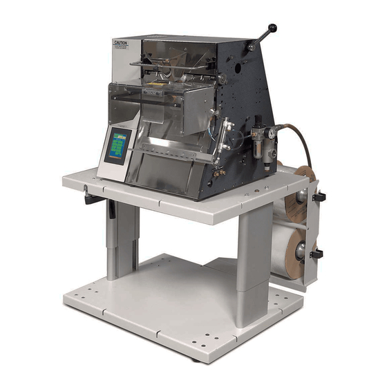
Summary of Contents for Advanced Poly-Packaging T-300
- Page 1 T-300 Table Top Bagger Operation Guide, Ver 1 Installation, Setup and Operation Guide...
- Page 2 Advanced Poly-Packaging, Inc. All information pertaining to the promotion, sale, distribution, operation, and maintenance of the T-300/375 Tabletop bagger / Bagger / Printer including this manual, drawings, schematic, wiring diagrams, video, brochures, specification sheets, figures, charts, or any other information, due to its proprietary design and manufacture remain the property of Advanced Poly Packaging, Inc.
-
Page 3: Table Of Contents
Contents ______________________________________________________________________________ Chapter 1, Introduction Welcome Overview Special Features System Integration Options Available Using This Manual Warranty Registration Chapter 2, Getting Started Installation Procedures Air & Power Requirements Assembly / Minor Adjustments Air & Power Hookup Main Power Bag Threading T-375 Ribbon Threading Cycle Operation Tension... - Page 4 Bill of Materials / Parts Dwgs Chapter 6, Preventive Maintenance & Scheduled Maintenance Preventive Maintenance & Schedule Maintenance P.M. Checklist Scheduled Maintenance Chart SP-10 T-300 Spare Parts Kit (Level 1) SP-10 T-375 Spare Parts Kit (Level 1) Chapter 7, Troubleshooting Troubleshooting Guide Troubleshooting Checklist...
-
Page 5: Chapter 1, Introduction
Chapter 1, Introduction __________________________________________________________________ Welcome Overview Special Features System Integration Options Available Using This Manual Warranty Registration... -
Page 6: Welcome
With a wide range of bag sizes (2" x 3" (standard frame only) to 11" x 16") and mil thickness (1 mil to 4 mil), we hope the T-300/T-375 will meet all of your bagging needs. -
Page 7: System Integration
The T-300 is specifically designed for hand loading. However, limited automatic operations may be available. 1.5 Available Options Although the T-300 is equipped with "built-in" options described above, various options can easily be added for special purpose packaging. The following options may be purchased from Advanced Poly-Packaging, Inc. -
Page 8: Warranty Registration
1.7 Warranty Registration (This section must be completed and returned to Advanced Poly Packaging, Inc. to register the T-300 for Warranty Protection) T-300 __________________________________________________________ (Serial Number located on the back panel) Company Name and Address Contact Names(s) / Title(s) / Phone Number... -
Page 9: Chapter 2, Getting Started
Chapter 2, Getting Started __________________________________________________________________ Installation Procedures Air and Power Requirements Assembly Instructions Height Adjustment Air & Power Hookup Bag Threading T-375 Ribbon Threading Cycle Operation Tension Note on Adjustments... -
Page 10: Installation Procedures
Then, transport the T-300 to the operating location using a cart. CAUTION: Do not attempt to lift the T-300 from the carton without first cutting all sides open. Also, to prevent injury, do not attempt to lift the machine without assistance. -
Page 11: Air & Power Hookup
The air supply should be fed to the T-300 with 3/8 ID flexible tubing; this tubing affixes to the coupler adapter (quick disconnect not provided). Connect the air to the regulator by holding the regulator firmly in one hand and pushing the air line connector on the male regulator connector. -
Page 12: Tension
Note: If bags were delivered with the T-300/T-375 or the size of the bags were known to APPI, the T-300/T-375 may be ready to run. Therefore, few changes to BAG SET UP may be required. 2.9 Increasing Tension To improve bag alignment, increased web tension may be required. You can increase tension by loosening one of the chucks that hold the roll in position on the shaft and pressing it inwards, toward the center of the roll of bags. -
Page 13: Chapter 3, Touch Screen Operation
Chapter 3, Touch Screen Operation ______________________________________________________________________________ Touch Screen Part Names Specifications Contrast Adjustment Touch Screen Program... - Page 14 3. Touch Screen Operation This section describes in detail, the identification, operation, and adjustments of the Touch Screen Program. 3.1 Touch Screen Part Names - Back Panel (See diagram 3.1.1) IOP Cable to Touch Screen / PLC Program Port PLC Wiring / Power Battery Cover / Battery Location DIP Switch Setting Caution: Do not attempt to reprogram the PLC or Touch Screen.
-
Page 15: Main Menu
3.4 Introductory Screen When the T-300 is turned on, an Introductory screen is displayed. See Fig. 3-1. The introductory screen is a welcome screen and has a button to take you to the Main Menu. When powered up, the machine will be in the Stop mode. - Page 16 To start the cycle operation immediately without a delay, change the setting to 0.00. Caution! To avoid personal injury, do not operate the T-300 AUTO mode when funnels or guards are removed. Funnels should not be removed unless a light curtain or palm buttons or other approved safety device is installed.
-
Page 17: Options Available Menu
3.11 Options Available Menu Options that can be added to the T-300 at the factory will be accessed from an Options Screen. If options were not installed at the factory, then N/A (Not available) will be displayed to the left of each options button. -
Page 18: Compartment Seal
Each time a setting is changed on the T-300/T-375, the settings are immediately saved in memory so that if power is lost, the T-300/T-375 will power on with the job that was running before power was lost. To Save a job to a memory location, first enter the Recipe (memory location), from 1 through 42 and enter your Part Number (up to 6 digits). -
Page 19: Auxiliary Screen
See Fig. 3-26. Pass codes prevent unauthorized individuals from tampering with settings. When equipment is shipped, APPI uses the following codes which should be changed prior to putting the T-300/T-375 into operation. Factory Set Pass Codes: 1. - Page 20 “factory code” so that the current pass codes can be displayed. This page intentionally left blank.
-
Page 21: Factory Settings: Default Settings
The PLC I/O screen is provided for maintenance personnel to determine the status of the PLC and review the mode of Outputs and Inputs. PLC I/O screen(s) are also used to assist APPI Service Technicians, working with your Maintenance Personnel to troubleshoot the T-300/T-375 in the field. See Figures 3-29 through 3-30. -
Page 22: Information / Message Screens
Step 5: (for the T-300 only) Press and hold the <Jog - > button until the perforation that was just centered on the heater bar reverses to the pinch roller fingers. Step 5: (for the T-375 only) Press and hold the <Jog - > button until the perforation is centered under the blue rubber roller but is still pinched between the rollers. -
Page 23: Chapter 4, Operation, Settings & Adjustments
Chapter 4, Settings & Adjustments ____________________________________________________ Machine Adjustments Component Replacement... -
Page 24: Machine Adjustments
Then "snug" the upper block bolts and recheck the alignment. Note (TIP): A light source (lamp) positioned to the rear of the T-300 / T-375 showing light in the gap of the rollers will assist in judging whether the upper and lower roller are parallel. -
Page 25: Idler Roller Guides
Step 2: Compression Adjustment With the rollers slightly touching and parallel, turn each adjustment coupler approximately 1/2 turn clockwise. Then test the compression by putting a bag between the rollers. Attempt to pull the bag between the rollers. If the bag pulls out easily, turn the compression adjustment coupler another 1/2 turn clockwise. -
Page 26: Pressure Bar Alignment / Cylinder Speed Adjustment
Inspect the springs for breaks or damage and replace as required. Inspect for debris and clean as required. Press the gripper plate inward evenly, then on one end, then the other, searching for the specific location causing the binding. Two blocks slide in a housing. Ensure that the blocks are not binding in the housing. -
Page 27: Rubber Strip Replacement
1. Remove air from the unit, turn the T-300 / T-375 power “OFF” and unplug the power cord. 2. Remove the worn rubber pad by pulling from the end corner of the rubber strip. Once started, the rubber will easily slide out from the metal pressure strip housing. -
Page 28: Heater Cartridge Replacement
4.11 Description of Antijam Circuit The antijam mechanism decreases the possibility of damage to the T-300 if product or other objects are in the seal area. The operation of the antijam circuit should be tested prior to production on a daily basis. - Page 29 If pushing the gripper plate in on either side fails to light its respective input, follow the following procedure. 1. Remove air from the unit, turn the T-300 power “OFF” and unplug the power cord and wait until the heater bar is fully cooled down.
-
Page 30: Print Head Replacement
Remove the front plate and PTFE Anti-Stick Sheet assembly. Remove the screws which hold the ring terminal and the jacketed wire clamp. Disconnect the connector and remove the wire. Reverse these steps to replace the wire. CAUTION: To avoid stretching or breaking the wire during heater cylinder extension, ensure that the wire is looped and free to bend during heater bar movement. -
Page 31: Chapter 5, Parts
Chapter 5, Parts __________________________________________________________________ Mechanical Drawings Parts Listing / Bill of Materials... -
Page 32: Chapter 6, Preventive Maintenance & Scheduled Maintenance
Chapter 6, Preventive Maintenance & Scheduled Maintenance ______________________________________________________________________________ PM Checklist Schedule Maintenance (CHART) -
Page 33: Preventive Maintenance & Schedule Maintenance
6.1 Preventive Maintenance & Scheduled Maintenance To extend the life of the T-300/T-375 qualified maintenance personnel must perform all required maintenance tasks. Failure to perform scheduled and preventive maintenance may cause excessive wear to components and will void the warranty. For the purpose of this manual, preventive maintenance (PM) tasks are considered periodic tasks which should be performed on a daily, weekly, or monthly basis. -
Page 34: Scheduled Maintenance Chart
6.3 Scheduled Maintenance Chart (perform every 500,000 cycles) CHART ITEM DESCRIPTION 2 3 4 6 7 8 9 10 Drive belt Adjust/Inspect for wear (left panel) replace when necessary Heater element Inspect for fraying, cuts, and wiring loose connections Pressure bar Clean, inspect for wear, Rubber strip replace if required... - Page 35 6.3 Preventive Maintenance (PM) Chart, Continued... ITEM DESCRIPTION 2 3 4 6 7 8 9 10 Inspected by: (Initials)
- Page 36 Chapter 7 ______________________________________________________________________________ Trouble Shooting...
-
Page 37: Troubleshooting Guide
The items included in this section cover the common causes of trouble which an operator might encounter during the operation of the T-300/T-375. When operating difficulties occur, the best procedure is to observe what is happening and attempt to isolate the problem. Make only one adjustment at a time, checking the results of each adjustment. - Page 38 1. Bag slipping through rollers 1. Clean upper and lower rollers with 2. Compression pressure alcohol to remove slip and dirt build-up Bag does not tear off insufficient 2. Adjust roller compression completely 3. Drive roller not reversing 3. Check tear off cylinder 4.
-
Page 39: 110V Circuit Dwg
Print Head. Wiring and descriptions of IO is described on this drawing. See Dwg T375-E6. 7.9 Touch Screen Circuit The T-300 / T-375 is equipped with a color touch screen. Wiring circuit is provided in this drawing. See Dwg T300-E7. -
Page 40: Plc Io Listing
7.11 PLC IO Listing Main PLC and Expansion PLC IO (Inputs and Outputs) Listing is provided to assist in troubleshooting the T-300 / T-375. Main PLC Input Description Output Description Stepper Control Stepper Motor Forward Bag Out Sensor Stepper Motor... - Page 41 7.12 Troubleshooting Notes / Technical Support Information Date Notes...
Need help?
Do you have a question about the T-300 and is the answer not in the manual?
Questions and answers