
Related Manuals for VIA Technologies 10GWG21Q00020


Summary of Contents for VIA Technologies 10GWG21Q00020
- Page 1 USER MANUAL SOM-9X20 Ultra-compact solution for graphics-intensive edge computing applications 1.05-05102018-175700...
- Page 2 VIA Technologies, Inc. reserves the right the make changes to the products described in this manual at any time without prior notice.
-
Page 3: Safety Precautions
Battery Recycling and Disposal • Only use the appropriate battery specified for this product. • Do not re-use, recharge, or reheat an old battery. • Do not attempt to force open the battery. • Do not discard used batteries with regular trash. •... -
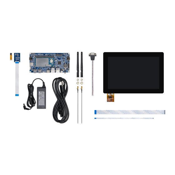
Page 4: Box Contents
• 1 x FPC cable for CSI connector Ordering Information Part Number Description 10GWG21Q00020 SOM module with Qualcomm Snapdragon 820E quad-core SoC, 64GB eMMC/UFS, 4GB POP LPDDR4 RAM, HDMI, 2 DSI, 3 CSI, USB 3.0, USB 2.0, UART, GPIO, SDIO, Wi-Fi + Bluetooth 4.1, GPS/GNSS, 2 PCIe 2.0 1-Lane... -
Page 5: Table Of Contents
SOM-9X20 User Manual Table of Contents 1. Product Overview ......................1 Key Features ............................1 1.2 Product Specifications ......................... 2 Layout Diagram ............................ 4 Product Dimensions ..........................5 2. Onboard I/O Connector ....................6 Wi-Fi & Bluetooth Micro-Miniature RF Antenna Connectors ............... 6 GPS Micro-Miniature RF Antenna Connector .................. - Page 6 SOM-9X20 User Manual List of Figures Figure 1: Layout diagram of the SOM-9X20 module (top side) ................4 Figure 2: Layout diagram of the SOM-9X20 module (bottom side) ..............4 Figure 3: Dimensions of the SOM-9X20 module ....................5 Figure 4: Dimensions of the SOMDB2 carrier board with SOM-9X20 module installed ........5 Figure 5: Wi-Fi &...
- Page 7 SOM-9X20 User Manual List of Tables Table 1: USB 2.0 ports pinouts ......................... 12 Table 2: JTAG connector pinouts ........................12 Table 3: Micro SD card slot pinouts ........................ 13 Table 4: MiniPCIe slot pinouts ......................... 15 Table 5: MXM 3.0 slot pinouts ......................... 20 Table 6: MIPI CSI connector pinouts .......................
-
Page 8: Product Overview
SOM-9X20 User Manual 1. Product Overview The highly-integrated VIA SOM-9X20 module is the first product offering from VIA powered by the Qualcomm® Snapdragon™ 820E quad-core processor that delivers the ideal balance of leading-edge performance and stunning visual and audio capabilities in a versatile and ultra-compact package for jump-starting the development of next-generation Enterprise IoT and embedded devices. Measuring a mere 82mm x 45mm, the VIA SOM-9X20 is a highly-integrated system-on-module powered by the Qualcomm® Snapdragon™ 820E quad-core processor which features the Qualcomm® Adreno™ 530 GPU that is designed to deliver immersive visual graphics. The VIA SOM-9X20 module also provides a full range of wireless connectivity features including GPS/GNSS, Wi-Fi, and Bluetooth through an integrated combo LGA module featuring three antenna connectors. -
Page 9: Product Specifications
SOM-9X20 User Manual Product Specifications Processor • Qualcomm Snapdragon 820E quad-core SoC ◦ Two high-performance Kryo cores up to 2.15GHz ◦ Two low power Kryo cores up to 1.593GHz System Memory • 4GB POP LPDDR4 SDRAM Storage • 64GB eMMC 5.1/UFS 2.0 Flash Memory • Micro SD card slot Graphics •... - Page 10 SOM-9X20 User Manual Supported I/O through MXM 3.0 connector • 1 x HDMI 2.0 port • 2 x MIPI DSI 4-Lane connectors • 3 x MIPI CSI 4-Lane connectors • 1 x USB 3.0 OTG • 1 x USB 2.0 host •...
-
Page 11: Layout Diagram
SOM-9X20 User Manual Layout Diagram GPS/GNSS receiver GPS micro-miniature RF antenna connector Snapdragon 820E Wi-Fi & BT 4.1 module quad-core SoC Wi-Fi/BT micro-miniature RF antenna connector Golden finger Wi-Fi micro-miniature RF antenna connector Figure 1: Layout diagram of the SOM-9X20 module (top side) eMMC Figure 2: Layout diagram of the SOM-9X20 module (bottom side) -
Page 12: Product Dimensions
SOM-9X20 User Manual Product Dimensions 82mm 75mm 3.5mm 3.5mm 45mm Figure 3: Dimensions of the SOM-9X20 module 170mm 3.5mm 86mm Figure 4: Dimensions of the SOMDB2 carrier board with SOM-9X20 module installed... -
Page 13: Onboard I/O Connector
SOM-9X20 User Manual 2. Onboard I/O Connector This chapter provides information about the SOM-9X20 ’s onboard I/O connector and its functionality. Wi-Fi & Bluetooth Micro-Miniature RF Antenna Connectors The SOM-9X20 comes with an onboard Wi-Fi + BT 4.1 combo LGA module that has Wi-Fi and Bluetooth micro- miniature RF antenna connectors which connect the Wi-Fi and Bluetooth antenna. The micro-miniature RF antenna connectors are labeled as "ANT1" (Wi-Fi/BT) and "ANT2" (Wi-Fi). ANT1 ANT2 Figure 5: Wi-Fi &... -
Page 14: Hardware Installation
SOM-9X20 User Manual 3. Hardware Installation This chapter provides information about the hardware installation procedures. Installing the SOM-9X20 Module on the SOMDB2 Carrier Board Step 1 Align the notch on the SOM-9X20 module with the counterpart on the MXM 3.0 slot on the SOMDB2 carrier board then insert the module at a 30° angle. Figure 7: Installing the SOM-9X20 module Step 2 Once the SOM-9X20 module has been fully inserted, push down the module until the standoff holes align with... -
Page 15: Connecting The Antenna Cable To The Wi-Fi & Bt Module
SOM-9X20 User Manual Connecting the Antenna Cable to the Onboard Wi-Fi & Bluetooth Module Step 1 Prepare the mating/unmating jig. We recommend to use a jig (as shown below) for connecting the plug connector on the antenna cable to the micro-miniature RF antenna connector on the onboard Wi-Fi & Bluetooth module. 40.00mm O 3.00mm 3.60mm MHF4L 90609-0001 1.90mm Top view 2.65mm 0.40mm Side view 2.00mm Figure 9: Recommended mating/unmating jig... -
Page 16: Software And Technical Support
SOM-9X20 User Manual 4. Software and Technical Support Android Support The SOM-9X20 features a complete software evaluation image featuring the Android 8.0 operating system. Linux Support The SOM-9X20 features a complete software evaluation image featuring the Linux Kernel 3.18.44 operating system. Technical Support and Assistance • For utilities downloads, latest documentation and new information about the SOM-9X20, please visit our website at https://www.viatech.com/en/boards/modules/som-9x20/ • For technical support and additional assistance, always contact your local sales representative or https://www.viatech.com/en/support/driver-support-fag/technical-support/ board distributor, or go to technical support. • For OEM clients and system integrators developing a product for long term production, other code and resources may also be made available. Please visit our website at https://www.viatech.com/en/ about/contact/ to submit a request. -
Page 17: Appendix A. Somdb2 Carrier Board Reference
SOM-9X20 User Manual Appendix A. SOMDB2 Carrier Board Reference A.1. Board Specification • RealTek RTL8111G Ethernet Controller • RealTek RTL8365MB LAN Hub Onboard I/O • 1 x MIPI DSI LCD panel connector • 1 x MIPI CSI Interface for camera module •... -
Page 18: Somdb2 Layout Diagram
SOM-9X20 User Manual A.2. SOMDB2 Layout Diagram Volume Down bu on miniPCIe Volume Up bu on Volume Up bu on USB 2.0 OTG switch MXM 3.0 USB 2.0 USB 2.0 RTC ba ery connector Micro SD card slot JTAG Figure 11: Layout diagram of the SOMDB2 carrier board (top side) (for light &... -
Page 19: Somdb2 Onboard I/O
SOM-9X20 User Manual A.3. SOMDB2 Onboard I/O A.3.1. USB 2.0 Port The SOMDB2 carrier board has two onboard USB 2.0 ports which feature a USB Type A receptacle connector and they are labeled as "USB2_R" and "USB2_L". The pinouts of the USB 2.0 ports are shown below. USB2_R Signal USB2_R... -
Page 20: Rtc Battery Connector
SOM-9X20 User Manual A.3.3. RTC Battery Connector The SOMDB2 carrier board is equipped with an onboard RTC battery connector used for connecting the external cable battery that provides power to the 32.768KHz crystal oscillator for Real Time Clock (RTC). The RTC battery connector is labeled as “RTC1”. RTC1 Figure 16: RTC battery connector diagram A.3.4. Micro SD Card Slot The SOMDB2 carrier board comes with a Micro SD card slot located on the front panel with support for a maximum storage capacity of 64GB. The pinouts of the Micro SD card slot are show below. Signal SD_DAT2 SD_DAT3... -
Page 21: Volume Button
SOM-9X20 User Manual A.3.5. Volume Button The SOMDB2 carrier board comes with two volume buttons which are used to control the volume. They are labeled as "VOL_UP" and "VOL_DOWN". The diagram of the volume buttons is shown below. VOL_UP VOL_DOWN Figure 18: Volume button diagram A.3.6. USB 2.0 OTG Switch The SOMDB2 carrier board comes with a USB 2.0 OTG switch labeled as "USB_ID_SET" which enables and disables the OTG function on the Micro USB 2.0 OTG port for Host mode/Device mode. The diagram of the USB 2.0 OTG switch is shown below. Enable Disable USB_ID_SET... -
Page 22: Minipcie Slot
SOM-9X20 User Manual A.3.7. MiniPCIe Slot The SOMDB2 carrier board is equipped with a miniPCIe slot which is labeled as “MPCIE”and is compatible with all PCIe 2.0 miniPCIe modules that are full length or half-length. The pinouts of the miniPCIe slot are shown below. MPCIE Figure 20: MiniPCIe slot diagram Signal Signal PCIE1_WAKE_N3V3_C VDD33_MPCIE VDD1V5 PCIE1_CLKREQ_N_3V3_C 10 N/A PCIE1_CLK_M 12 N/A PCIE1_CLK_P... -
Page 23: Mxm 3.0 Slot
SOM-9X20 User Manual A.3.8. MXM 3.0 Slot The SOMDB2 carrier board comes with a MXM 3.0 slot labeled as “MXM 3.0” which is an onboard slot for connecting the SOM-9X20 module. The MXM 3.0 slot is consists of 314-pins. The pinouts of the MXM 3.0 slot are shown below. E10-E19 E30-E39 E20-E29... - Page 24 SOM-9X20 User Manual Signal Signal PHONE_ON_N GPIO_57 VOL_UP_N GPIO_101 PM_GPIO_01 GPIO_102 PM_GPIO_03 GPIO_103 PM_PON_RESET_N GPIO_104 MSM_RESOUT_N GPIO_39 PM_GPIO_22 GPIO_92 GPIO_88 GPIO_93 GPIO_87 GPIO_94 GPIO_10 GPIO_96 GPIO_134 GPIO_99 GPIO_135 PM_GPIO_05 SSC_9 GPIO_8 SSC_8 GPIO_11 SSC_3 GPIO_127 SSC_2 GPIO_128 SSC_5 PM_GPIO_04 SSC_4 GPIO_84 SSC_6 BATT_THERM...
- Page 25 SOM-9X20 User Manual Signal Signal MIPI_DSI1_LANE1_P HDMI_TX0_P MIPI_DSI1_LANE1_M HDMI_TX0_M MIPI_DSI1_LANE2_P HDMI_TX1_P MIPI_DSI1_LANE2_M HDMI_TX1_M MIPI_DSI1_LANE3_P HDMI_TX2_P MIPI_DSI1_LANE3_M HDMI_TX2_M MIPI_CSI0_CLK_P MIPI_CSI1_CLK_P 100 MIPI_CSI0_CLK_M 101 MIPI_CSI1_CLK_M 102 GND 103 GND 104 MIPI_CSI0_LANE0_P 105 MIPI_CSI1_LANE0_P 106 MIPI_CSI0_LANE0_M 107 MIPI_CSI1_LANE0_M 108 GND 109 GND 110 MIPI_CSI0_LANE1_P 111 MIPI_CSI1_LANE1_P 112 MIPI_CSI0_LANE1_M 113 MIPI_CSI1_LANE1_M...
- Page 26 SOM-9X20 User Manual Signal Signal 167 PCIE2_TX_P 168 GND 169 PCIE2_TX_M 170 MIPI_CSI2_LANE3_P 171 GND 172 MIPI_CSI2_LANE3_M 173 PCIE2_RX_P 174 GND 175 PCIE2_RX_M 176 PCIE1_CLK_P 177 GND 178 PCIE1_CLK_M 179 USB3_SS_TX0_M 180 GND 181 USB3_SS_TX0_P 182 PCIE1_TX_P 183 GND 184 PCIE1_TX_M 185 USB3_SS_RX0_M 186 GND 187 USB3_SS_RX0_P...
-
Page 27: Table 5: Mxm 3.0 Slot Pinouts
SOM-9X20 User Manual Signal Signal 253 GPIO_125 254 GND 255 PM_GPIO_06 256 DIVCLK1_CDC 257 WLED_CABC 258 DIVCLK2_CDC 259 GPIO_40 260 GND 261 GPIO_63 262 SLIMBUS_CLK 263 GPIO_78 264 SLIMBUS_DATA0 265 GPIO_117 266 SLIMBUS_DATA1 267 GPIO_118 268 CODEC_RST_N 269 GPIO_119 270 SPKR_AMP_EN1 271 GPIO_120 272 SPKR_AMP_EN2 273 GPIO_121... -
Page 28: Mipi Csi Connector
SOM-9X20 User Manual A.3.9. MIPI CSI Connector The SOMSB2 carrier board has a MIPI CSI connector which is used to connect to a camera in order to support a wide range of imaging solutions. The connector is labeled as “CSI”. The pinouts of the MIPI CSI connector are shown below. Signal MIPI_CSI0_CLK_P MIPI_CSI0_CLK_M MIPI_CSI0_LANE2_M MIPI_DSI0_LANE2_P ON DIP 1 2 3 4 MIPI_CSI0_LANE1_P MIPI_CSI0_LANE1_M MIPI_CSI0_LANE0_P... -
Page 29: Mipi Dsi Lcd Connector
SOM-9X20 User Manual A.3.10. MIPI DSI LCD Connector The SOMDB2 carrier board provides a MIPI DSI LCD panel connector which is used for connecting LCD display. The MIPI DSI LCD panel connector is labeled as "DSI". The pinouts of the MIPI DSI LCD panel connector are shown below. Signal PANEL_VDD PANEL_VDD PANEL_LED_EN LED_PWM PANEL_EDID_SDA PANEL_EDID_SCL ON DIP PANEL_NC1 1 2 3 4 MIPI_DSI0_LANE2_P... -
Page 30: P-Cap Touch Connector
SOM-9X20 User Manual A.3.11. P-Cap Touch Connector The SOMDB2 carrier board comes with a P-Cap touch connector labeled as “TS” that is used to connect the touch controller. The pinouts of the P-cap touch panel connector are shown below. Signal HUB_USBDN_DM2_TOUCH HUB_USBDN_DP2_TOUCH ON DIP... -
Page 31: Com Connector
SOM-9X20 User Manual A.3.13. COM Connector The SOMBD2 carrier board is equipped with a COM connector that supports TX/RX for debugging. The pinouts of the COM connector are shown below. Signal ON DIP 1 2 3 4 RS232_TXD RS232_RXD Table 10: COM connector pinouts Figure 26: COM connector diagram A.3.14. -
Page 32: I 2 C Connector
SOM-9X20 User Manual A.3.15. I C Connector The SOMDB2 carrier board comes with two I²C connectors which are for connecting to the I²C devices, (for light & proximity sensor and NFC module). The pin headers are labeled as “NFC” and “PS1“. The pinouts of the pin headers are shown below. Signal NFC_VDD_IO VDD3V3 NFC_DWL_REQ_3V3 NFC_VEN_3V3 ON DIP 1 2 3 4 NFC_12C_SCL_3V3 NFC_12C_SDA_3V3 NFC_IRO_3V3... -
Page 33: Mic-In Connector
SOM-9X20 User Manual A.3.16. Mic-In Connector The SOMDB2 carrier board comes with a Mic-in connector for connecting a microphone. A cable must be used to connect the devices to the connector. The connector is labeled as “MIC”. The pinouts of the Mic-in connector are shown below. Signal MIC-IN Table 14: Mic-in connector pinouts ON DIP 1 2 3 4 Figure 30: Mic-in connector diagram A.3.17. -
Page 34: Audio Module Connector
SOM-9X20 User Manual A.3.18. Audio Module Connector The SOMDB2 carrier board comes with two audio module connectors for connecting the VT6093 audio module. The audio module connectors are labeled as "B2B_1" and "B2B_2". The pinouts of the audio module connectors are shown below. Signal Signal MIC_BIAS1 CDC_HPH_SW_L CDC_IN1_P CDC_HPH_SW_R CDC_IN1_M HPH_GND_SENSE MIC_BIAS2 CDC_DMIC_CLK0 B2B_2 B2B_1 CDC_IN2_P 10 CDC_DMIC_DATA0... -
Page 35: Boot Switch
SOM-9X20 User Manual A.3.19. Boot Switch The SOMDB2 carrier board comes with a boot switch which is used to select where the system will be booted from. The switch is labeled as “BOOT 1”. The settings of the boot switch are shown below. Setting eMMC Off Off Off Off Off Off On Off BOOT 1 Micro SD On Off On Off Table 18: Boot switch settings ON DIP... -
Page 36: Somdb2 External I/O
SOM-9X20 User Manual A.4. SOMDB2 External I/O A.4.1. HDMI Port ® The SOMDB2 carrier board has an HDMI port on the back panel which uses a HDMI port Type A receptacle connector to connect high definition video and digital audio using a single cable. The pinouts of the HDMI port are shown below. Signal Signal TX2+ CLK- TX2- Figure 34: HDMI port diagram TX1+ TX1-... -
Page 37: Micro Usb 2.0 Otg Port
SOM-9X20 User Manual A.4.3. Micro USB 2.0 OTG Port The SOMDB2 carrier board is equipped with a Micro USB 2.0 OTG port on the back panel which gives complete Plug and Play and hot swap capability for external devices. The USB interface complies with USB UHCI, Rev. 2.0. The pinouts of the USB 2.0 OTG port are shown below. -
Page 38: Power Button
SOM-9X20 User Manual A.4.5. Power Button The SOMDB2 carrier board comes with a power button on the back panel which allows the user to turn the system on and off. Figure 38: Power button diagram Power Button behavior Suspend/Resume System Quickly press the power button once to suspend. While in suspend mode quickly press once to resume. Pop-up power control menu Occurs when the power button is pressed for longer than 3 seconds. Restart Occurs when the power button is pressed for longer than 10 seconds. Table 23: Power button behavior description A.4.6. DC-In Jack The SOMDB2 carrier board comes with a DC-in jack that carries a 12V DC external power input. The specification and pinouts of the power DC-in jack are shown below. Signal VDD120_IN Figure 39: DC-in jack diagram Table 24: DC-in jack pinouts Physical Specification 6.0mm... -
Page 39: Somdb2 Dimensions
SOM-9X20 User Manual A.5. SOMDB2 Dimensions 170mm 3.5mm 86mm Figure 41: Dimensions of the SOMDB2 carrier board 147mm 127mm 110.16mm 91mm 71mm 49.88mm 33mm 19mm MAX 8.84mm 1.6mm MAX 6mm Figure 42: Dimensions of the SOMDB2 back panel I/O... -
Page 40: Appendix B. Somdb2 Mating Connector Vendors List
SOM-9X20 User Manual Appendix B. SOMDB2 Mating Connector Vendors List The following table lists the mating connector vendors for the SOMDB2 carrier board. Connector VIA P/N Vendor 99H30-071137 FOXCONN AS0B826-S55BB-7H 99H30-170982 ACES 50271-01401-001 USB2_OPT 99G30-170542 ACES 85204-0800L USB2_L/USB2_R 99G30-060962 CHUNFENG C023620-01 99G30-03304A1 PINREX 979-43-93480A 99G30-03305A1 PINREX 979-43-93080A 99G30-03306A1 PINREX 979-43-91580A 99G30-170252 ACES 50271-0060N-001 99G30-03307A1 PINREX... - Page 41 Taiwan Headquarters Japan China 1F, 531 Zhong-zheng Road, 940 Mission Court 3-15-7 Ebisu MT Bldg. 6F, Tsinghua Science Park Bldg. 7 Xindian Dist., New Taipei City 231 Fremont, CA 94539, Higashi, Shibuya-ku No. 1 Zongguancun East Road, Taiwan Tokyo 150-0011 Haidian Dist., Beijing, 100084 Japan China...
Need help?
Do you have a question about the 10GWG21Q00020 and is the answer not in the manual?
Questions and answers