Table of Contents
Advertisement
Quick Installation Guide
00825-0100-4664, Rev BB
January 2013
Rosemount 8712E Magnetic Flowmeter System
(Transmitter and Sensor)
www.rosemount.com
Step 1: Pre-Installation
Step 2: Handling
Step 3: Mounting
Step 4: Installation
(Flanged Sensors)
(Wafer Sensors)
(Sanitary Sensors)
Step 5: Grounding
Step 6: Wiring
Step 7: Basic Configuration
Product Certifications
End
Rosemount 8712 / 8700 Series
Start
Advertisement
Table of Contents

Subscribe to Our Youtube Channel
Related Manuals for Rosemount 8712E


Summary of Contents for Rosemount 8712E
- Page 1 Quick Installation Guide 00825-0100-4664, Rev BB Rosemount 8712 / 8700 Series January 2013 Rosemount 8712E Magnetic Flowmeter System (Transmitter and Sensor) Start Step 1: Pre-Installation Step 2: Handling Step 3: Mounting Step 4: Installation (Flanged Sensors) (Wafer Sensors) (Sanitary Sensors)
-
Page 2: Important Notice
Verify that the operating environment of the sensor and transmitter is consistent with the appropriate FM, CSA, ATEX, or IECEx approval. Do not connect a Rosemount 8712 to a non-Rosemount sensor that is located in an explosive atmosphere. WARNING The sensor liner is vulnerable to handling damage. -
Page 3: Step 1: Pre -Installation
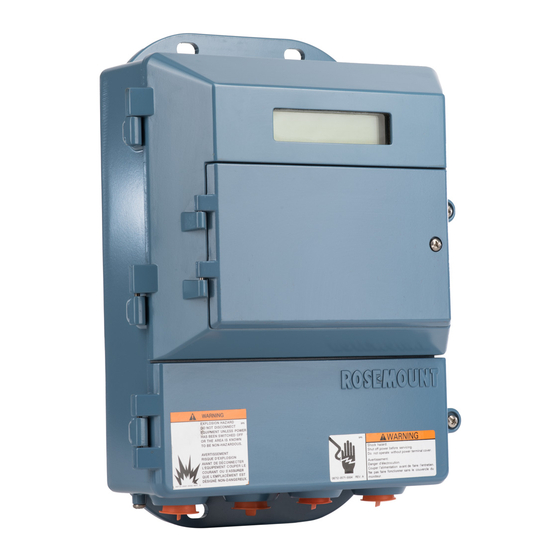
LOI screen (see Figure 1). The Rosemount 8712 is mounted separately from the sensor, it is not subject to limitations that might apply to the sensor. - Page 4 Quick Installation Guide 00825-0100-4664, Rev BB Rosemount 8712 / 8700 Series January 2013 Figure 1. Rosemount 8712 Dimensional Drawing WITH STANDARD COVER 9.01 (229) 4.31 0.44 2.81 3.11 (109) (11) (71) (79) 12.02 (305) 11.15 (283) 2.96 (75) WITH LOI COVER –14 NPT...
-
Page 5: Environmental Considerations
Remote mounted transmitters may be installed in the control room to protect the electronics from the harsh environment and provide easy access for configuration or service. Remotely mounted Rosemount 8712 transmitters require external power so there must be access to a suitable power source. - Page 6 Rosemount 8712 / 8700 Series January 2013 Electrical Considerations Before making any electrical connections to the Rosemount 8712, consider local and plant electrical standards and be sure to have the proper power supply, conduit, and other accessories necessary to comply with these standards.
- Page 7 Quick Installation Guide 00825-0100-4664, Rev BB Rosemount 8712 / 8700 Series January 2013 3: M OUNTING Upstream/Downstream Piping To ensure specification accuracy over widely varying process conditions, install the sensor a minimum of five straight pipe diameters upstream and two pipe diameters downstream from the electrode plane (see Figure 3).
- Page 8 3 and 9 o’clock positions, as shown on the right of Figure 4. The electrodes in the Rosemount 8711 are properly orientated when the top of the sensor is either vertical or horizontal, as shown in Figure 5. Avoid any mounting orientation that positions the top of the sensor at 45°...
-
Page 9: Flange Bolts
Quick Installation Guide 00825-0100-4664, Rev BB Rosemount 8712 / 8700 Series January 2013 4: I NSTALLATION Flanged Sensors Gaskets The sensor requires a gasket at each of its connections to adjacent devices or piping. The gasket material selected must be compatible with the process fluid and operating conditions. Metallic or spiral-wound gaskets can damage the liner. - Page 10 Sensors require a second tightening 24 hours after the initial installation. Over time, sensor liner materials may deform under pressure. Figure 7. Flange Bolt Torquing Sequence 8-bolt Table 1. Suggested Flange Bolt Torque Values for Rosemount 8705 and 8707 High-Signal Sensors PTFE/ETFE/PFA Polyurethane/Neoprene/Linatex/Adiprene liners...
- Page 11 Quick Installation Guide 00825-0100-4664, Rev BB Rosemount 8712 / 8700 Series January 2013 Table 2. Flange Bolt Torque and Bolt Load Specifications for 8705(EN 1092-1) PTFE/ETFE liner PN10 PN 16 PN 25 PN 40 Size (Newton- (Newton- (Newton- (Newton- Code Line Size...
- Page 12 Quick Installation Guide 00825-0100-4664, Rev BB Rosemount 8712 / 8700 Series January 2013 Table 2. (continued) (EN 1092-1) Flange Bolt Torque and Bolt Load Specifications for 8705 Polyurethane, Linatex, Adiprene and Neoprene Liners PN 10 PN 16 PN 25 PN 40...
- Page 13 O-ring Alignment 1. On 1.5 through 8-inch (40 through 200 mm) line sizes. Rosemount strongly recommends installing the alignment spacers provided to insure proper centering of the wafer sensor between the process flanges. Sensor sizes of 0.15, 0.30, 0.5 and 1 in. (4 through 25 mm), do not require alignment spacers.
- Page 14 Quick Installation Guide 00825-0100-4664, Rev BB Rosemount 8712 / 8700 Series January 2013 Table 4. Rosemount Alignment Spacer Table Rosemount Alignment Spacer Table Line Size Dash No. (in) (mm) Flange Rating 0A15 JIS 10K-20K 0A20 JIS 10K-20K 0A30 JIS 10K...
- Page 15 Gaskets are supplied between the IDF fitting and the process connection fitting, such as a Tri-Clamp fitting, on all Rosemount 8721 Sanitary sensors except when the process connection fittings are not supplied and the only connection type is an IDF fitting.
- Page 16 Quick Installation Guide 00825-0100-4664, Rev BB Rosemount 8712 / 8700 Series January 2013 5: G ROUNDING Use Table 6 to determine which process grounding option to follow for proper installation. The sensor case should be earth grounded in accordance with national and local electrical codes.
- Page 17 Quick Installation Guide 00825-0100-4664, Rev BB Rosemount 8712 / 8700 Series January 2013 Figure 12. Grounding with Grounding Rings or Lining Protectors Grounding Rings or Lining Protectors Figure 13. Grounding with Grounding Electrode...
- Page 18 Quick Installation Guide 00825-0100-4664, Rev BB Rosemount 8712 / 8700 Series January 2013 6: W IRING Conduit Ports and Connections This wiring section covers the connection between the transmitter and sensor, the 4-20 mA loop, and supplying power to the transmitter. Follow the conduit information, cable requirements, and disconnect requirements in the sections below.
-
Page 19: Transmitter To Sensor Wiring
AC or DC power wiring. • Device must be properly grounded or earthed according to local electric codes. • Rosemount combination cable part number 08732-0753-1003 (ft) or 08732-0753-2004 (m) is required to be used to meet EMC requirements. - Page 20 Quick Installation Guide 00825-0100-4664, Rev BB Rosemount 8712 / 8700 Series January 2013 CONTINUED To order cable specify length as quantity desired. 25 feet = Qty (25) 08732-0753-1003 Table 7. Cable Requirements Description Length Part Number Coil Drive Cable (14 AWG)
- Page 21 Figure 16. Remote Mount Wiring Diagrams NOTE When using the Rosemount supplied combination cable, the signal wires for terminals 18 and 19 contain an additional shield wire. These two shield wires should be tied with the main shield wire at terminal 17 at the sensor terminal block and cut back to the insulation in the transmitter junction box.
- Page 22 The user-selectable power supply switch is located on the electronics board. 8712E - connect negative (-)DC to Terminal 8 and positive (+)DC to Terminal 7. See Figure 18.
-
Page 23: Powering The Transmitter
January 2013 Powering the Transmitter The 8712E transmitter is designed to be powered by 90-250 Vac, 50–60 Hz or 12–42 Vdc. Before connecting power to the Rosemount 8712E consider the following standards and be sure to have the proper power supply, conduit, and other accessories. Wire the transmitter according to national, local and plant electrical requirements for the supply voltage. - Page 24 Units powered by 12-42 V DC powersupply may draw up to 1 amp of current. See Figure 20 for terminal block connections. Figure 20. 8712E Transmitter Power Connections Fuse AC Line or DC+ AC Neutral or DC–...
-
Page 25: Step 7: Basic Configuration
Quick Installation Guide 00825-0100-4664, Rev BB Rosemount 8712 / 8700 Series January 2013 Step 7: Basic Configuration Once the magnetic flowmeter is installed and power has been supplied, the transmitter must be configured through the basic setup. These parameters can be configured through either a local operator interface or a HART communication device. -
Page 26: Local Operator Interface
Local Operator Interface The optional Local Operator Interface (LOI) provides an operator communications center for the 8712E. By using the LOI, the operator can access any transmitter function for changing configuration parameter settings, checking totalized values, or other functions. The LOI is... -
Page 27: Product Certifications
RODUCT ERTIFICATIONS Approved Manufacturing Locations Rosemount Inc. — Eden Prairie, Minnesota, USA Fisher-Rosemount Technologias de Flujo, S.A. de C.V. — Chihuahua Mexico Emerson Process Management Flow — Ede, The Netherlands Asia Flow Technology Center — Nanjing, China European Directive Information The EC declaration of conformity can be found on page 31. - Page 28 Quick Installation Guide 00825-0100-4664, Rev BB Rosemount 8712 / 8700 Series January 2013 Canadian Standards Association (CSA) Non-incendive for Class I, Division 2 Groups A, B, C, and D non-flammable fluids (T4 at 40 °C) Dust-ignition proof Class II/III, Division 1 Groups E, F, and G (T4 at 40 °C)
- Page 29 Quick Installation Guide 00825-0100-4664, Rev BB Rosemount 8712 / 8700 Series January 2013 Sensor Approval Information Rosemount 8721 Rosemount 8705 Sensor Rosemount 8707 Sensor Rosemount 8711 Sensor Sensors Approval Non-flammable Flammable Non-flammable Flammable Non-flammable Flammable Non-flammable Codes Fluids Fluids Fluids...
- Page 30 Quick Installation Guide 00825-0100-4664, Rev BB Rosemount 8712 / 8700 Series January 2013 Table 12. Electrical Data Rosemount 8705 and 8711 Sensors Coil excitation circuit: 40 V DC (pulsed), 0,5 A, 20 W maximum Electrode circuit: in type of explosion protection intrinsic safety EEx ia IIC, U = 5 V, l = 0.2 mA,...
-
Page 31: Ec Declaration Of Conformity
No: RMD 1031 Rev. E Rosemount Inc. 12001 Technology Drive Eden Prairie, MN 55344-3695 declare under our sole responsibility that the product(s), Model 8712D and Model 8712E Magnetic Flowmeter Transmitters manufactured by, Rosemount Inc. 12001 Technology Drive 8200 Market Boulevard... - Page 32 ATEX Directive (94/9/EC) Model 8712D with Power Supply Option “03” and option code “N1” Model 8712E with Power Supply Option “2” and option code “N1” Baseefa05ATEX0170X – Type n Certificate Equipment Group II, Category 3 G (EEx nA nL IIC T4)
Need help?
Do you have a question about the 8712E and is the answer not in the manual?
Questions and answers