
Related Manuals for Rosemount 8800D Series


Summary of Contents for Rosemount 8800D Series
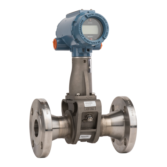
- Page 1 Reference Manual 00809-0100-4004, Rev BA August 2010 Rosemount 8800D Series Vortex Flowmeter www.emersonprocess.com/rosemount...
- Page 3 Read this manual before working with the product. For personal and system safety, and for optimum product performance, make sure you thoroughly understand the contents before installing, using, or maintaining this product. Within the United States, Rosemount Inc. has two toll-free assistance numbers: Customer Central Technical support, quoting, and order-related questions.
-
Page 5: Table Of Contents
Reference Manual 00809-0100-4004, Rev BA Rosemount 8800D August 2010 Table of Contents SECTION 1 How to Use this Manual........1-1 Safety Messages . - Page 6 Reference Manual 00809-0100-4004, Rev BA Rosemount 8800D August 2010 SECTION 3 Review ..........3-1 Process Variables .
- Page 7 Hazardous Location Certifications ......B-2 Rosemount 8800D with HART Protocol ..... B-2 North American Certifications.
- Page 8 Reference Manual 00809-0100-4004, Rev BA Rosemount 8800D August 2010 TOC-4...
-
Page 9: How To Use This Manual
Safety Messages ....... . . page 1-2 HOW TO USE This manual provides installation, configuration, troubleshooting, and other procedures for the use of the Rosemount 8800D Vortex Flowmeter. THIS MANUAL Specifications and other important information are also included. -
Page 10: Safety Messages
SYSTEM DESCRIPTION The Rosemount 8800D Vortex Flowmeter consists of a meter body and transmitter, and measures volumetric flow rate by detecting the vortices created by a fluid passing by the shedder bar. -
Page 11: Safety Messages
Vortex Flowmeter. Dimensional drawings for each Rosemount 8800D variation and mounting configuration are included in the Appendix on page A-20. The options available for the Rosemount 8800D flowmeter are also described in this section. The numbers in parentheses refer to the codes used to order each option. - Page 12 Reference Manual 00809-0100-4004, Rev BA Rosemount 8800D August 2010 Figure 2-1. Installation Flowchart Bench START HERE Commissioning FIELD INSTALL Review CONFIGURE Configuration Mount Flowmeter Configuration Process Config • Transmitter Mode • Process Fluid • Fixed Process Temp. Mount • Dens/Dens Ratio...
-
Page 13: Commissioning
To determine the correct flowmeter size for an application, process conditions must be within the stated requirements for Reynolds number and velocity. See Appendix A: Reference Data for sizing data. Contact your local Rosemount Inc. sales representative to obtain a copy of ® Instrument Toolkit which contains a sizing module for the Rosemount 8800D Vortex flowmeter. - Page 14 Reference Manual 00809-0100-4004, Rev BA Rosemount 8800D August 2010 High-Temperature Installations Install the meter body so the electronics are positioned to the side of the pipe or below the pipe as shown in Figure 2-2. Insulation may be required around the pipe to maintain an electronics temperature below 185 °F (85 °C).
-
Page 15: Wetted Material Selection
Wetted Material Ensure that the process fluid is compatible with the meter body wetted materials when specifying the Rosemount 8800D. Corrosion will shorten the Selection life of the meter body. Consult recognized sources of corrosion data or contact your Rosemount Sales Representative for more information. -
Page 16: Hardware Configuration
Rosemount 8800D August 2010 HARDWARE The hardware jumpers on the Rosemount 8800D enable you to set the alarm and security. (See Figure 2-5.) To access the jumpers, remove the electronics CONFIGURATION housing cover from the electronics end of the Rosemount 8800D. If your Rosemount 8800D includes an LCD option, the alarm and security jumpers are found on the face of the LCD indicator. -
Page 17: Failure Mode Vs. Saturation Output Values
Reference Manual 00809-0100-4004, Rev BA Rosemount 8800D August 2010 Failure Mode vs. The failure mode alarm output levels differ from the output values that occur when the operating flow is outside the range points. When the operating flow Saturation Output Values is outside the range points, the analog output continues to track the operating flow until reaching the saturation value listed below;... -
Page 18: Meter Body Installation Tasks
Gaskets The Rosemount 8800D requires gaskets supplied by the user. Be sure to select gasket material that is compatible with the process fluid and pressure ratings of the specific installation. -
Page 19: Wafer-Style Flowmeter Alignment And Mounting
Reference Manual 00809-0100-4004, Rev BA Rosemount 8800D August 2010 Table 2-3. Minimum Recommended Stud Bolt Lengths for Wafer Installation with ASME B16.5 (ANSI) Flanges Minimum Recommended Stud Bolt Lengths (in Inches) for Each Flange Rating Line Size Class 150 Class 300 Class 600 ½-inch... - Page 20 Spacers Spacers are available with the Rosemount 8800D to maintain the Rosemount 8800A dimensions. If a spacer is used, it should be downstream of the meter body. The spacer kit comes with an alignment ring for ease of installation. Gaskets should be placed on each side of the spacer.
- Page 21 Reference Manual 00809-0100-4004, Rev BA Rosemount 8800D August 2010 Figure 2-7. Wafer-Style Flowmeter Installation with Alignment Rings Spacer Alignment Ring (for Rosemount 8800D to maintain Rosemount 8800A dimensions) Alignment Rings Installation Studs and Nuts (Supplied by Customer) Flow Gaskets (Supplied by Customer) Figure 2-8.
-
Page 22: Flanged-Style Flowmeter Mounting
Reference Manual 00809-0100-4004, Rev BA Rosemount 8800D August 2010 Flanged-Style Physical mounting of a flanged-style flowmeter is similar to installing a typical section of pipe. Conventional tools, equipment, and accessories (such as Flowmeter Mounting bolts and gaskets) are required. Tighten the nuts following the sequence shown in Figure 2-9. -
Page 23: Flowmeter Grounding
Reference Manual 00809-0100-4004, Rev BA Rosemount 8800D August 2010 Figure 2-9. Flange Bolt Torquing Sequence 14 18 20-Bolt 8-Bolt 4-Bolt 16 1 12-Bolt 16-Bolt Flowmeter Grounding Grounding is not required in typical vortex applications; however, a proper ground will eliminate possible noise pickup by the electronics. Grounding straps may be used to ensure that the meter is grounded to the process piping. -
Page 24: Electronics Considerations
Reference Manual 00809-0100-4004, Rev BA Rosemount 8800D August 2010 ELECTRONICS Both integral and remote mounted electronics require input power at the electronics. For remote mount installations, mount the electronics CONSIDERATIONS against a flat surface or on a pipe that is up to two inches in diameter. -
Page 25: Cable Gland
Reference Manual 00809-0100-4004, Rev BA Rosemount 8800D August 2010 Figure 2-10. Proper Conduit Installation with Rosemount 8800D Conduit Line Conduit Line Cable Gland If you are using cable glands instead of conduit, follow the cable gland manufacturer’s instructions for preparation and make the connections in a conventional manner in accordance with local or plant electrical codes. - Page 26 24 mA. NOTE If a single power supply is used to power more than one Rosemount 8800D flowmeter, the power supply used and circuitry common to the flowmeters should not have more than 20 ohms of impedance at 1200 Hz.
- Page 27 Reference Manual 00809-0100-4004, Rev BA Rosemount 8800D August 2010 Figure 2-11. Power Supply Load Limitations 1500 1000 10.8 Power Supply (volts) = 41.7(V – 10.8) = power supply voltage (volts) = maximum loop resistance (ohms) Gage Number A.W.G. Ohms per 1,000 ft (305 m) at 68 °F (20 °C) Equivalent 2.525...
- Page 28 Reference Manual 00809-0100-4004, Rev BA Rosemount 8800D August 2010 Pulse Output NOTE Remember when using the pulse output, all power to the electronics is still supplied over the 4–20 mA signal wiring. The flowmeter provides an isolated transistor switch-closure frequency output signal proportional to flow, as shown in Figure 2-12.
- Page 29 Reference Manual 00809-0100-4004, Rev BA Rosemount 8800D August 2010 • If the flowmeter is protected by the optional transient protector, you must provide a high-current ground connection from the electronics housing to earth ground. Also, tighten the ground screw in the bottom center of the terminal block to provide a good ground connection.
-
Page 30: Remote Electronics
Reference Manual 00809-0100-4004, Rev BA Rosemount 8800D August 2010 Figure 2-15. 4–20 mA and Pulse Wiring with Electronic Totalizer/ Counter Pulse Counter 250 – Test Ammeter Remote Electronics If you order one of the remote electronics options (options R10, R20, R30, or... - Page 31 Reference Manual 00809-0100-4004, Rev BA Rosemount 8800D August 2010 Figure 2-16. Remote Electronics Installation ½ NPT Conduit Adapter or Cable Gland (Supplied by Customer) Electronics Housing Coaxial Cable Meter Adapter Union Washer Sensor Cable Nut Ground Connection Support Tube Housing...
-
Page 32: Calibration
Calibration Rosemount 8800D Flowmeters are wet-calibrated at the factory and need no further calibration during installation. The calibration factor (K-factor) is indicated on each meter body and is entered into the electronics. Verification can be accomplished with a Field Communicator or AMS. - Page 33 Reference Manual 00809-0100-4004, Rev BA Rosemount 8800D August 2010 The indicator features an eight-character (and five alphanumeric) liquid crystal display that gives a direct reading of the digital signal from the microprocessor. During normal operation, the display can be configured to...
-
Page 34: Installing The Indicator
Installing the Indicator For flowmeters ordered with the LCD indicator, the indicator is shipped installed. When purchased separately from the Rosemount 8800D, you must install the indicator using a small instrument screwdriver and the indicator kit (part number 8800-5640). The indicator kit includes: •... -
Page 35: Transient Protection
For flowmeters ordered with the transient protector option (T1), the protector is shipped installed. When purchased separately from the Rosemount 8800D, Transient Protector you must install the protector on a Rosemount 8800D flowmeter using a small instrument screwdriver, a pliers, and the transient protection kit (part number 8800-5106-3002 or 8800-5106-3004). - Page 36 Reference Manual 00809-0100-4004, Rev BA Rosemount 8800D August 2010 Figure 2-19. Transient Terminal Block Captive Screws Housing Ground Screw Transient Terminal Block Ground Tab 2-26...
-
Page 37: Review
The last step of start-up and commissioning is to check the flowmeter output to ensure that the flowmeter is operating properly. Rosemount 8800D digital process variables include: primary variable, primary variable as a percent of... -
Page 38: Pv% Of Range
Reference Manual 00809-0100-4004, Rev BA Rosemount 8800D August 2010 PV% of Range Percent of Range — The primary variable as a percentage of range provides a gauge as to where the current measurement of the meter is within Field Comm. - Page 39 They can be volumetric only. Configuration of a special unit involves entry of these values: base volume unit, base time unit, user defined unit and conversion number. Suppose you want the Rosemount 8800D to display flow in barrels per minute instead of gallons per minute, and one barrel is equal to 31.0 gallons.
- Page 40 1, 1, 4, 1, 3, 3 User Defined Unit is a format variable that provides a record of the flow units to which you are converting. The LCD on the Rosemount 8800D will display the actual units you define. The Field Communicator will simply display “SPCL.”...
- Page 41 Reference Manual 00809-0100-4004, Rev BA Rosemount 8800D August 2010 Mass Flow Units lb/s STon/min lb/min STon/h lb/h STon/d lb/d MetTon/min kg/s MetTon/h kg/min MetTon/d kg/h kg/d g/min NOTE If you select a Mass Units option, you must enter process density in your configuration.
- Page 42 Reference Manual 00809-0100-4004, Rev BA Rosemount 8800D August 2010 Start Field Comm. 1, 1, 4, 4, 2 Start — Starts the totalizer counting from its current value. Stop Field Comm. 1, 1, 4, 4, 3 Stop — Interrupts the totalizer count until it is restarted again. This feature is often used during pipe cleaning or other maintenance operations.
- Page 43 Reference Manual 00809-0100-4004, Rev BA Rosemount 8800D August 2010 Electronics Temperature Field Comm. 1, 1, 4, 7, 1 Displays the current electronics temperature value and units. Electronics Temperature Unit Field Comm. 1, 1, 4, 7, 2 Allows the user to select the units for electronics temperature from the available list.
- Page 44 Reference Manual 00809-0100-4004, Rev BA Rosemount 8800D August 2010 Process Temperature Units Field Comm. 1, 1, 4, 9, 2 Allows the user to configure the units for the process temperature from the available list. deg C deg F deg R...
-
Page 45: Basic Setup
00809-0100-4004, Rev BA Rosemount 8800D August 2010 BASIC SETUP The Rosemount 8800D must be configured for certain basic variables in order to be operational. In most cases, all of these variables are pre-configured at the Field Comm. 1, 3 factory. Configuration may be required if your Rosemount 8800D is not configured or if the configuration variables need revision. - Page 46 Configure the Density Ratio in one of two ways: Enter Density Ratio to convert from actual flow rate to standard flow rate. Enter the process and base conditions. (The Rosemount 8800D electronics will then calculate the density ratio for you). NOTE Be careful to calculate and enter the correct conversion factor.
-
Page 47: Reference K-Factor
= compressibility at standard (base) conditions (dimensionless) Example Configure the Rosemount 8800D to display flow in standard cubic feet per minute (SCFM). (Fluid is hydrogen flowing at conditions of 170 °F and 100 psia.) Assume base conditions of 59 °F and 14.696 psia.) 518.57 °Rx100 psiax1.0006... -
Page 48: Flange Type
Reference Manual 00809-0100-4004, Rev BA Rosemount 8800D August 2010 Flange Type Flange Type enables you to specify the type of flange on the flowmeter for later reference. This variable is preset at the factory but can be changed if Field Comm. -
Page 49: Mating Pipe Id (Inside Diameter)
Reference Manual 00809-0100-4004, Rev BA Rosemount 8800D August 2010 Mating Pipe ID The Pipe ID (Inside Diameter) of the pipe adjacent to the flowmeter can cause entrance effects that may alter flowmeter readings. You must specify (Inside Diameter) the exact inside diameter of the pipe to correct for these effects. Enter the Field Comm. -
Page 50: Range Values
Reference Manual 00809-0100-4004, Rev BA Rosemount 8800D August 2010 Range Values Range Values enables you to maximize resolution of analog output. The meter is most accurate when operated within the expected flow ranges for Field Comm. 1, 3, 8 your application. Setting the range to the limits of expected readings will maximize flowmeter performance. - Page 51 Reference Manual 00809-0100-4004, Rev BA Rosemount 8800D August 2010 Figure 3-1. Field Communicator Menu Tree for the Rosemount 8800D 1. Process 1. PV 1. Volumetric Flow 1. Volume Flow 1. Base Volume Unit 2. PV % Range 2. Mass Flow 2.
- Page 52 Minimum Span 1, 3, 8, 3 Num Req Preams 1, 4, 2, 3, 2 *Figure 3-1 and Table 3-2 are for Device Revision 1 and Device Revision 2 DD Revision 1 Rosemount 8800D Menu Tree and Fast Key codes 3-16...
- Page 53 Reference Manual 00809-0100-4004, Rev BA Rosemount 8800D August 2010 Table 3-3. Fast Keys for Rosemount 8800D Device Revision 2 DD Revision 3 Function Fast Key Function Fast Key Alarm Direction 1, 3, 1, 3, 2 Percent of Range 3, 4, 3, 2...
- Page 54 Reference Manual 00809-0100-4004, Rev BA Rosemount 8800D August 2010 3-18...
-
Page 55: Diagnostics/Service
This section contains information for advanced configuration parameters and diagnostics. The software configuration settings for the Rosemount 8800D can be accessed through a HART-based communicator or through a control system. The software functions for the Field Communicator are described in detail in this section of the manual. -
Page 56: Loop Test
Self Test Field Comm. 1, 2, 1, 5 Although the Rosemount 8800D performs continuous self-diagnostics, you can initiate an immediate diagnostic to check for possible electronics failure. Self Test checks proper communications with the transmitter and provides diagnostic capabilities for transmitter problems. Follow on-screen instructions if problems are detected, or check the appropriate appendix for error messages relating to your transmitter. - Page 57 Reference Manual 00809-0100-4004, Rev BA Rosemount 8800D August 2010 Shedding Frequency Field Comm. 1, 2, 4, 2 Shows the shedding frequency for the flow simulation. Configure Flow Simulation Field Comm. 1, 2, 4, 3 Allows you to configure your flow simulation (internal or external).
-
Page 58: D/A Trim
Volumetric Flow URV. This can be set by assigning Volumetric Flow to PV and setting range values. ADVANCED The Rosemount 8800D enables you to configure the flowmeter for a wider range of applications and special situations. These functions are grouped as FUNCTIONALITY... -
Page 59: Characterize Meter
August 2010 Characterize Meter The Meter Body variables provide configuration data that are unique to your Rosemount 8800D. The settings of these variables can affect the Field Comm. 1, 4, 1 compensated K-factor on which the primary variable is based. This data is provided during factory configuration and should not be changed unless the physical make-up of your Rosemount 8800D is changed. - Page 60 Reference Manual 00809-0100-4004, Rev BA Rosemount 8800D August 2010 Flange Type Field Comm. 1, 4, 1, 3 Flange Type enables you to specify the type of flange on the flowmeter for later reference. This variable is preset at the factory but can be changed if necessary.
-
Page 61: Configure Outputs
This value is entered as a percentage of the range of -1.5% to +1.5%. Configure Outputs The Rosemount 8800D is digitally adjusted at the factory using precision equipment to ensure accuracy. You should be able to install and operate the Field Comm. - Page 62 Follow the on-screen functions to complete the task. Alarm Level Select Field Comm. 1, 4, 2, 1, 5 Select the Alarm level of the transmitter. Either Rosemount standard or NAMUR compliant. Alarm / Sat Levels Field Comm. 1, 4, 2, 1, 6 Displays Alarm and Saturation mA output levels.
- Page 63 Field Comm. 1, 4, 2, 2, 1 The Rosemount 8800D comes with an optional pulse output option (P). This enables the flowmeter to output the pulse rate to an external control system, totalizer, or other device. If the flowmeter was ordered with the pulse mode option, it may be configured for either pulse scaling (based on rate or unit) or shedding frequency output.
- Page 64 Reference Manual 00809-0100-4004, Rev BA Rosemount 8800D August 2010 Direct (Shedding Frequency) Field Comm. 1, 4, 2, 2, 1, 2 This mode provides the vortex shedding frequency as output. In this mode, the software does not compensate the K-factor for effects such as thermal expansion or differing mating pipe inside diameters.
-
Page 65: Pulse Output Test
Reference Manual 00809-0100-4004, Rev BA Rosemount 8800D August 2010 For example: 1 pulse = 10 ft. Enter 10 for the distance. Scaled Mass Field Comm. 1, 4, 2, 2, 1, 5 This mode allows you to configure the pulse output based on a mass Flow Rate. - Page 66 Power Supply NOTE The Rosemount 8800D is set to poll address zero at the factory, allowing it to operate in the standard point-to-point manner with a 4–20 mA output signal. To activate multidrop communication, the transmitter poll address must be changed to a number between 1 and 15.
- Page 67 1, 4, 2, 3, 4 Burst Mode Configuration The Rosemount 8800D includes a burst mode function that broadcasts the primary variable or all dynamic variables approximately three to four times a second. The burst mode is a specialized function used in very specific applications.
- Page 68 Reference Manual 00809-0100-4004, Rev BA Rosemount 8800D August 2010 Burst Option Field Comm. 1, 4, 2, 3, 5 Burst Option enables you to select the variables to broadcast over the burst transmitter. Choose one of the following options: PV–Selects the process variable for broadcast over the burst transmitter.
-
Page 69: Signal Processing
August 2010 Local Display Field Comm. 1, 4, 2, 4 The Local Display function on the Rosemount 8800D allows you to select which variables are shown on the optional (M5) local display. Choose from the following variables: • Primary Variable •... - Page 70 Reference Manual 00809-0100-4004, Rev BA Rosemount 8800D August 2010 Optimize Flow Range Field Comm. 1, 4, 3, 1 The Optimize Flow Range function will automatically set the 8800D filter levels, Low Flow Cutoff (LFC), Trigger Level, and Low Pass Corner Frequency, to optimum settings based on the process density and process fluid type.
- Page 71 Reference Manual 00809-0100-4004, Rev BA Rosemount 8800D August 2010 Primary Variable (PV) Field Comm. 1, 4, 3, 2, 1 PV is the actual measured variable. On the bench, the PV value should be zero when the PV is mapped to a flow variable. Check the units on the PV to make sure they are configured correctly.
- Page 72 • Increase filtering • Increase sensitivity NOTE Do not adjust this parameter unless directed to do so by a Rosemount Technical Support Representative. Filter Restore Field Comm. 1, 4, 3, 3 Filter Restore enables you to return all of the signal conditioning variables to their default values.
-
Page 73: Device Information
Field Comm. 1, 4, 4, 1 Manufacturer is an informational variable provided by the factory. For the Rosemount 8800D, the Manufacturer is Rosemount. Field Comm. 1, 4, 4, 2 Tag is the quickest variable to identify and distinguish between flowmeters. - Page 74 Revisions Numbers are fixed informational variables that provide the revision number for different elements of your Field Communicator and Rosemount 8800D. These revision numbers may be required when calling the factory for support. Revision numbers can only be changed at the factory...
-
Page 75: Safety Messages
• Output with no actual flow. NOTE The Rosemount 8800D sensor is extremely reliable and should not have to be replaced. Please consult the factory before removing the sensor. SAFETY MESSAGES Instructions and procedures in this section may require special precautions to ensure the safety of the personnel performing the operations. -
Page 76: Troubleshooting Tables
The sensor cavity could contain line pressure if an abnormal failure has occurred inside the meter body. Depressurize flow line before removing the sensor nut. TROUBLESHOOTING The most common problems experienced by users of the Rosemount 8800D are listed in “Troubleshooting Tables” on page 5-2 along with potential causes TABLES of the problem and suggested corrective actions. -
Page 77: Advanced Troubleshooting
00809-0100-4004, Rev BA Rosemount 8800D August 2010 ADVANCED The Rosemount 8800D electronics provides several advanced troubleshooting features. These features enhance your ability to look inside TROUBLESHOOTING the electronics and can be helpful for troubleshooting inaccurate readings. As shown in Figure 5-1, there are several test points located on the electronics. - Page 78 Reference Manual 00809-0100-4004, Rev BA Rosemount 8800D August 2010 LOW FLOW CUTOFF OVERRANGE On start-up, the configured setting for the VDSP Low Flow Cutoff setting was found to be too high or too low. The increase range or decrease no flow noise command of the VDSP Low Flow Cutoff setting has not yet brought the setting into a valid range.
-
Page 79: Electronics Test Points
Reference Manual 00809-0100-4004, Rev BA Rosemount 8800D August 2010 Electronics Test Points As shown in Figure 5-1, there are several test points located on the electronics. Figure 5-1. Electronics Test Points Test Freq IN GROUND The electronics is capable of internally generating a flow signal that may be used to simulate a sensor signal to perform electronics verification with a Handheld Communicator or AMS interface. -
Page 80: Tp1
Reference Manual 00809-0100-4004, Rev BA Rosemount 8800D August 2010 TP1 is the vortex shedding signal after it has gone through the charge amplifier and low pass filter stages and into the input of the sigma delta A-to-D converter ASIC in the electronics. -
Page 81: Diagnostic Messages On Lcd
Reference Manual 00809-0100-4004, Rev BA Rosemount 8800D August 2010 Figure 5-5. Improper Sizing/Filtering Trigger Level Vortex Signal (TP1) Shedding 3.0 V Frequency Output DIAGNOSTIC In addition to the output, the LCD indicator displays diagnostic messages for troubleshooting the flowmeter. These messages are as follows:... - Page 82 Reference Manual 00809-0100-4004, Rev BA Rosemount 8800D August 2010 FAULT_BDREV The flowmeter electronics has detected incompatible electronics hardware. Contact your Field Service Center. FAULT_LOOPV The flowmeter electronics has detected insufficient voltage to power the sensor board. Most likely the cause is low voltage at transmitter 4–20 mA terminals.
-
Page 83: Testing Procedures
4-1 for details. HARDWARE The following procedures will help you disassemble and assemble the Rosemount 8800D hardware if you have followed the troubleshooting guide REPLACEMENT earlier in this section of the manual and determined that hardware components need to be replaced. -
Page 84: Replacing The Electronics Boards
(Option T1). Screw on and tighten the cover. Replacing the The Rosemount 8800D electronics boards may need to be replaced if they have been damaged or otherwise become dysfunctional. Use the following Electronics Boards procedures to replace electronics boards in the Rosemount 8800D. You will need a small Phillips head screwdriver and pliers. - Page 85 Rosemount 8800D August 2010 Remove the Electronics Boards Turn off the power to the Rosemount 8800D. Unscrew and remove the electronics board compartment cover. (Unscrew and remove the LCD cover if you have the LCD option). Figure 5-7. Electronics Boards Assembly Electronics Boards If the meter has the LCD indicator option, loosen the two screws.
-
Page 86: Replacing The Electronics Housing
Tighten the two screws that retain the LCD indicator. e. Insert the alarm and security jumpers in the correct location. Replace the electronics board compartment cover. Replacing the The Rosemount 8800D electronics housing can be replaced easily when necessary. Use the following procedure: Electronics Housing Tools Needed •... -
Page 87: Replacing The Sensor
10. Apply power. Replacing the Sensor The sensor for the Rosemount 8800D is a sensitive instrument that should not be removed unless there is a problem with it. If you must replace the sensor, follow these procedures closely. Please consult the factory before removing the sensor. -
Page 88: Replacing The Sensor: Removable Support Tube
If there is process fluid in the sensor cavity, immediately re-tighten the valve nut until process fluid stops venting. Do NOT tighten any further. STOP and contact your Rosemount Sales Representative. The meter body may need to be replaced. - Page 89 Reference Manual 00809-0100-4004, Rev BA Rosemount 8800D August 2010 Removable Support Tube Loosen the four support tube anchor bolts with a -in. open end wrench. (See “”Removable Support Tube Assembly” Figure 5-8) Figure 5-8. Removable Support Tube Assembly Anchor Bolts...
- Page 90 Reference Manual 00809-0100-4004, Rev BA Rosemount 8800D August 2010 NOTE Do not scratch or deform any part of the sensor, sensor cavity, or sensor nut threads. Carefully brush the sealing surface clean with a soft bristle brush. Moisten a cotton swab with an appropriate cleaning liquid.
- Page 91 Reference Manual 00809-0100-4004, Rev BA Rosemount 8800D August 2010 Figure 5-10. Sensor Installation – Improper Alignment Improper Alignment (before seating) Top View Sensor of Flowmeter Sensor cavity in flowmeter Sensor centerline is not aligned with flowmeter centerline. Damage to sensor will occur.
-
Page 92: Remote Electronics Procedure
Install the flowmeter electronics housing. See Replacing the Electronics Housing on page 5-12. Remote Electronics If the Rosemount 8800D electronics housing is mounted remotely, some replacement procedures are different than for the flowmeter with integral Procedure electronics. The following procedures are exactly the same: •... - Page 93 Reference Manual 00809-0100-4004, Rev BA Rosemount 8800D August 2010 NOTE Do not pull the adapter more than 1.5-in. (40 mm) from the top of the support tube. Damage to the sensor may occur if the sensor cable is stressed. Figure 5-13. Coaxial Cable Connections ½...
-
Page 94: Coaxial Cable At The Electronics Housing
Reference Manual 00809-0100-4004, Rev BA Rosemount 8800D August 2010 Attach the Meter Adapter If you are using a conduit adapter or cable gland, slide it over the plain end of the coaxial cable (the end without a ground wire). Slide the meter adapter over the coaxial cable end. - Page 95 Reference Manual 00809-0100-4004, Rev BA Rosemount 8800D August 2010 Figure 5-14. Remote Electronics Exploded View Electronics Housing Ground Connection Housing Coaxial Base Screw Cable Nut Housing Adapter Housing Adapter Screws Conduit Adapter (optional - supplied by customer) Loosen the conduit adapter (or cable gland) from the housing adapter.
-
Page 96: Changing The Housing Orientation
Use the following procedure for replacement. Replacement (MTA Option Only) NOTE Disconnect power before replacing temperature sensor. Turn off power to Rosemount 8800D. Remove temperature sensor from meter body by using a -in. open end wrench. NOTE Use plant approved procedure for removing a temperature sensor from a thermowell. -
Page 97: Return Of Material
Reapply power to Rosemount 8800D. RETURN OF MATERIAL To expedite the return process, call the Rosemount North American Response Center at 800-654-RSMT (7768) toll-free number. This center, available 24 hours a day, will assist you with any needed information or materials. - Page 98 Reference Manual 00809-0100-4004, Rev BA Rosemount 8800D August 2010 5-24...
-
Page 99: Specifications
Ordering Information ......page A-34 SPECIFICATIONS The following specifications are for the Rosemount 8800D, Rosemount 8800DR, and Rosemount 8800DD, except where noted. Information is included in this section for both HART and ™... - Page 100 Reference Manual Rosemount 8800D 00809-0100-4004, Rev BA August 2010 NOTE Consult your local sales representative to obtain a computer sizing program that describes in greater detail how to specify the correct flowmeter size for an application. The Reynolds number equation shown below combines the effects of density ( ), viscosity ( pipe inside diameter (D), and flow velocity (V).
- Page 101 Reference Manual Rosemount 8800D 00809-0100-4004, Rev BA August 2010 Process Temperature Limits Standard –40 to 450 °F (–40 to 232 °C) Extended –330 to 800 °F (–200 to 427 °C) MultiVariable (MTA option) –50 to 800 °F (–40 to 427 °C) •...
- Page 102 Reference Manual Rosemount 8800D 00809-0100-4004, Rev BA August 2010 Weld-End Style Meter W1 Welds to Schedule 10 mating pipe Max Working Pressure 720 psig (4.96 MPa-g) W4 Welds to Schedule 40 mating pipe Max Working Pressure 1440 psig (9.93 MPa-g) W8 Welds to Schedule 80 mating pipe Max Working Pressure 2160 psig (14.9 MPa-g)
- Page 103 Permanent Pressure Loss The approximate permanent pressure loss (PPL) from the Rosemount 8800D flowmeter is calculated for each application in the Vortex sizing software available from your local Rosemount representative. The PPL is determined using the equation: A f ...
- Page 104 Reference Manual Rosemount 8800D 00809-0100-4004, Rev BA August 2010 Minimum Upstream Pressure (Liquids) Flow metering conditions that would allow cavitation, the release of vapor from a liquid, should be avoided. This flow condition can be avoided by remaining within the proper flow range of the meter and by following appropriate system design.
- Page 105 Reference Manual Rosemount 8800D 00809-0100-4004, Rev BA August 2010 Transient Protection The optional transient terminal block prevents damage to the flowmeter from transients induced by lightning, welding, heavy electrical equipment, or switch gears. The transient protection electronics are located in the terminal block.
- Page 106 Reference Manual Rosemount 8800D 00809-0100-4004, Rev BA August 2010 Virtual Communications Relationships (VCRs) (F fieldbus only) OUNDATION Two (2) predefined (F6, F7) Four (4) configured (see Table A-5) Table A-5. Block Information Execution Time Block Base Index (Milliseconds) Resource (RB) —...
- Page 107 *Conditions: 77 °F (25 °C) and 14.7 psia (1.01 bar absolute) (1) Table A-7 is a reference of flow rates that can be measured for the standard Rosemount 8800D and the reducer 8800DR Vortex Meters. It does not consider density limitations, as described in Table A-2 and Table A-5.
- Page 108 Reference Manual Rosemount 8800D 00809-0100-4004, Rev BA August 2010 Table A-8. Air Flow Rate Limits at 59 °F (15 °C) Minimum and Maximum Air Flow Rates for line sizes inch/DN 15 through 1 inch/DN 25 Inch/DN 15 1 Inch/DN 25...
- Page 109 Reference Manual Rosemount 8800D 00809-0100-4004, Rev BA August 2010 Table A-10. Air Flow Rate Limits at 59 °F (15 °C) Minimum and Maximum Air Flow Rates for line sizes 3 inch/DN 80 through 4 inch/DN 100 3 Inch/DN 80 4 Inch/DN 100...
- Page 110 306.3 213.6 NOTES The Rosemount 8800D measures the volumetric flow under operating conditions (i.e. the actual volume at the operating pressure and temperature– acfm or acmh), as shown above. However, gas volumes are strongly dependent on pressure and temperature. Therefore, gas quantities are typically stated in standard or normal conditions (e.g.
- Page 111 Reference Manual Rosemount 8800D 00809-0100-4004, Rev BA August 2010 Table A-13. Saturated Steam Flow Rate Limits (Assumes Steam Quality is 100%) Minimum and Maximum Saturated Steam Flow Rates for line sizes inch/DN 15 through 1 inch/DN 25 ½ Inch/DN 15...
- Page 112 Reference Manual Rosemount 8800D 00809-0100-4004, Rev BA August 2010 Table A-15. Saturated Steam Flow Rate Limits (Assumes Steam Quality is 100%) Minimum and Maximum Saturated Steam Flow Rates for line sizes 3 inch/DN 80 through 4 inch/DN 100 3 Inch/DN 80...
-
Page 113: Performance Specifications
9025 4094 20404 9255 14226 6453 PERFORMANCE The following performance specifications are for all Rosemount models except where noted. Digital performance specifications applicable to both SPECIFICATIONS Digital HART and F fieldbus output. OUNDATION Flow Accuracy Includes linearity, hysteresis, and repeatability. - Page 114 Reference Manual Rosemount 8800D 00809-0100-4004, Rev BA August 2010 Process Temperature Accuracy 2.2° F (1.2° C) or 0.4% of reading (in °C), whichever is greater. Mass Flow Accuracy for Temperature Compensated Mass Flow 2.0% of rate (Typical) Repeatability ± 0.1% of actual flow rate Stability ±0.1% of rate over one year...
-
Page 115: Physical Specifications
Reference Manual Rosemount 8800D 00809-0100-4004, Rev BA August 2010 Mounting Position Effect Meter will meet accuracy specifications when mounted in horizontal, vertical, or inclined pipelines. Best practice for mounting in a horizontal pipe is to orient the shedder bar in the horizontal plane. - Page 116 Reference Manual Rosemount 8800D 00809-0100-4004, Rev BA August 2010 Electrical Connections –14 NPT or M20 X 1.5 conduit threads; screw terminals provided for 4–20 mA. F OUNDATION fieldbus and pulse output connections; communicator connections permanently fixed to terminal block. Non-Wetted Materials...
- Page 117 The electronics must not exceed 185°F (85°C). The following is for reference, please note that the pipe was insulated with 3 inches of ceramic fiber insulator. Figure A-1. Rosemount 8800 Vortex Flowmeter Ambient/process temperature limits Shows Combinations of Ambient and Process Temperatures Needed to Remain at or Below 185°F (85°C) Housing...
-
Page 118: Dimensional Drawings
Reference Manual Rosemount 8800D 00809-0100-4004, Rev BA August 2010 DIMENSIONAL DRAWINGS Figure A-2. Flanged-Style Flowmeter Dimensional Drawings ( -through 12-in./15 through 300 mm Line Sizes) Terminal Cover 3.20 (81) 2.56 2.85 (65) (72) 1.10 (28) Diameter 3.06 (78) 1.00 (25.4) - Page 119 Reference Manual Rosemount 8800D 00809-0100-4004, Rev BA August 2010 Table A-19. Flanged-Style Flowmeter ( -through 2-in./15 through 50 mm Line Sizes) Nominal Size Flange Face-to-face A A-ANSI RTJ Diameter B Weight Inch (mm) Rating Inch (mm) Inch (mm) Inch (mm)
- Page 120 Reference Manual Rosemount 8800D 00809-0100-4004, Rev BA August 2010 Table A-20. Flanged-Style Flowmeter (3-through 6-in./80 through 150mm Line Sizes) (Refer to previous drawing) Nominal Size Face-to-face A A ANSI RTJ Diameter B Inch Inch (mm) Flange Rating Inch (mm) Inch (mm)
- Page 121 Reference Manual Rosemount 8800D 00809-0100-4004, Rev BA August 2010 Table A-21. Flanged-Style Flowmeter (8-through 12-in./200 through 300mm Line Sizes) (Refer to previous drawing) Nominal Size Flange Face-to-face A A ANSI RTJ Diameter B Inch (mm) Rating Inch (mm) Inch (mm)
- Page 122 Reference Manual Rosemount 8800D 00809-0100-4004, Rev BA August 2010 ™ Figure A-3. Rosemount 8800DR Reducer Flowmeter Dimensional Drawings (1-through 12-in./25 through 300 mm Line Sizes) 3.20 2.85 (81) (72) 1.10 Terminal Cover 2.56 (28) (65) Diameter 1.00 3.06 (78) (25)
- Page 123 Reference Manual Rosemount 8800D 00809-0100-4004, Rev BA August 2010 Table A-22. Reducer Flowmeter (1-through 3in./25 through 80 mm Line Sizes) Nominal Size Flange Face-to-face A A-ANSI RTJ Diameter B Weight Inch (mm) Rating Inch (mm) Inch (mm) Inch (mm) Inch (mm)
- Page 124 Reference Manual Rosemount 8800D 00809-0100-4004, Rev BA August 2010 Table A-23. Reducer Flowmeter (4-through 12-in./100 through 300mm Line Sizes) (Refer to previous drawing) Nominal Size Flange Face-to-face A A ANSI RTJ Diameter B Inch (mm) Rating Inch (mm) Inch (mm)
- Page 125 Display Option Diameter D NOTE Diameter B Dimensions are in inches (millimeters) Electronics housing may be rotated in 90 degree increments Table A-24. Rosemount 8800D Wafer-Style Meter Nominal Size Face-to-face A Diameter B Diameter D Weight Inch (mm) Inch (mm)
- Page 126 Reference Manual Rosemount 8800D 00809-0100-4004, Rev BA August 2010 Figure A-5. Vortex Dual-Sensor Style Flowmeter Dimensional Drawings ( /2-in (15 mm) through 4-in. (100 mm) line sizes) Terminal Cover Electrical Connection 3.20 (81) 2.00 2.00 2.56 2.85 (51) (51) (65) (72) 1.10...
- Page 127 Reference Manual Rosemount 8800D 00809-0100-4004, Rev BA August 2010 Table A-25. Vortex Dual-Sensor Style Flowmeter ( -through 3-in./15 through 80 mm Line Sizes) Nominal Size Flange Face-to-face A A ANSI RTJ Diameter B Weight Inch (mm) Rating Inch (mm) Inch (mm)
- Page 128 Reference Manual Rosemount 8800D 00809-0100-4004, Rev BA August 2010 Table A-26. Vortex Dual-Sensor Style Flowmeter (4- through 12-in./100 through 300 mm Line Sizes) Nominal Size Flange Face-to-face A A ANSI RTJ Diameter B Weight Inch (mm) Rating Inch (mm) Inch (mm)
- Page 129 Reference Manual Rosemount 8800D 00809-0100-4004, Rev BA August 2010 Figure A-7. Dimensional Drawings for Remote Mount Transmitters Terminal Cover 3.20 (81) 2.56 2.85 (65) (72) 1.10 (28) 3.06 1.00 (78) (25,4) Display Option 4.35 (110) 3.12 (80) 2.00 (51) 6.77...
- Page 130 -through 8-inch/15 through 200 mm Line Sizes) -14 NPT (For Remote Cable Conduit) NOTE Dimensions are in inches (millimeters) Table A-27. Rosemount 8800D Wafer-Style Meter Nominal Size Inch (mm) E Wafer Style Inch (mm) ½ (15) 6.4 (163) 1 (25) 6.5 (165)
- Page 131 Reference Manual Rosemount 8800D 00809-0100-4004, Rev BA August 2010 Figure A-9. Dimensional Drawings for Flanged-and Dual Sensor Flanged-Style Remote Mount Flowmeters -through 12-inch/15 through 300 mm Line Sizes) -14 NPT (For Remote Cable -14 NPT (For Remote Cable Conduit) Conduit)
-
Page 132: Ordering Information
★ Reducer Style (Flanged style only) Expanded Dual-sensor style (Flanged style only) Line Size Standard Standard ★ -in. (15 mm) (Not available for Rosemount 8800DR) ★ 1-in. (25 mm) ★ -in. (40 mm) ★ 2-in. (50 mm) ★ 3-in. (80 mm) ★... - Page 133 00809-0100-4004, Rev BA August 2010 Table A-29. Rosemount 8800D Vortex Flowmeter Ordering Information ★ The Standard offering represents the most common options. The starred options (★) should be selected for best delivery. __The Expanded offering is subject to additional delivery lead time.
- Page 134 00809-0100-4004, Rev BA August 2010 Table A-29. Rosemount 8800D Vortex Flowmeter Ordering Information ★ The Standard offering represents the most common options. The starred options (★) should be selected for best delivery. __The Expanded offering is subject to additional delivery lead time.
- Page 135 (8) Requires output code F. (9) Not available with certain hazardous location certifications. Contact a Rosemount representative for details. (10) NAMUR compliant operation and the alarm latch options are pre-set at the factory and can be changed to standard operation in the field.
- Page 136 Reference Manual Rosemount 8800D 00809-0100-4004, Rev BA August 2010 Table A-30. Method of Construction for the 8800DF in Nickel Alloy Line Size ½ (15) 1 (25) 1½ (40) 2 (50) 3 (80) 4 (100) 6 (150) 8 (200) 10 (250) 12 (300) C = Nickel Alloy collar and 316 SST lap flange.
-
Page 137: Product Certifications
P.R. China EUROPEAN DIRECTIVE INFORMATION The CE Declaration of Conformity for all applicable European directives for this product can be found on our website at www.rosemount.com. A hard copy may be obtained by contacting our local sales office. ATEX Directive Rosemount Inc. -
Page 138: European Pressure Equipment Directive (Ped
Rosemount 8800D 00809-0100-4004, Rev BA August 2010 EUROPEAN PRESSURE EQUIPMENT DIRECTIVE (PED) Rosemount 8800 Vortex Flowmeter Line Size 40 mm to 300 mm Certificate Number PED-H-100 0575 Module H Conformity Assessment Mandatory CE-marking for flowmeters in accordance with Article 15 of the PED can be found on the flowtube body. -
Page 139: European Certifications
Reference Manual Rosemount 8800D 00809-0100-4004, Rev BA August 2010 European Certifications ATEX Intrinsic Safety Certification No. Baseefa05ATEX0084X ATEX Marking II 1 G EEx ia IIC T5 (-60°C T 40°C) EEx ia IIC T4 (-60°C T 70°C) Input Parameters: = 30 Vdc = 185 mA = 1.0 W... -
Page 140: International Iecex Certifications
Reference Manual Rosemount 8800D 00809-0100-4004, Rev BA August 2010 International IECEx Certifications Intrinsic Safety Certification No. IECEx BAS05.0028X Ex ia IIC T5 (-60°C T 40°C) Ex ia IIC T4 (-60°C T 70°C) Input Parameters: = 30 Vdc = 185 mA = 1.0 W... -
Page 141: Chinese Certifications (Nepsi
Reference Manual Rosemount 8800D 00809-0100-4004, Rev BA August 2010 Chinese Certifications (NEPSI) Flameproof Certification Certification No. GYJ071327X Ex d [ia] IIC T6 (-50°C to 70°C) Intrinsic Safety Certification No. GYJ071171X Ex ia IIC T4/T5 T4: (-60°C to 70°C) T5: (-60°C to 40°C) -
Page 142: North American Certifications
Intrinsically safe for use in Class I, II, III Division 1, Groups A, B, C, D, E, F, G; Class I, Zone 0, AEx ia IIC T4 Non-incendive for Class I, Division 2, Groups A, B, C, and D. NIFW (Non-incendive Field Wiring) when installed per Rosemount Drawing 08800-0112 T4 (-50°C to 60°C) Enclosure Type 4X. - Page 143 Reference Manual Rosemount 8800D 00809-0100-4004, Rev BA August 2010 SPECIAL CONDITIONS FOR SAFE USE (X) When fitted with 90V transient suppressors (T1 Option), the equipment is not capable of passing the 500V isolation test. This must be taken into account upon installation.
-
Page 144: International Iecex Certifications
Reference Manual Rosemount 8800D 00809-0100-4004, Rev BA August 2010 ATEX Dust Certification Certification No. Baseefa05ATEX0086/3 II 1D Ex tD A20 IP66 T90°C (-20°C Ta 70°C) 42 VDC Max E1, I1, N1 and ND Combination International IECEx Certifications Intrinsic Safety Certification No. IECEx BAS 05.0028X Ex ia IIC T4 (-60°C ... -
Page 145: Chinese Certifications (Nepsi
Reference Manual Rosemount 8800D 00809-0100-4004, Rev BA August 2010 Chinese Certifications (NEPSI) Flameproof Certification Certification No. GYJ071327X Ex d [ia] IIC T6 (-50°C to 70°C) Intrinsic Safety Certification No. GYJ071171X Ex ia IIC T6 (-60°C to 60°C) Input Parameters: = 30 Vdc = 300 mA = 1.3 W... - Page 146 Reference Manual Rosemount 8800D 00809-0100-4004, Rev BA August 2010 B-10...
- Page 147 Reference Manual Rosemount 8800D 00809-0100-4004, Rev BA August 2010 B-11...
- Page 148 Reference Manual Rosemount 8800D 00809-0100-4004, Rev BA August 2010 B-12...
- Page 149 Reference Manual Rosemount 8800D 00809-0100-4004, Rev BA August 2010 B-13...
- Page 150 Reference Manual Rosemount 8800D 00809-0100-4004, Rev BA August 2010 B-14...
- Page 151 Reference Manual Rosemount 8800D 00809-0100-4004, Rev BA August 2010 B-15...
- Page 152 Reference Manual Rosemount 8800D 00809-0100-4004, Rev BA August 2010 B-16...
- Page 153 Reference Manual Rosemount 8800D 00809-0100-4004, Rev BA August 2010 B-17...
- Page 154 Reference Manual Rosemount 8800D 00809-0100-4004, Rev BA August 2010 B-18...
- Page 155 Reference Manual Rosemount 8800D 00809-0100-4004, Rev BA August 2010 B-19...
- Page 156 Reference Manual Rosemount 8800D 00809-0100-4004, Rev BA August 2010 B-20...
-
Page 157: Safety Messages
Reference Manual 00809-0100-4004, Rev BA Rosemount 8800D August 2010 Appendix C Electronics Verification Safety Messages ....... . . page C-1 Electronics Verification . -
Page 158: Electronics Verification Using Flow Simulation Mode
Electronics Verification Electronics verification can be done by utilizing the internal flow simulation functionality. The Rosemount 8800D is capable of simulating either a fixed Using Flow flow rate or a varying flow rate. The amplitude of the simulated flow signal is... -
Page 159: Electronics Verification Using An External Frequency Generator
1, 2, 4, 3, 2 Flow External.” This item is used with an External Frequency Generator. This will effectively disconnect the Rosemount 8800D sensor input from the charge amplifier input of the electronics (see Figure 5-2 on page 5-5). The simulated flow and/or the shedding frequency values will now be accessible via the Field Communicator or AMS. -
Page 160: Calculating Output Variables With Known Input Frequency
Reference Manual 00809-0100-4003, Rev BA Rosemount 8800D August 2010 Figure C-2. Test Frequency Output and Chassis Ground Points. Ground Test Frequency In Test Point 1 Calculating Output Use the following equations with a known input frequency for verification of a flow rate or 4–20 mA output within a given calibrated range. - Page 161 Reference Manual 00809-0100-4004, Rev BA Rosemount 8800D August 2010 To Verify a 4–20 mA Output For a given input frequency F (Hz), and K-factor (compensated), find output current I: K LRV F Hz –...
-
Page 162: Examples
Reference Manual 00809-0100-4003, Rev BA Rosemount 8800D August 2010 EXAMPLES The following examples illustrate the flowrate calculations that may be necessary for your application. There are water, saturated steam, and natural gas applications represented in the examples. The first set of three examples is in English units. - Page 163 Reference Manual 00809-0100-4004, Rev BA Rosemount 8800D August 2010 Example 2 (English units) Fluid = 40000 lb/hr = Saturated Steam Line size = 3 in. = 0 lb/hr Line pressure = 500 psia (Table C-1 on page C-5) Operating ...
- Page 164 Reference Manual 00809-0100-4003, Rev BA Rosemount 8800D August 2010 Example 3 (English units) Fluid = 5833 SCFM = Natural gas Line size = 3 in. = 0 SCFM Line pressure = 140 psig /sp. units factor (from Table C-1 on...
-
Page 165: Si Units
Reference Manual 00809-0100-4004, Rev BA Rosemount 8800D August 2010 SI Units Example 1 (SI units) Fluid = 2000 lpm = Water Line size = 80 mm. = 0 lpm Line pressure = 700 kPas = 4.40287E-03 (from Table C-1 on... - Page 166 Reference Manual 00809-0100-4003, Rev BA Rosemount 8800D August 2010 For a given input frequency, you may also determine the current output. Use the prior example with an input frequency of 275 Hz: URV= 3600 kg/hr LRV= 0 kg/hr (Hz) = 275 ...
- Page 167 Reference Manual 00809-0100-4004, Rev BA Rosemount 8800D August 2010 ™ Figure 1-1. Rosemount 8800D HART Menu Tree 1. Process 1. PV 1. Volumetric Flow 1. Volume Flow 1. Base Volume Unit 2. PV % Range 2. Mass Flow 2. Units 2.
- Page 168 Reference Manual 00809-0100-4004, Rev BA Rosemount 8800D August 2010...
- Page 169 Reference Manual 00809-0100-4004, Rev BA Rosemount 8800D August 2010 Index 2-13 ..A-6 Flange Bolt Torquing Sequence Minimum Back Pressure ... . . 2-8 ..2-20 A-18 .
- Page 170 Reference Manual 00809-0100-4004, Rev BA Rosemount 8800D August 2010 ... . . 3-9 Service Type Software Configuration ..2-22 Basic Steps ..5-1 Software Diagnostics .
- Page 172 The Emerson logo is a trade mark and service mark of Emerson Electric Co. Rosemount and the Rosemount logotype are registered trademarks of Rosemount Inc. PlantWeb is a registered trademark of one of the Emerson Process Management group of companies.
Need help?
Do you have a question about the 8800D Series and is the answer not in the manual?
Questions and answers